Introduction
Tesla Megapack is a large-scale commercial energy storage system launched by Tesla, primarily used to store electricity generated from renewable energy sources (such as solar and wind) and release it when needed. Its successful mass production and commercialization not only represent a technological breakthrough but also mark a revolution in the energy industry, playing a positive role in energy conservation and emission reduction, contributing to achieving carbon neutrality.

Tesla's official website has also listed a product called the Scale Megapack Charger, a portable power bank priced at $120. It perfectly replicates the industrial aesthetics of the Tesla Megapack energy storage system in a 1:40 scale, making it a highly collectible item for Tesla fans or technology enthusiasts, with great commemorative significance.
The product features three USB ports, supports 65W fast charging input, and offers a 100W output, with a maximum total power of 108W. It also boasts a large capacity of 21,000mAh, making it not only full of technological appeal but also highly practical in terms of performance. Let's take it apart to see its internal components and structure.
Product Appearance
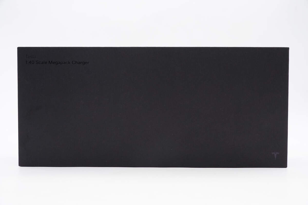
The packaging box is pure black, with the TESLA 1:40 Scale Megapack Charger printed in the upper left corner.

The Tesla logo is printed in the lower right corner.

The Tesla logo is printed in the center of the back, and specs info and a QR code are affixed to the lower left and right corners, respectively.

The box contains the power bank and some documents.

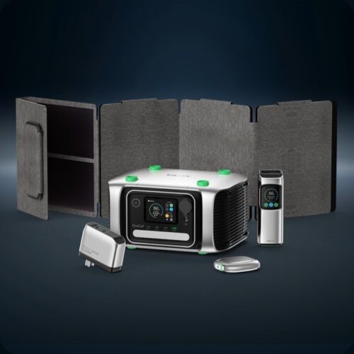
The power bank faithfully replicates the iconic design of the Megapack energy storage system at a 1:40 scale. It features a sharply defined rectangular silhouette with a matte metallic finish, capturing the industrial essence of its full-sized counterpart.

All service access panels are movable components, revealing intricately detailed replicas of internal battery packs and wiring once opened, showcasing impressive craftsmanship and attention to detail.
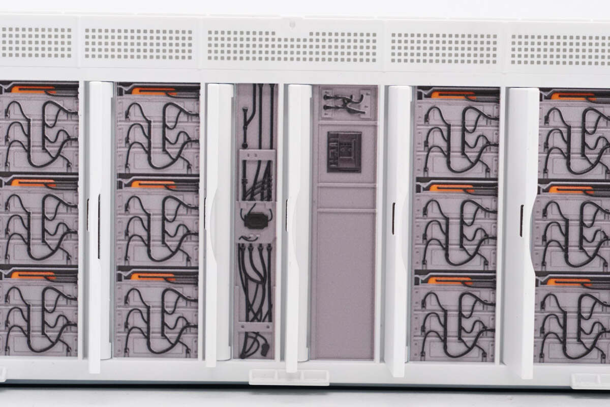
The interior details have also been reproduced.

A Tesla logo is embedded in the upper-right corner, which, when powered on, is illuminated by a red light.
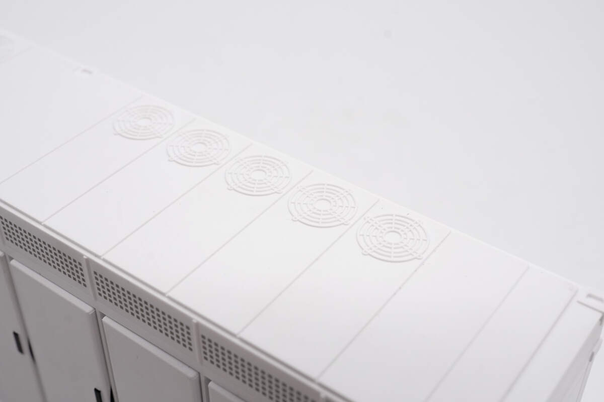
The multiple cooling fans on the top deeply restore the Megapack.

The plastic sheets of the two USB-C and one USB-A port are black.

The power button is on the top.

There are labels printed next to the three USB ports to help users distinguish them.

There are four battery indicator lights below, which light up blue, and each one represents 25% of the battery.

On the underside, a full-coverage rubber anti-slip pad ensures stability and is encircled by an LED light strip.

The specs info is also printed here.
Model is TSL03.
Battery Capacity: 3500mAh 21.9V/76.65Wh
Rated Capacity: 11000mAh(5V3A)
USB-C1 Input: 5V3A, 9V3A, 12V3A, 15V3A, 20V3.25A (Max 65W)
USB-C1/USB-C2 Output: 5V3A, 9V3A, 12VЗA, 15V3A, 20V5A (Max 100W)
USB-A Output: 5V3A, 9V2A, 12V1.5A

The length is about 22 cm (8.66 inches).

The height is about 71.74 mm (2.82 inches).

The width is about 46.2 mm (1.82 inches).

That's how big it is in the hand.

The weight is about 650.7 g (22.95 oz).

ChargerLAB POWER-Z KM003C shows that USB-C1 can support PD3.0, PPS, QC5, and DCP charging protocols.

And it has five fixed PDOs of 5V3A, 9V3A, 12V3A, 15V3A, and 20V5A. It has two sets of PPS, which are 3.3-11V/3A and 3.3-21V/3A.

ChargerLAB POWER-Z KM003C shows that USB-C2 can support FCP, SCP, AFC, QC3+/5, PD3.0, PPS, DCP, and Apple 2.4A charging protocols.

And it has five fixed PDOs of 5V3A, 9V3A, 12V3A, 15V3A, and 20V5A. It has two sets of PPS, which are 3.3-11V/3A, and 3.3-21V/3A.

Our tester shows the USB-A port can support FCP, AFC, QC3.0, DCP, and Apple 2.4A charging protocols.
Teardown
Next, let's take it apart to see its internal components and structure.

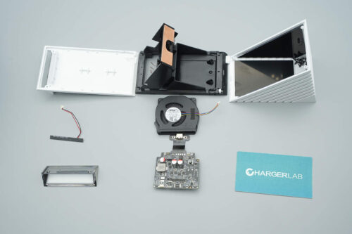
Remove the top cover, and the shell is fixed with buckles.

There is a small PCB on the top cover, with the logo indicator light and the power button on it.

Remove it, the power button is patch welded, and the LED indicator is covered with foam to prevent cross-lighting.

The battery pack is covered with a plastic shell for fixed protection, and screws are used to fix the two sides of the shell.

The thermistors at both ends of the battery pack are secured with tape.

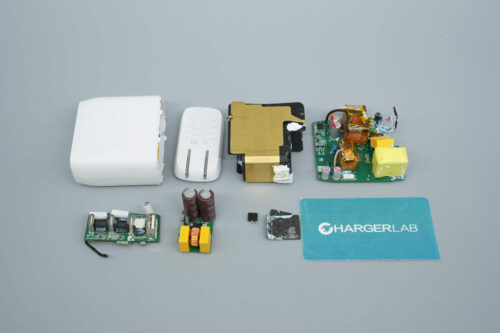
Remove the bottom shell and find the PCBA module inside.

The PCBA module is connected to the battery pack via red and black wires.

Remove the screws and take out the battery pack. The plastic shell is fixed with buckles.

Open the plastic protective shell, and you will see that the battery pack is wrapped in a blue cover.

Tear off the blue cover, the battery pack is composed of six 18650 lithium batteries, and the battery pack is also spot-welded to a PCB board via a nickel sheet.

There is barley paper pasted on both ends of the battery pack.

Take apart the battery pack.

The battery cells are all EVE INR18650/35V lithium-ion batteries with a battery capacity of 3500mAh, a nominal voltage of 3.65V, and a nominal energy of 12.78Wh, and have passed CE and CCC certification.

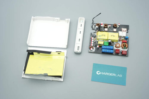
This is the PCB that connects to the battery pack.

The front of the PCBA module is covered with a metal heat sink, and multiple wires are connected to the edge.

There are several thermal pads under the heat sink corresponding to the heat-generating components.

There are also two black wires connected to the heat sink via screws.

The other end of the wire is connected to the PCBA module by soldering.

The soldering points between the two thermistors and the PCBA module are protected by glue.

Both ends of the two sets of wires used to connect the PCBA module to the other two PCBs are plug-in designs for easy assembly.

The front of the PCBA module has an MCU, lithium battery protection chip, lithium battery protection MOSFET, USB-C power management chip, buck-boost MOSFET, inductor, and other components, as well as multiple solid filter capacitors.

On the back, there is another voltage regulator controller for the USB-C port and a step-down SOC for the USB-A port.

The solid capacitor for input filtering is from NJcon. 35V 100μF.

The solid capacitor on the battery side is also from NJcon. 35V 100μF.

The lithium battery protection chip is from iCM. It supports the application of a 6-series battery pack and supports battery balancing. It has a built-in high-precision voltage detection circuit and current detection circuit, which can detect the voltage, current, and temperature of each battery in the series battery pack, and perform battery overcharge, over-discharge, charge overcurrent, discharge overcurrent, overheating, and battery pack disconnection protection functions. Model is CM1361.
It has a 15mV over-voltage detection accuracy and, through an external sampling resistor, can achieve high-precision battery current detection. It supports three-stage discharge overcurrent protection and charging overcurrent protection. The addition of balancing functionality ensures that each cell in the battery pack is fully charged, maximizing battery performance. The chip supports the connection of a thermistor for battery pack temperature protection and offers customizable functions to meet the protection needs of multi-series lithium battery packs.

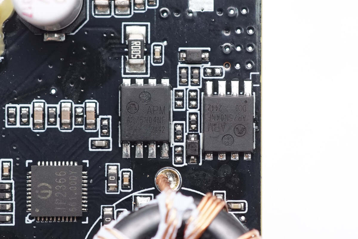
The two lithium battery MOSFETs are from APM and adopt the PDFN5*6-8L package. Withstand voltage 40V, resistance 4.5mΩ. Model is AP75N04NF.

The power management chip for USB-C is from INJOINIC. It supports multiple protocols, such as PD3.1, and the charging and discharging power is up to 140W. It has high integration and rich functions, only one inductor is needed to realize synchronous buck-boost function, and only a few peripheral devices are needed in the application, which effectively reduces the size of the overall solution and reduces BOM cost. Model is IP2366.

The IP2366 supports 2 to 6 series-connected battery cells and allows users to configure the number of series cells and battery type via external resistors. The fully charged voltage options include 3.65V, 4.1V, 4.2V, 4.35V, and 4.4V. It features built-in control loops for chip temperature, battery temperature, and input voltage detection, and can intelligently adjust the charging current based on the detected charger power.
The IP2366 also supports a low-power mode, reducing standby current to just 5μA. When a charger is connected, the chip automatically wakes up and begins charging; to discharge externally, a short press of a button is required to wake it. The chip includes a built-in 14-bit ADC, enabling precise measurement of input voltage and current, as well as battery voltage and current. Charging and discharging voltage, charging current, and other data can be accessed via the I2C interface.
The IP2366 comes in a 5x5 mm, 0.4mm pitch QFN40 package and provides multiple protection features, including input over-voltage and under-voltage protection, output overcurrent and short-circuit protection, battery overcharge, over-discharge, overcurrent protection, chip over-temperature protection, and NTC-based battery temperature protection. Both CC1 and CC2 pins support 30V voltage tolerance, offering robust protection against damage and ensuring high reliability.

The four synchronous buck-boost MOSFETs are from APM. Model is AP75N04NF.
The other two synchronous buck-boost MOSFETs are of the same model.

There is a buck-boost inductor.

There is a solid capacitor. 35V 220μF.

The other solid capacitor has the same specifications.

Another USB-C power management chip is also from INJOINIC. Model is IP2366.

The four synchronous buck-boost MOSFETs are also from APM. Model is AP75N04NF.

There are two other synchronous buck-boost MOSFETs here.

There is a buck-boost inductor.

Here is the solid capacitor. 35V 220μF.

The other solid capacitor has the same specifications.

The SMD common mode choke equipped for the two USB-C ports is used to filter high-frequency interference.

The buck protocol chip for the USB-A port is from INJOINIC. It supports four types of fast charging protocols and features a built-in power MOSFET, with a step-down conversion efficiency of up to 98%. The input voltage range is from 9.6V to 32V, and the output voltage range is from 3V to 12V, with a maximum output power of 18W. Additionally, it can automatically adjust the output voltage and current based on the detected fast charging protocol. Typical output voltage and current options include 5V/3.4A, 9V/2.0A, and 12V/1.5A, providing a complete solution for car chargers, fast charging adapters, and power strips. Model is IP6525T.

Here is the information about INJOINIC IP6525T.

Here is the buck inductor.

This is the solid capacitor for output filtering for the USB-A port. 16V 100μF.

This is the MCU, the information is unknown.

The non-synchronous step-down DC-DC converter for powering the MCU and LED lamps is from MD. It integrates MOSFET, supports 20V input voltage and 0.6A output current, and adopts the SOT23-6L package. Model is MD8941.

This is the buck inductor. 6.8μH.

This is the filter capacitor. 16V 220μF.

There are the LED indicator lights.

This is the thermistor.

Well, those are all components of the TESLA 1:40 Scale Megapack Charger.
Summary of ChargerLAB

Here is the component list of the TESLA 1:40 Scale Megapack Charger for your convenience.
The TESLA 1:40 Scale Megapack Charger is a power bank that perfectly replicates the industrial design style of the Megapack energy storage system. With its highly recognizable appearance, it exudes a strong sense of technology and carries significant collectible value, making it a must-have for Tesla enthusiasts and tech fans alike.
It comes equipped with two USB-C ports and one USB-A port, offering a total of three interfaces. The USB-C ports support 65W input and up to 100W output, while the USB-A port supports 18W output. Additionally, it features a 21,000mAh battery, which provides excellent performance and battery life by today’s standards. This allows it to efficiently charge multiple devices simultaneously, meeting users' needs for fast charging and multi-device power delivery.
After taking it apart, we found that it has 6 EVE INR18650/35V lithium-ion batteries, and uses iCM's CM136 lithium battery protection chip that supports battery balancing function to ensure the safety and life of the battery pack. At the same time, it is equipped with a combination of two INJOINIC IP2366 power management chips and an IP6525T step-down SOC, which realizes efficient charge and discharge management and multiple protection functions of the USB interface, further improving the reliability and user experience of the product. The battery pack is completely isolated from the PCBA module. The PCBA module is equipped with thermal pads and heat sinks, and the connecting wires are glued for enhanced protection. The overall workmanship is exquisite.
Related Articles:
1. Unboxing of Tesla 1:40 Scale Megapack Charger
2. Review of TESLA 1:40 Scale Megapack Charger
3. iCM Chip Joins Tesla Supply Chain: A Milestone for China’s Semiconductor Industry