Introduction
As a new power solution for electric vehicles, battery swapping offers a fast, safe, and convenient alternative to traditional charging. When the battery runs low, users can simply visit a swap station and replace it with a fully charged pack. These battery packs are produced by trusted manufacturers, feature comprehensive protection systems, and are charged centrally at swap stations for improved safety.
In this teardown, we take a look at the Zhiba MAX swappable battery pack from Zhizu. It features a stainless steel casing and a 20-series LiFePO₄ cell configuration with a rated capacity of 45Ah. The pack includes a built-in GPS anti-theft system and a proprietary connector to prevent unauthorized charging. Let’s dive into its internal design and components.
Product Appearance
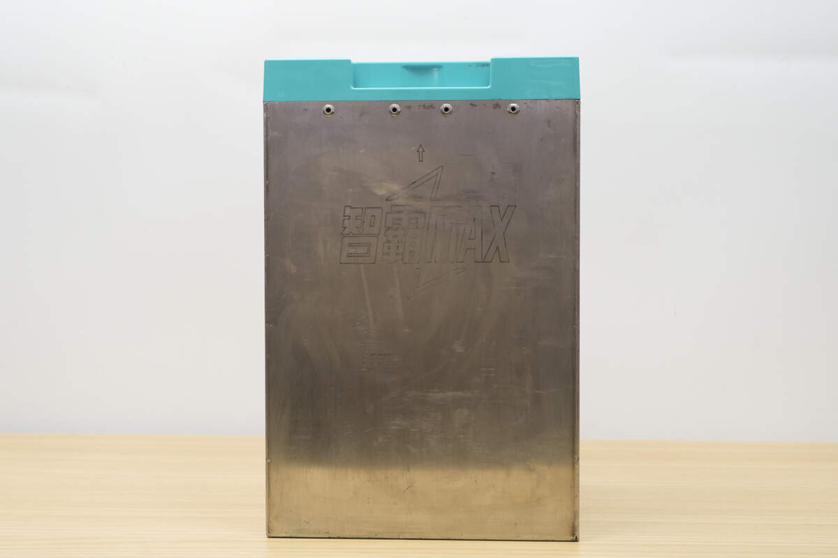
The battery pack uses a stainless steel enclosure.
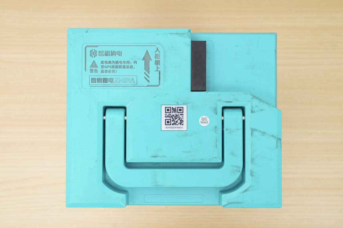
The top features a blue plastic cover with a built-in handle.
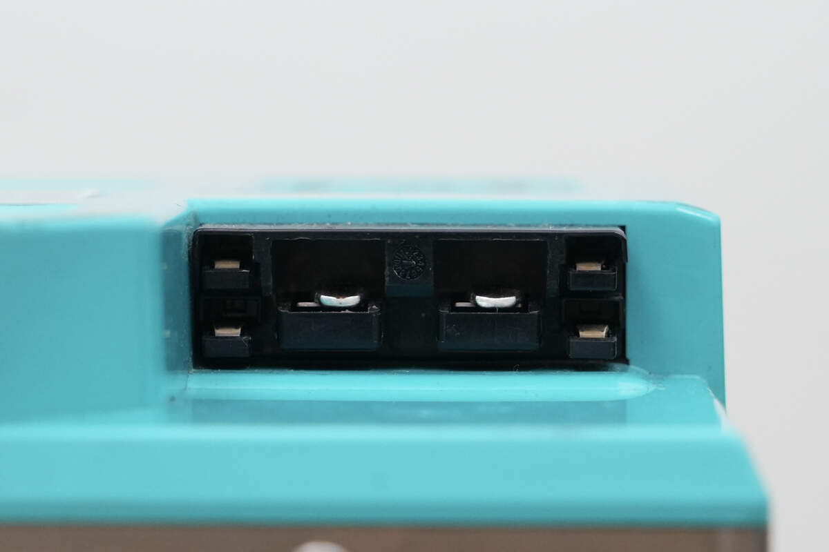
The connector includes a physical anti-misplug design.
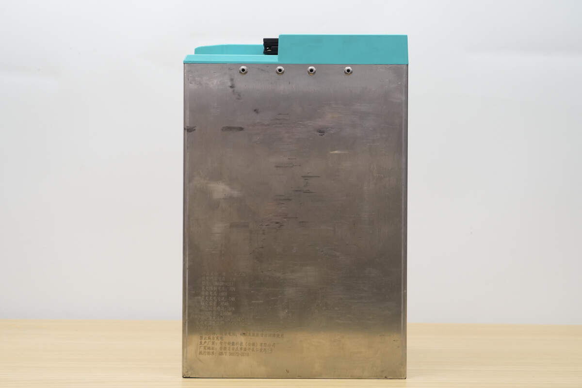
Product information is printed on the side.

Product Name: Lithium-ion Battery Pack
Discharge Cut-off Voltage: 56V
Model: DM60N-45ET
Charge Limit Voltage: 70V
Nominal Voltage: 60V
Maximum Charging Current: 14A
Rated Capacity: 45Ah
Maximum Discharge Current: 60A
Rated Energy: 2700Wh
Charging Temperature Range: 0℃ to 50℃
Discharging Temperature Range: -20℃ to 60℃
Service Life Under Normal Conditions: 5 Years
Do not disassemble or modify the battery.
Do not use if damaged or swollen.
Unauthorized charging is prohibited.
Manufacturer: Zhixing Xinneng Technology (Anhui) Co., Ltd.
Standard: GB/T 36672-2018

The bottom is secured by welding.
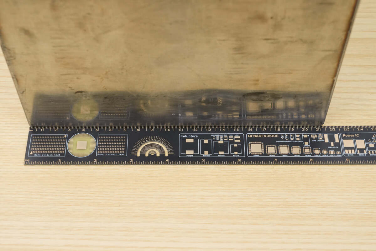
The width is about 215 mm (8.46 inches).
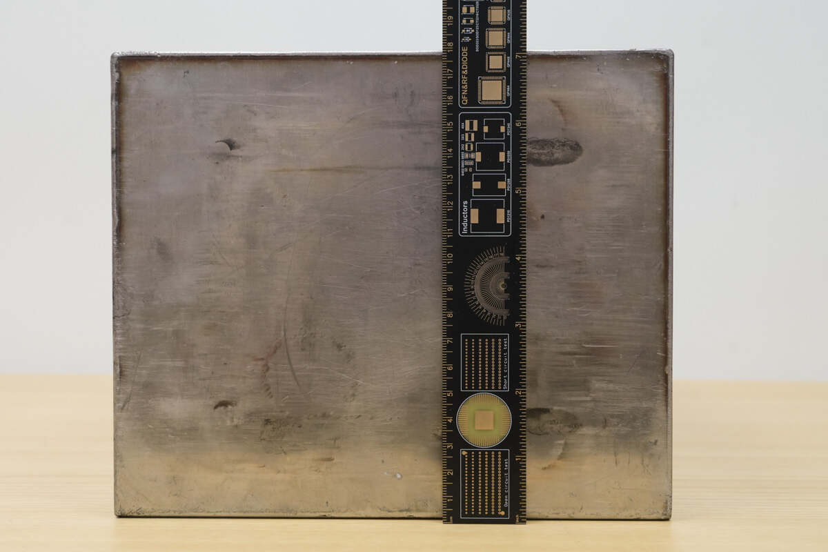
The height is about 180 mm (7.087 inches).

The length is about 327 mm (12.87 inches).
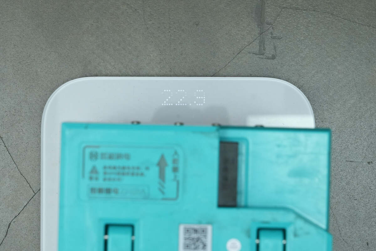
The weight is about 22.5 kg.
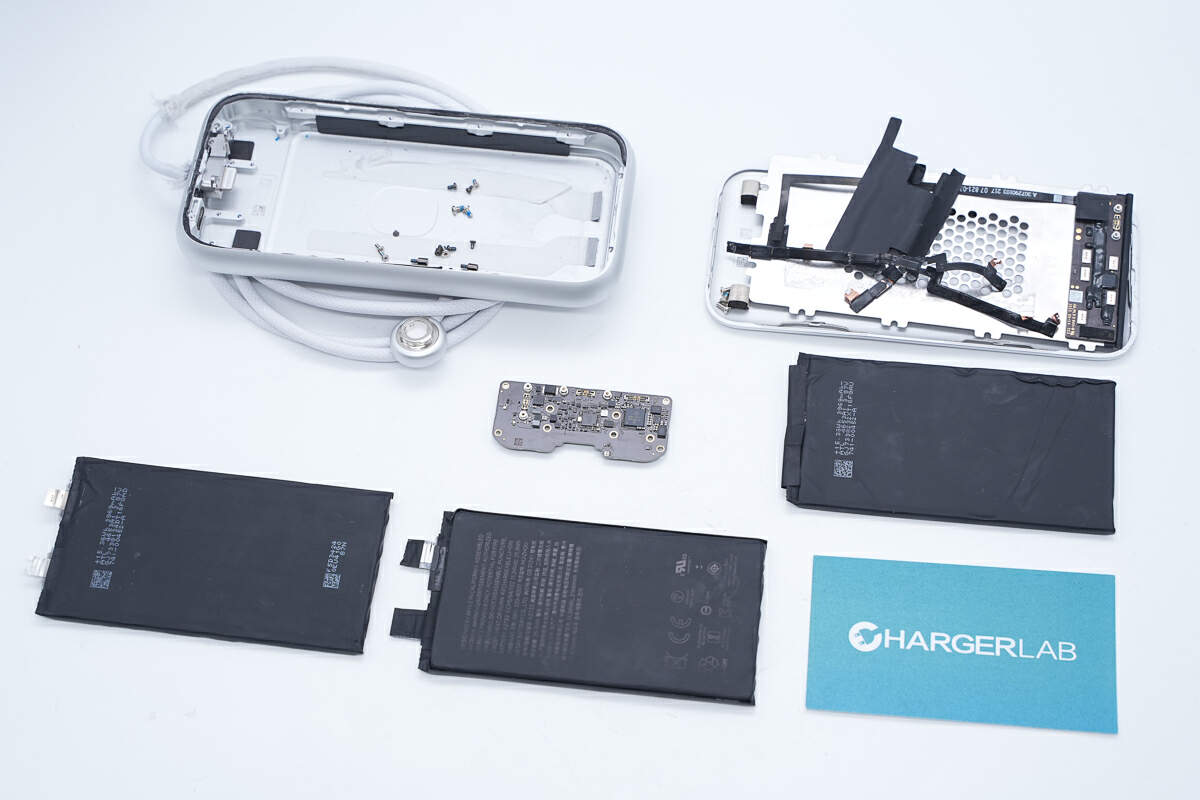
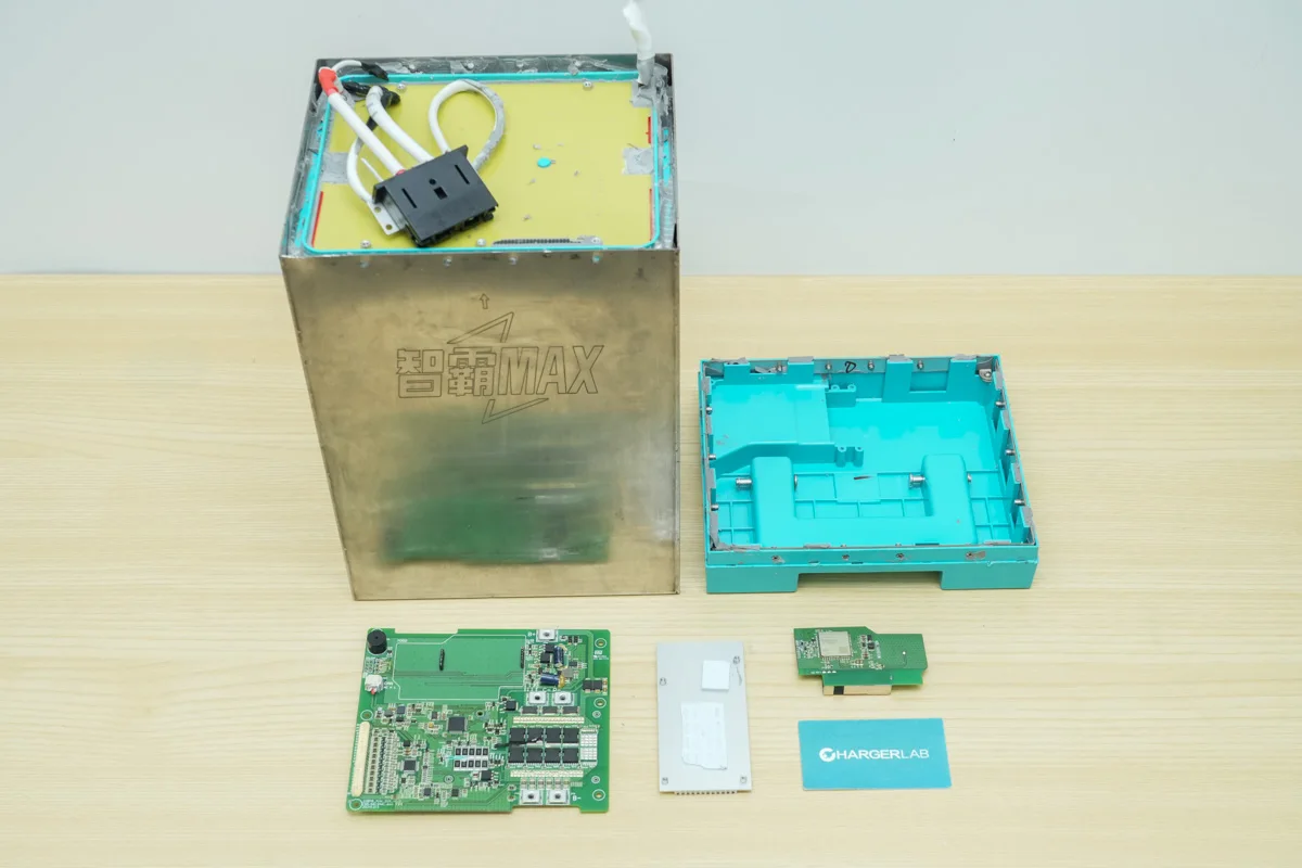
Teardown
Next, let's take it apart to see its internal components and structure.
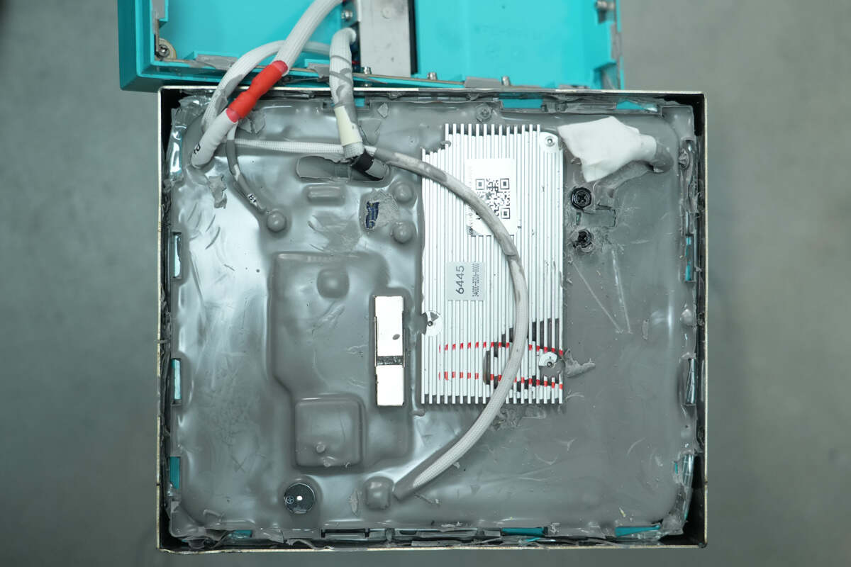
Remove the rivets and open the top cover, the protection PCB is covered with adhesive.
Disconnect the battery pack's negative terminal from the protection PCB.
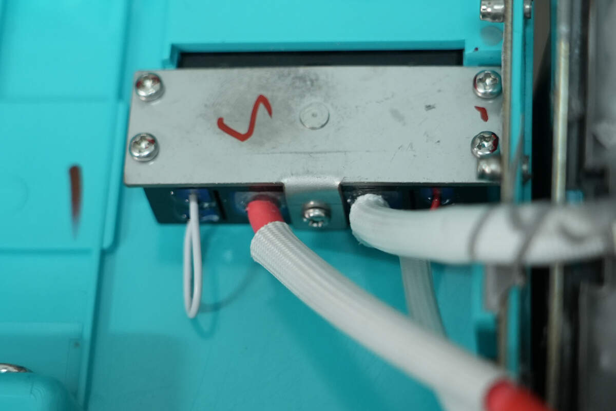
The output connector is secured to the enclosure with screws and a clamping plate.
Remove the adhesive. The PCBA module is secured to the phenolic board with screws.
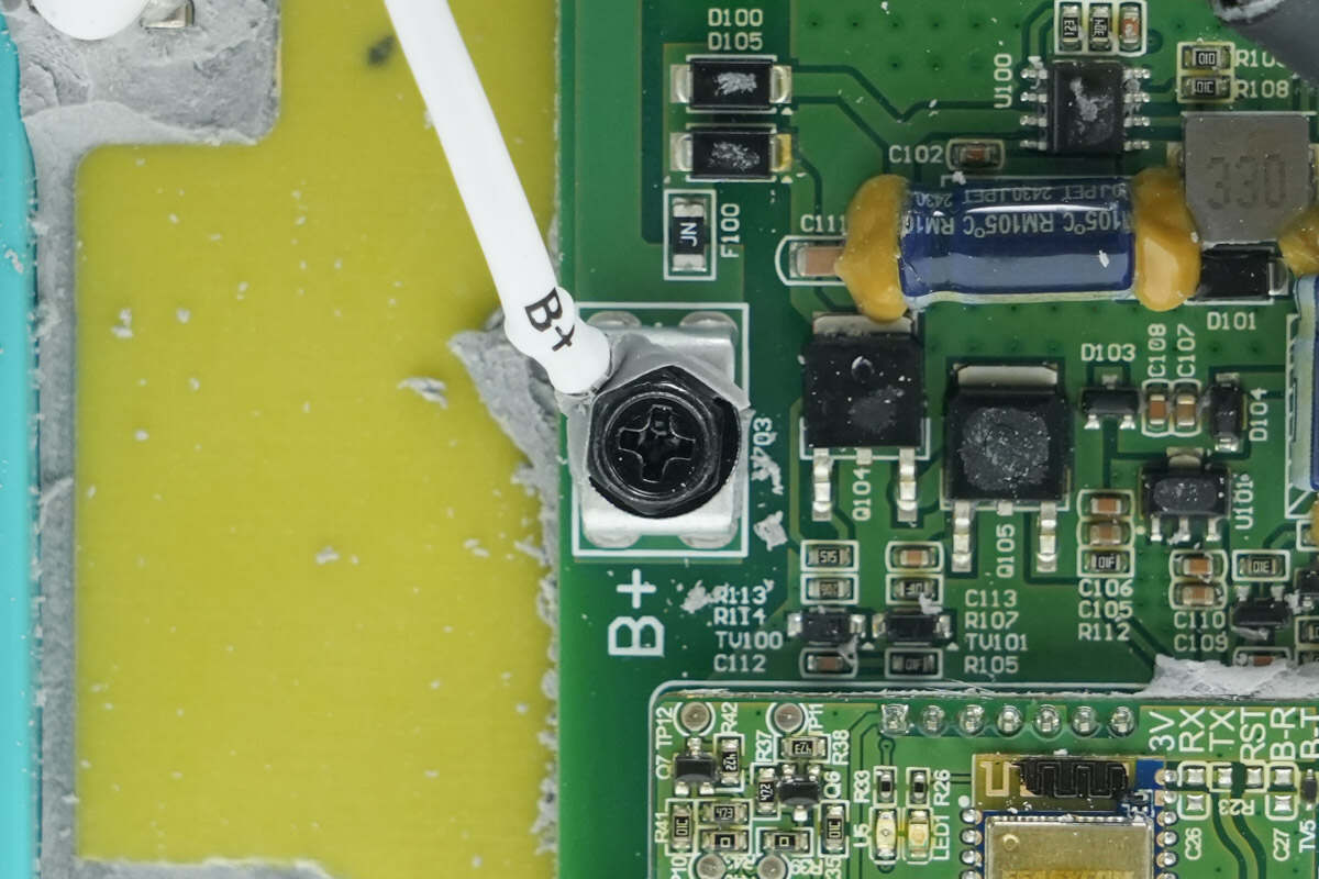
The battery pack's positive terminal is connected to the protection PCB via a screw terminal.
The negative terminal is also connected via a screw terminal.
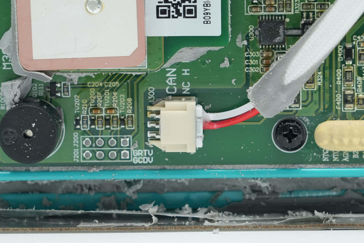
The CAN communication interface uses a plug connector.

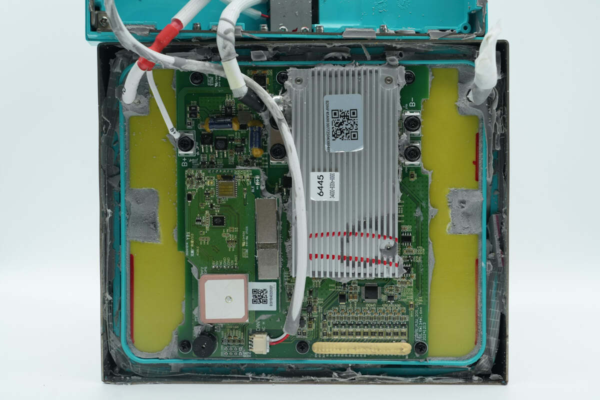
The plastic frame and phenolic board below the protection PCB are sealed with adhesive.
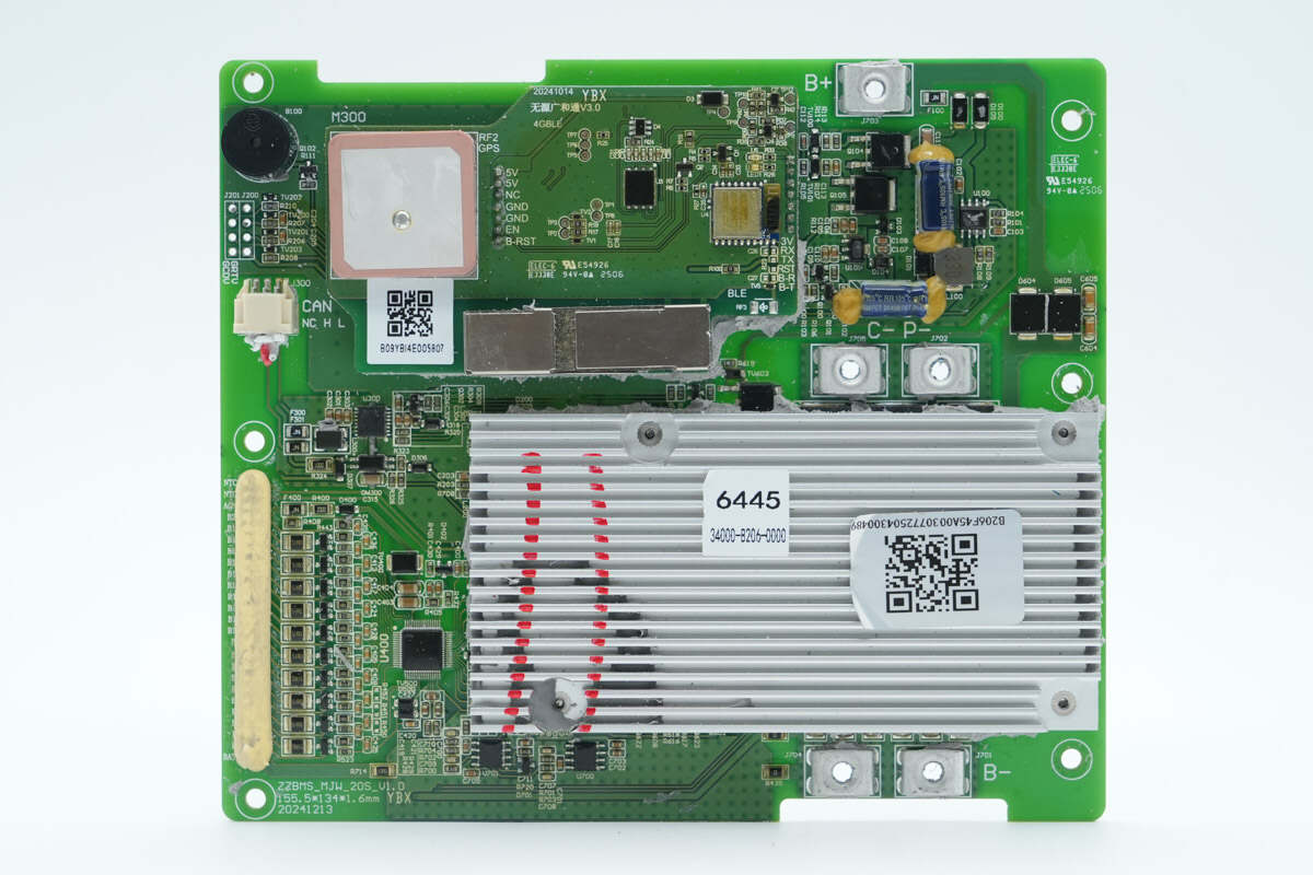
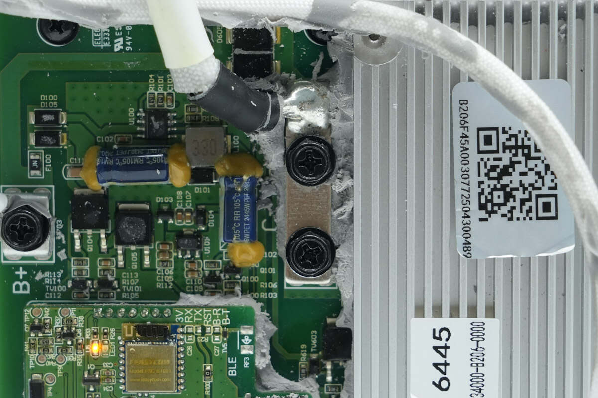
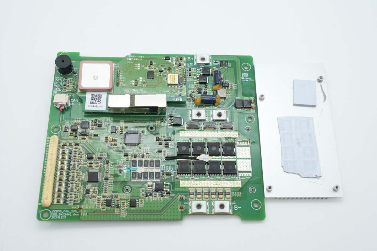
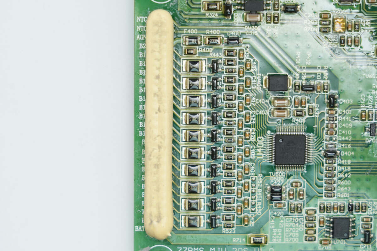
On the left side of the PCB are the GPS positioning, 4G, and Bluetooth communication modules, along with the battery cell voltage connector. On the right side are the buck converter circuit, heat sink, and negative terminal screw.
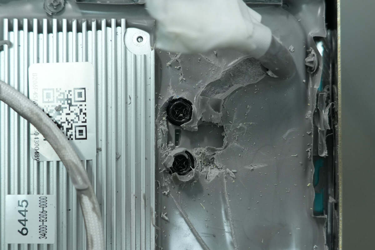
The heat sink is secured with screws and has thermal pads on the back.
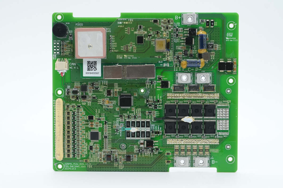
Below the heat sink are the battery protection MOSFETs and pre-discharge resistors.
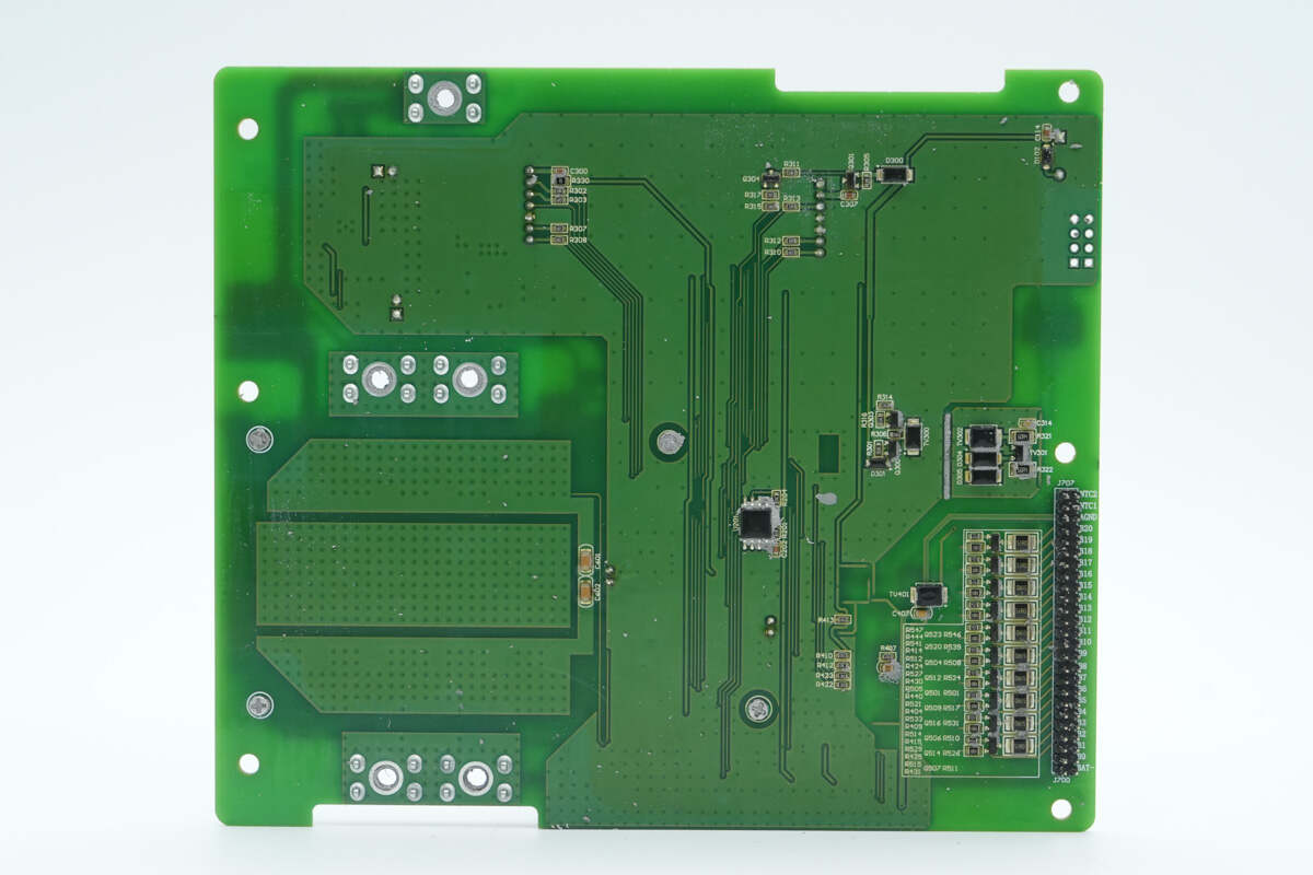
On the back are the memory chip and the connector for monitoring individual battery cell voltages.
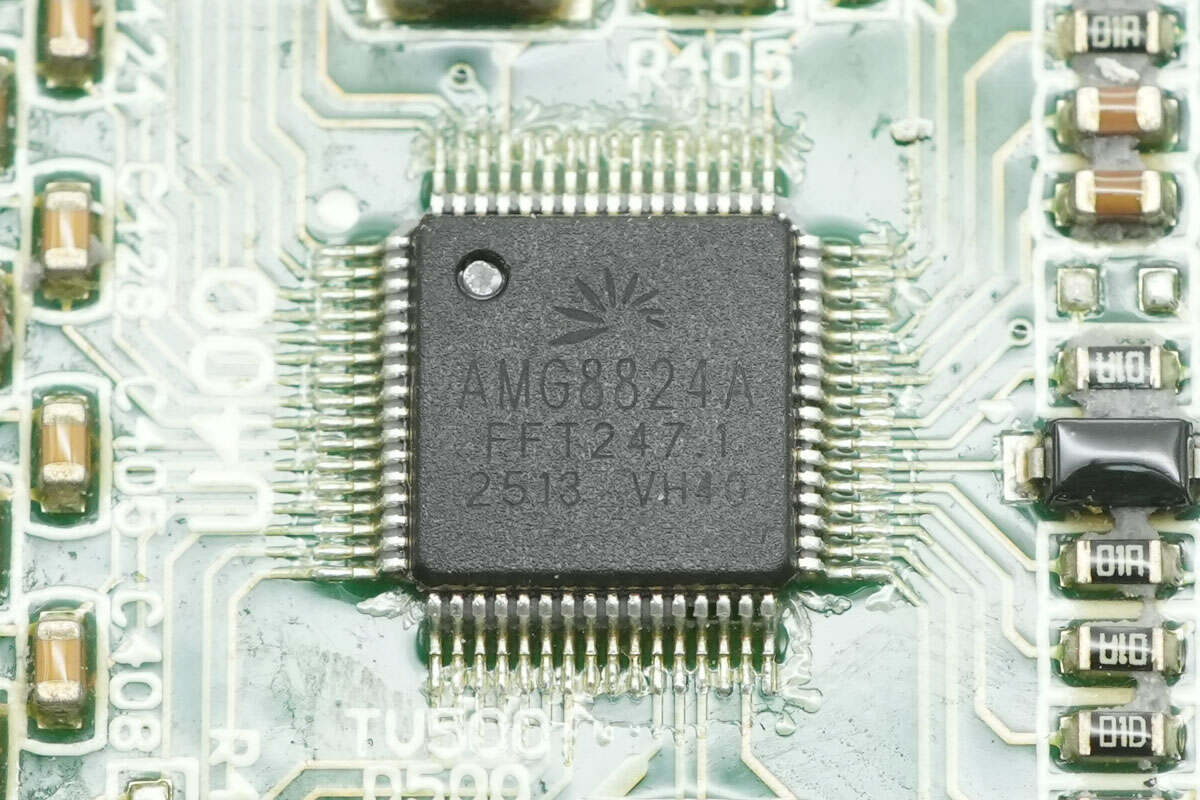
The battery protection chip is from Amagictech, model AMG8824A. It is a high-reliability, high-performance lithium battery management SoC supporting 3 to 24 series cells. Based on the MagicBMS system architecture, it integrates high-precision signal acquisition and conversion, a full-function protection hardware state machine, and a high-voltage switching buck converter. It can provide battery protection and monitoring without requiring an external MCU or buck converter.
It can work with an MCU for monitoring, enabling software protection, and state-of-charge calculation to enhance system redundancy and protection reliability. The chip integrates high-precision battery protection features, including over-voltage and under-voltage protection, charge and discharge temperature protection (high and low), charge and discharge over-current protection, and discharge short-circuit protection. It also supports cell voltage balancing, battery connection open-circuit protection, and electronic lock control.
The AMG8824A integrates an ADC supporting individual cell voltage monitoring, battery charge and discharge current monitoring, and pack voltage monitoring. It also includes a high-precision ADC for current sensing and coulomb counting. The chip features a high-voltage switching buck circuit, integrated low-side NMOS driver, supports normal operation and sleep modes, and comes in an LQFP-64L package.
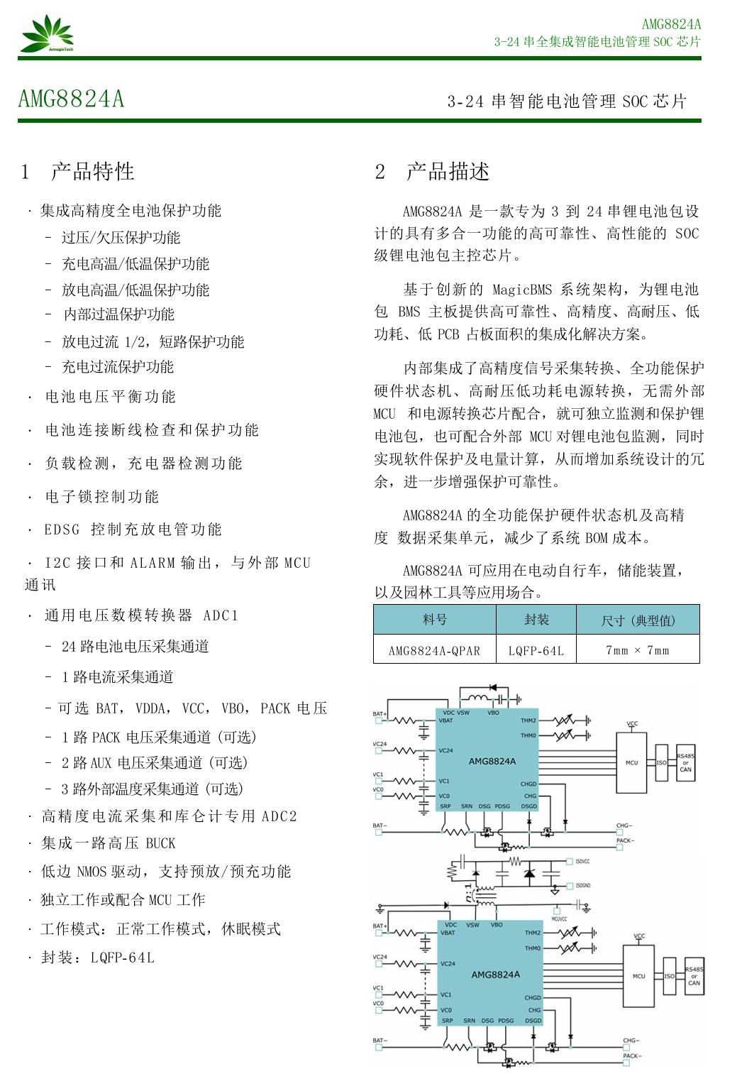
Here is the information about Amagictech AMG8824A.
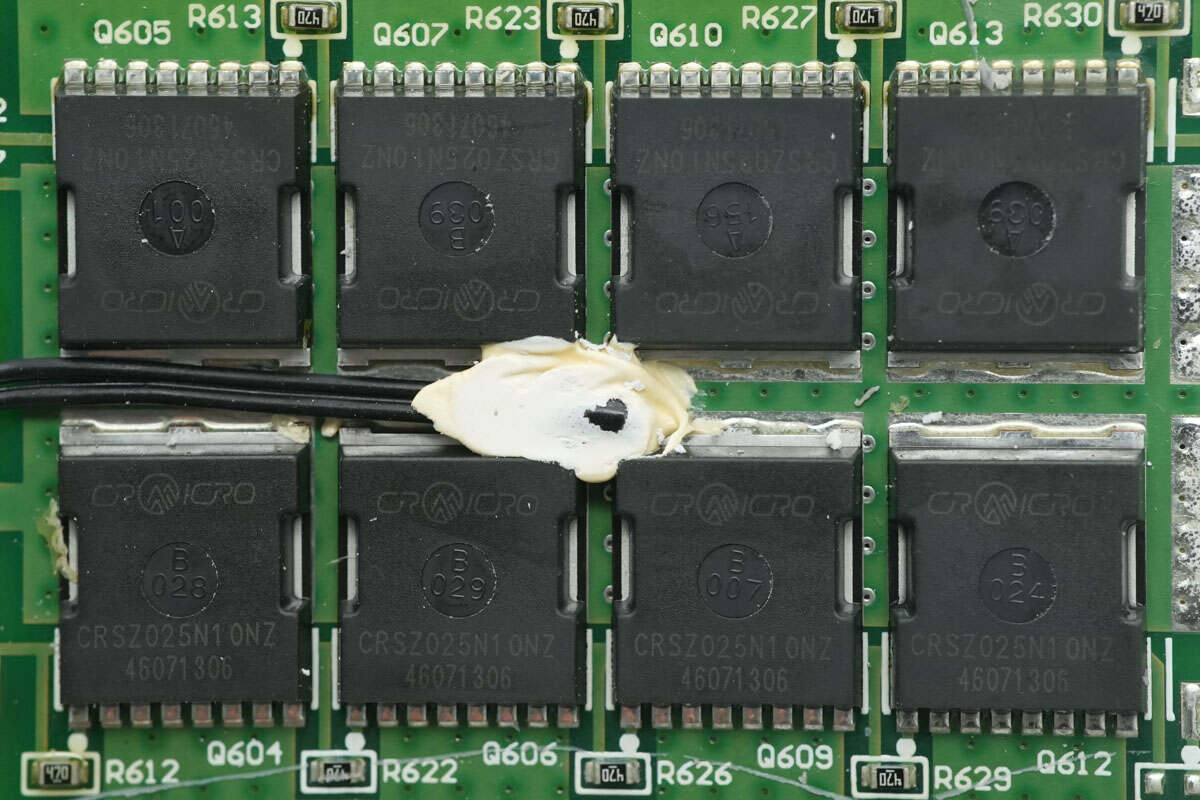
The battery protection MOSFETs are from CR MICRO, model CRSZ025N10NZ. These are NMOS devices rated for 100V, with an on-resistance of 2 mΩ, and come in a TOLL package.
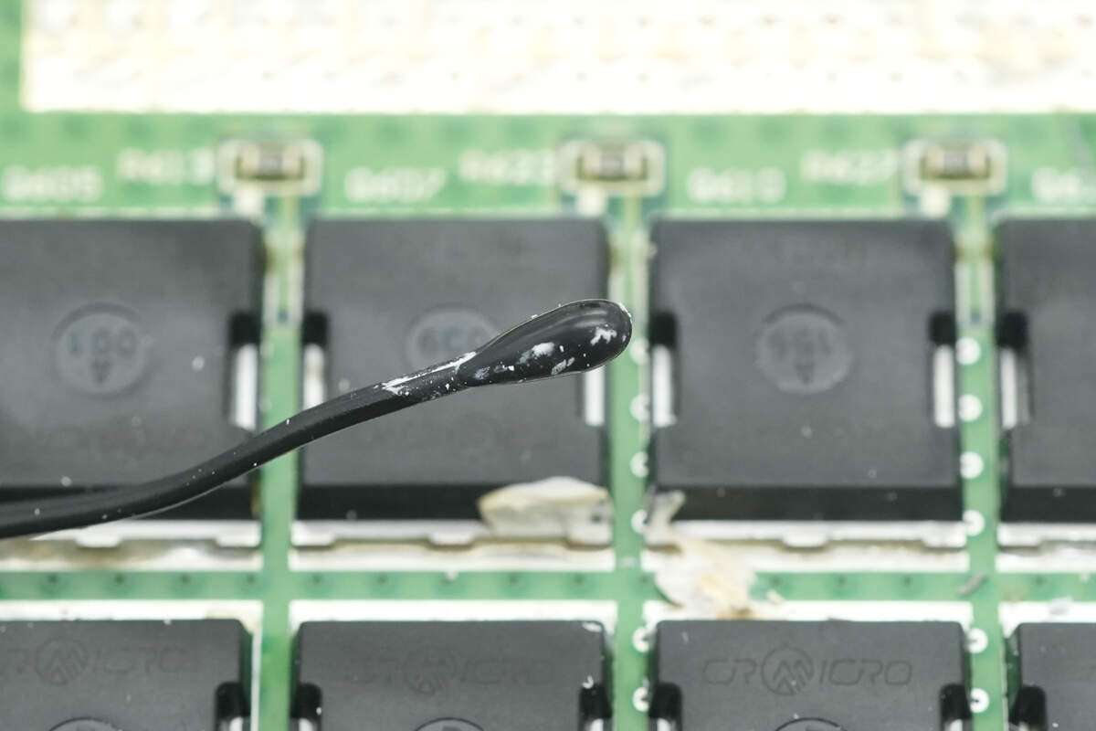
Close-up of the thermistor used to monitor the temperature of the battery protection MOSFETs.
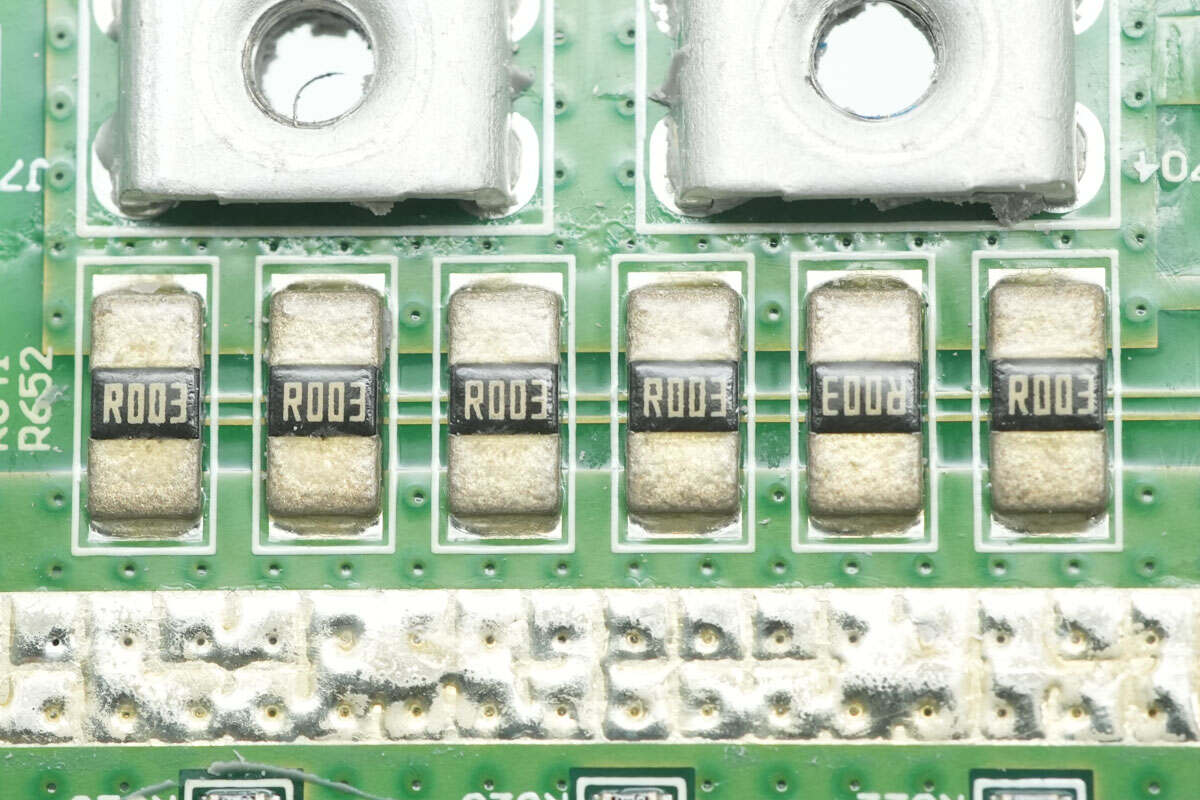
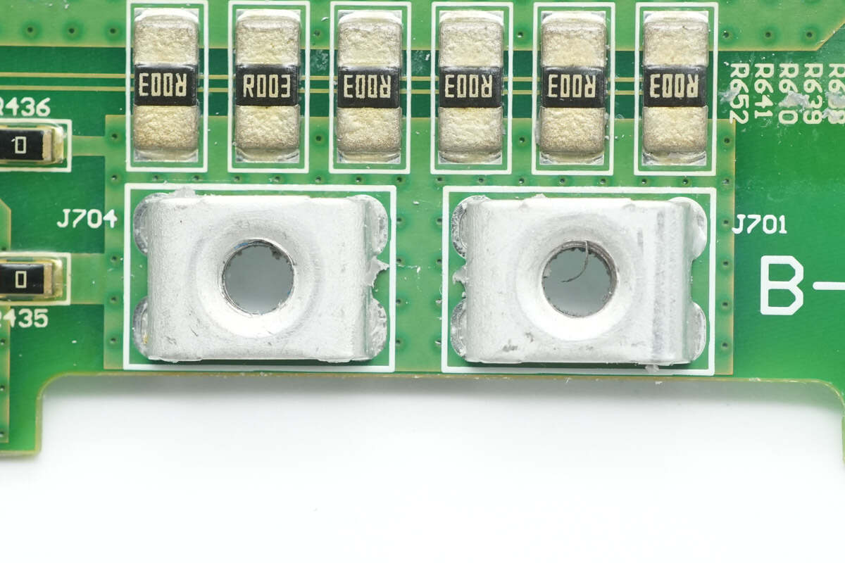
Six 3 mΩ sense resistors are connected in parallel to measure charge and discharge current.
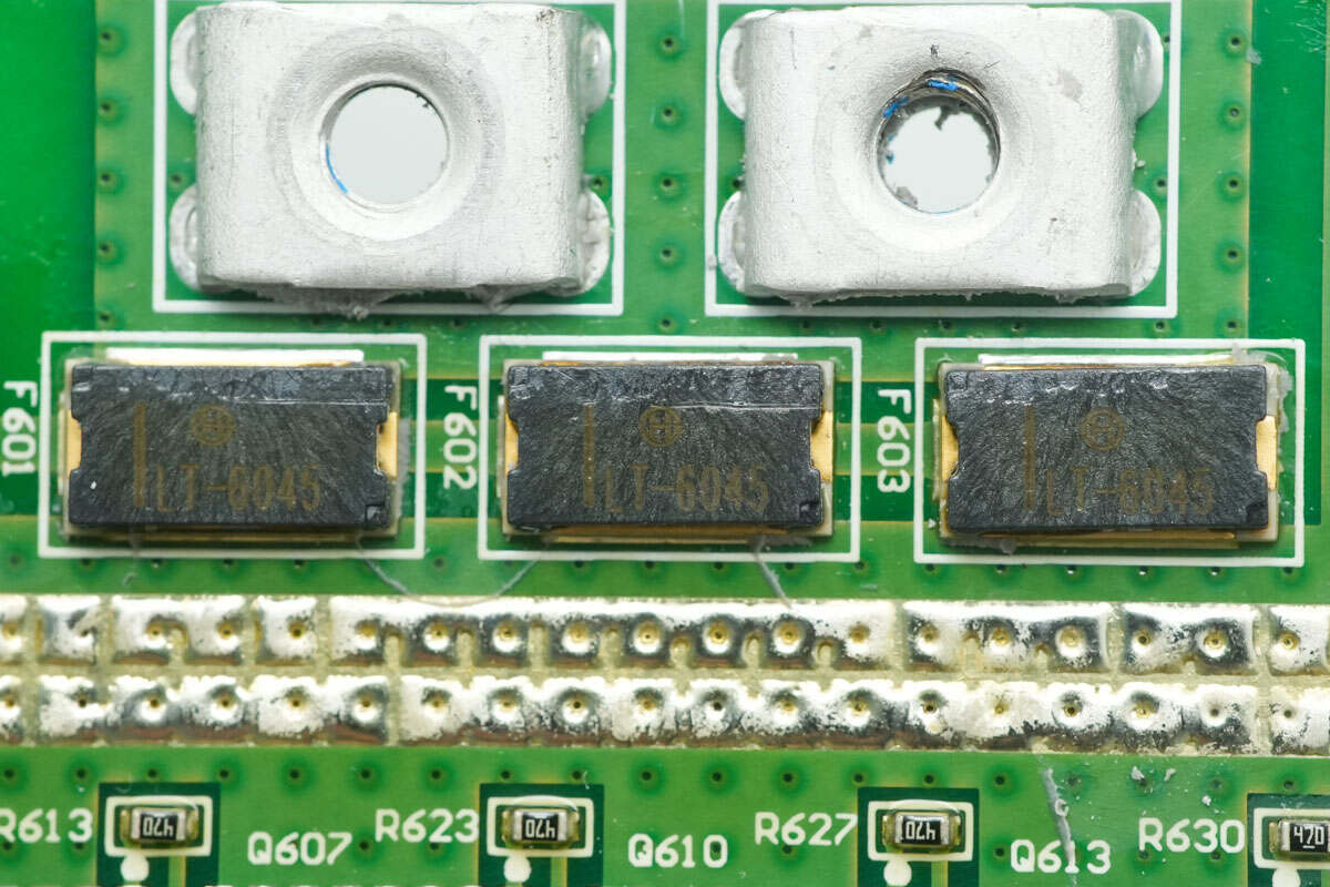
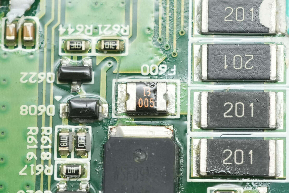
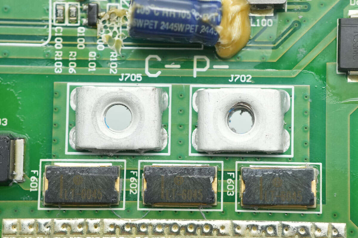
The three-terminal fuse is from Hollyfuse, model LT-6045. It is rated for 45A and 80V, with a breaking capacity of 120A. It supports applications with up to 20 series-connected cells and is certified by UR and TUV.
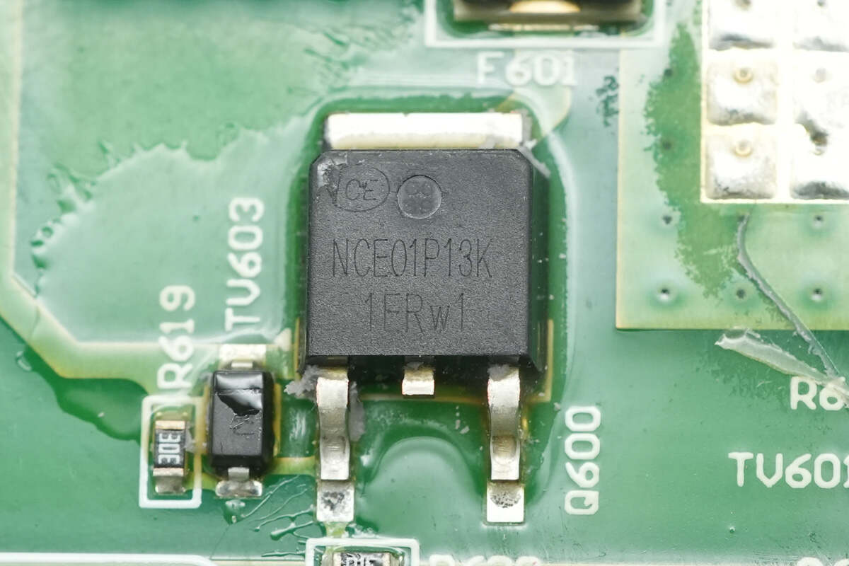
The fuse control MOSFET is from NCE, model NCE01P13K. It is a PMOS transistor rated for -100V with an on-resistance of 170 mΩ, and comes in a TO-252-2L package.
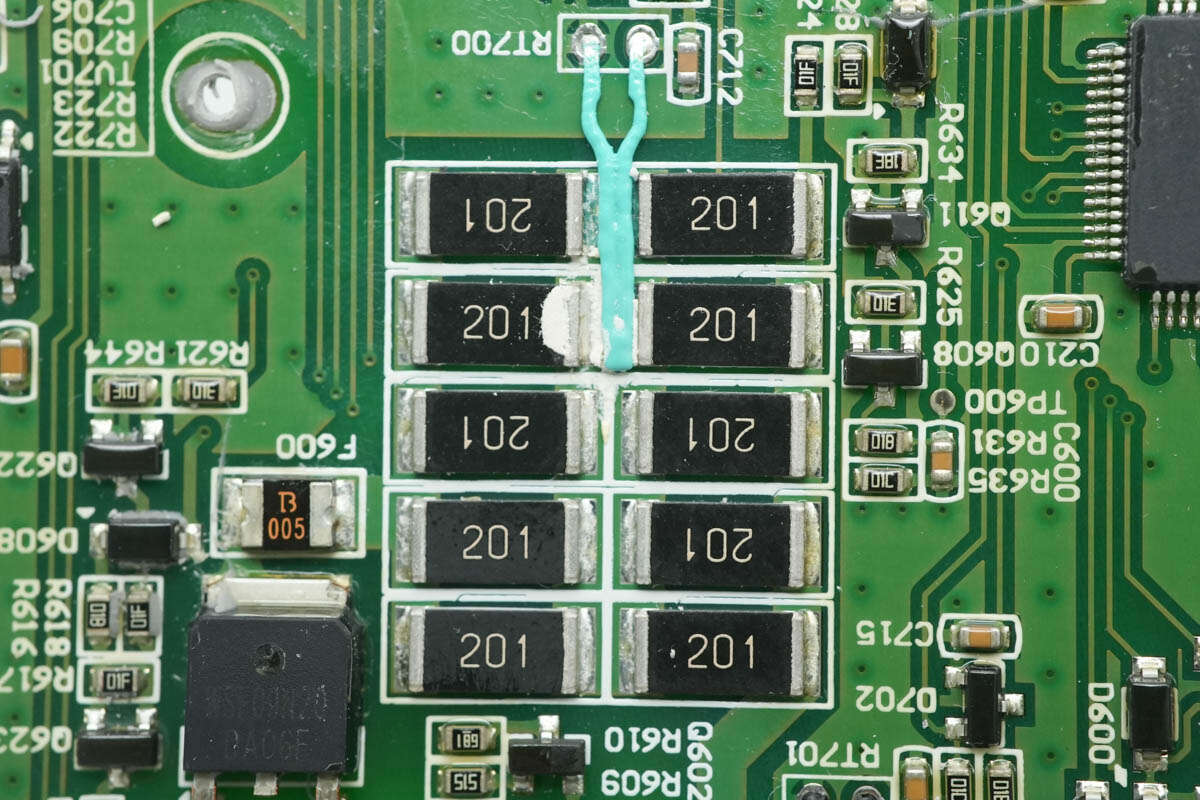
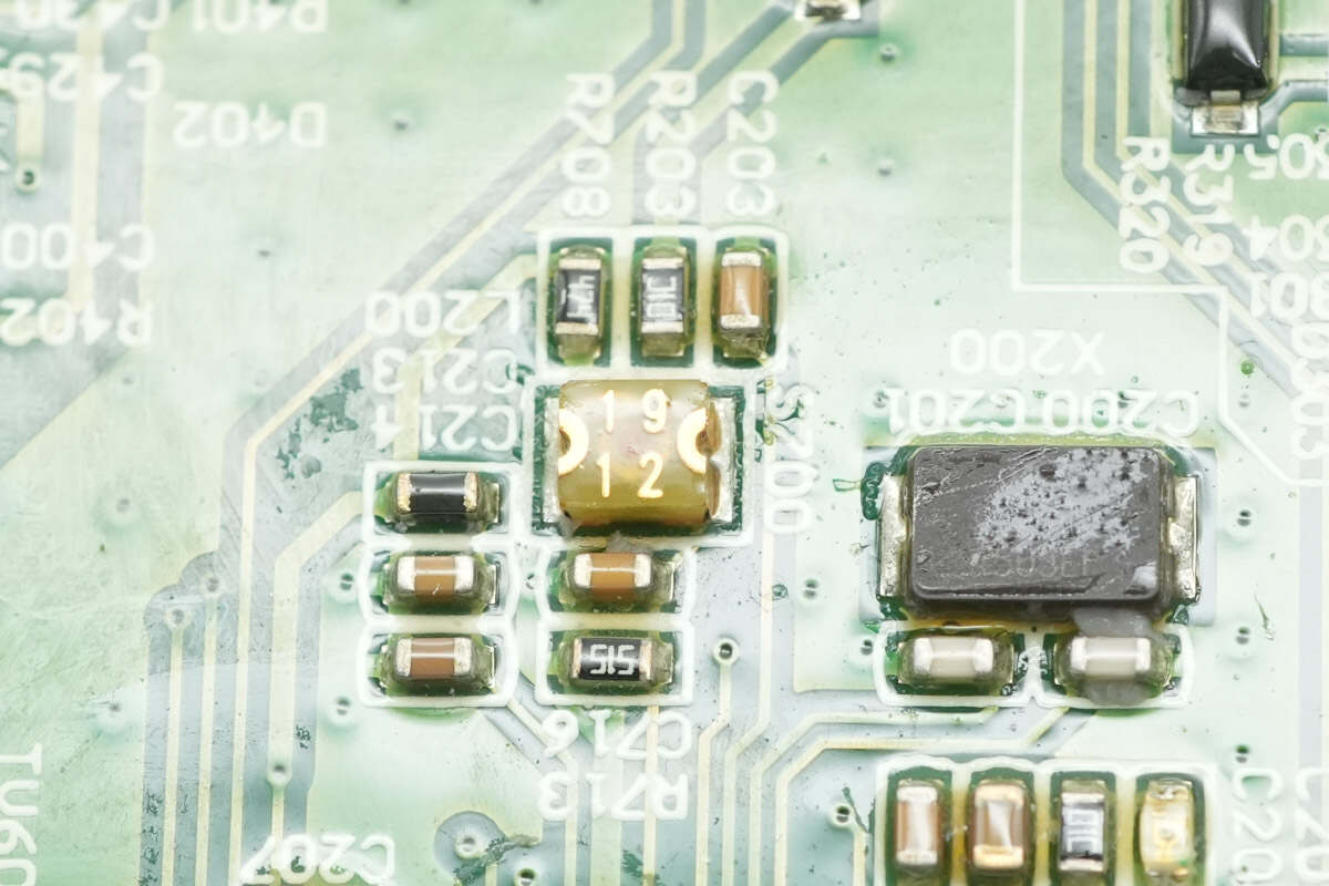
The pre-discharge current-limiting resistor network consists of ten 200 Ω SMD resistors arranged in a 5-parallel, 2-series configuration, resulting in an equivalent resistance of 80 Ω.
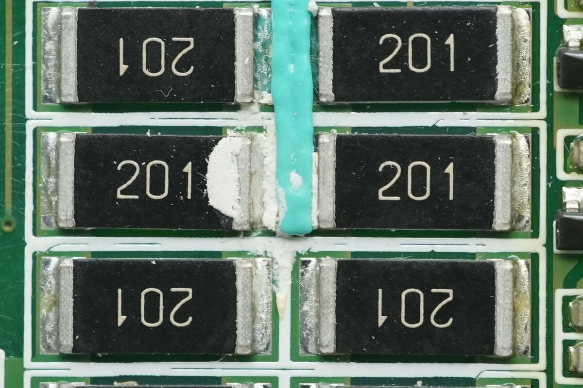
A thermistor is placed in the middle of the resistors.
The current-limiting resistor is connected in series with a resettable fuse.
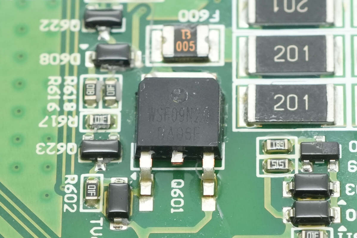
The pre-discharge MOSFET is from WINSOK, model WSF09N20. It is an NMOS transistor rated for 200 V with an on-resistance of 210 mΩ and comes in a TO-252 package.
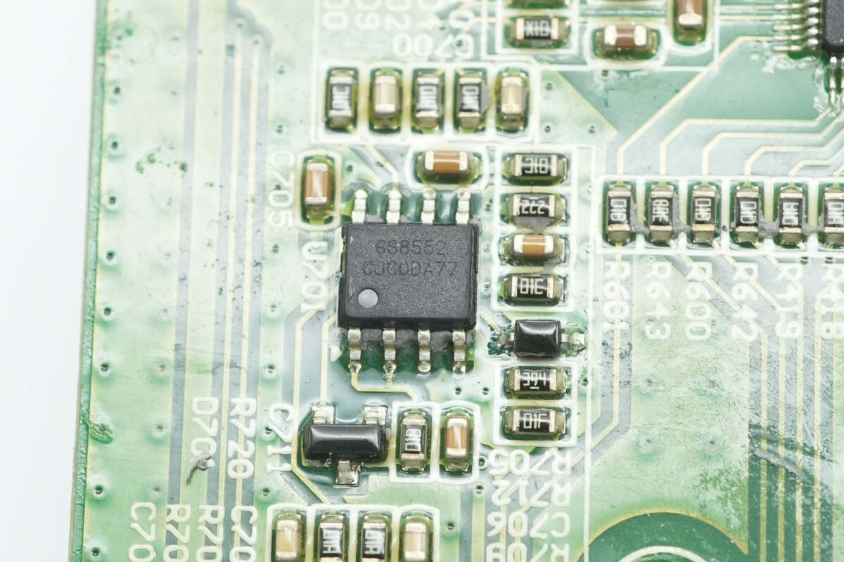
The op-amp is from Gainsil, model GS8552. It is a zero-offset, rail-to-rail dual operational amplifier that supports a single supply voltage from 1.8 V to 5.5 V and comes in an SOP-8 package.
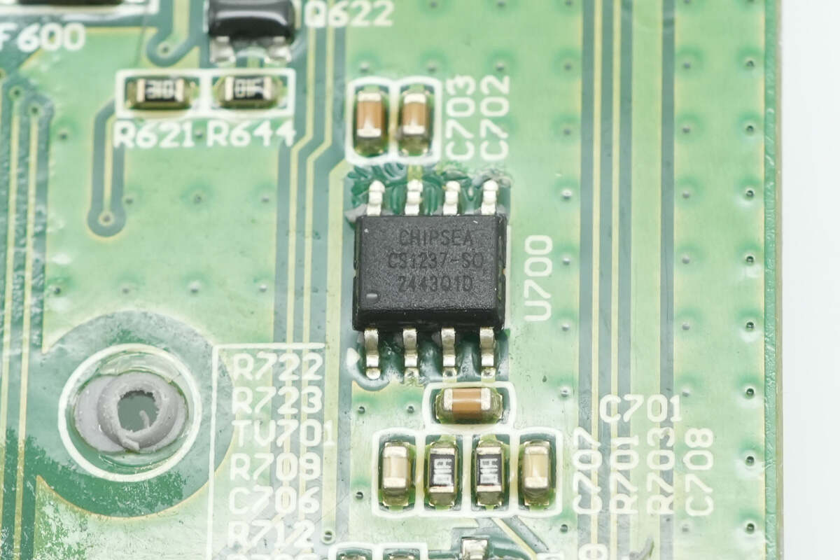
The analog-to-digital converter is from Chipsea, model CS1237. It is a high-precision, low-power ADC featuring a built-in differential input channel, integrated temperature sensor, and high-accuracy oscillator. It includes a 24-bit ADC with a programmable gain amplifier and communicates via an SPI interface. Packaged in an SOP-8, it works together with the op-amp for battery pack current sensing.
Balancing resistors and balancing MOSFETs are placed on both sides of the PCB.
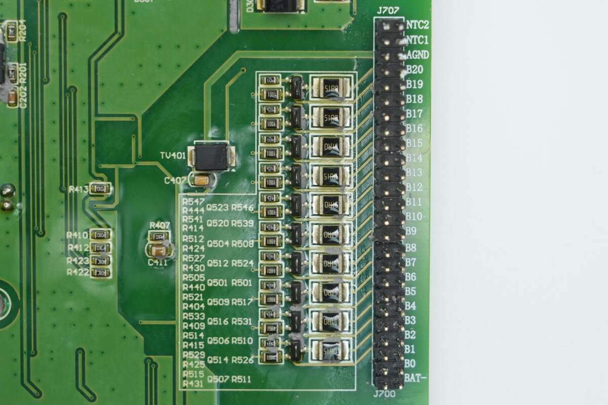
Close-up of the balancing MOSFETs and resistors on the back.
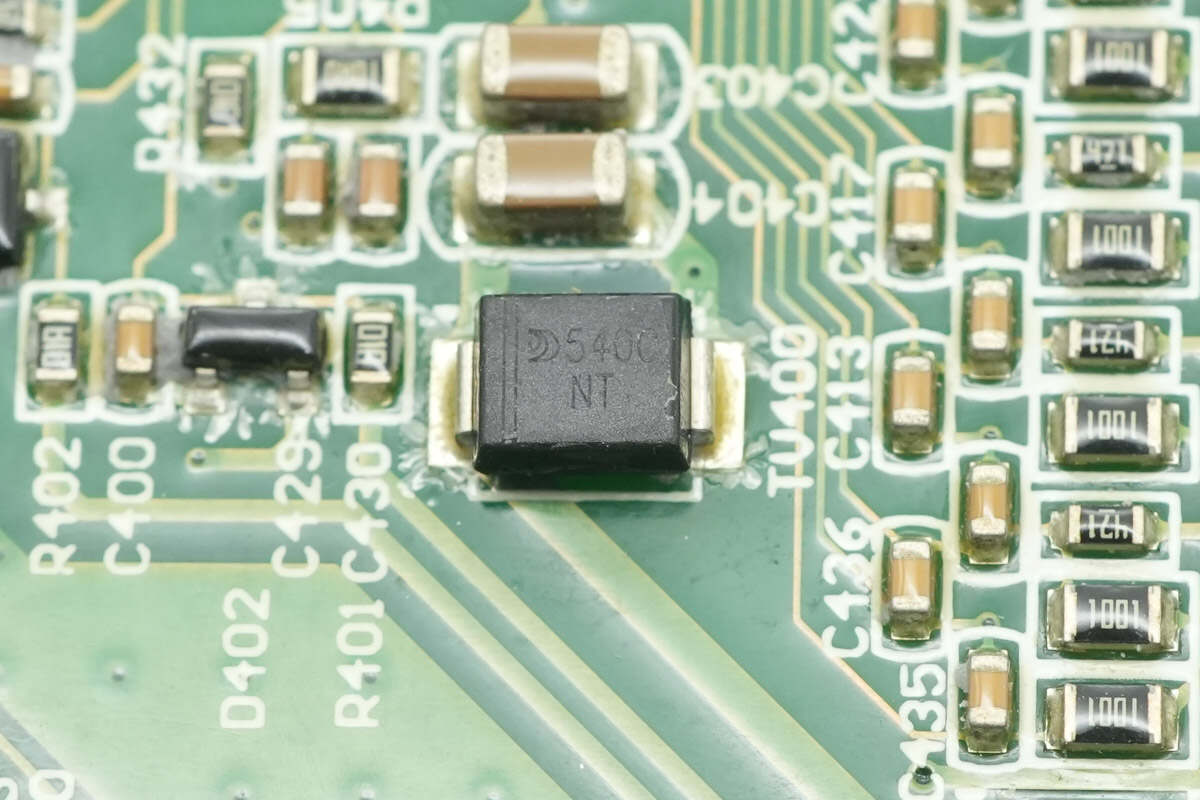
The TVS diode used for overvoltage protection is marked with "540C."
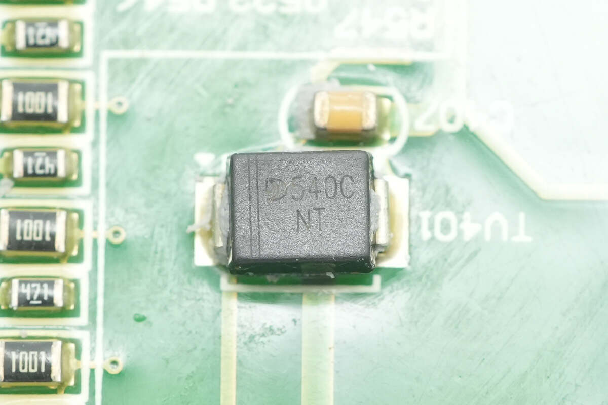
Another TVS diode is also marked with "540C".
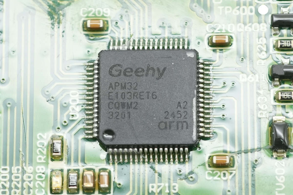
The MCU is from Geehy, model APM32E103RET6. It features an ARM Cortex-M3 core running at 120 MHz, with 512 KB of flash memory and 128 KB of SRAM. It supports interfaces including USART, I2C, SPI, USB, CAN, SDIO, and eMMC, and comes in an LQFP-64 package.
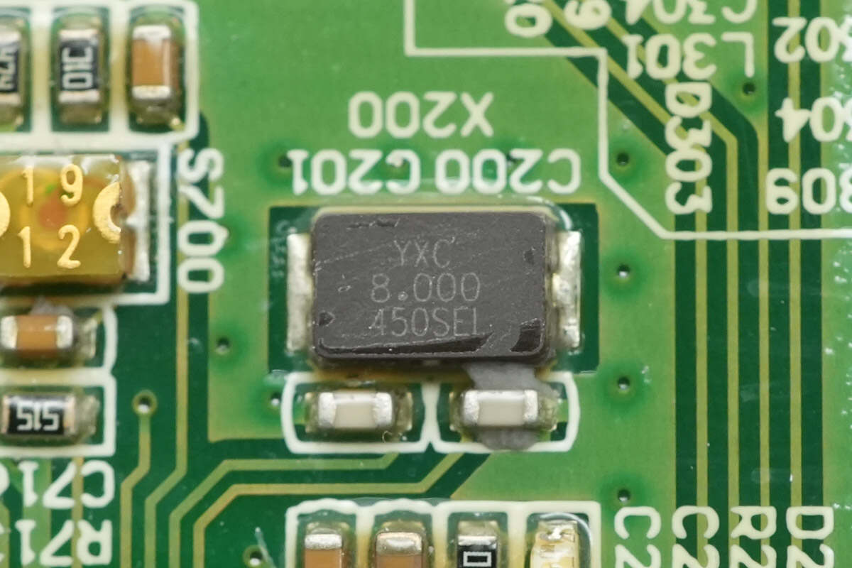
The clock crystal is from YXC with a frequency specification of 8.000 MHz.
Close-up of the angle switch.
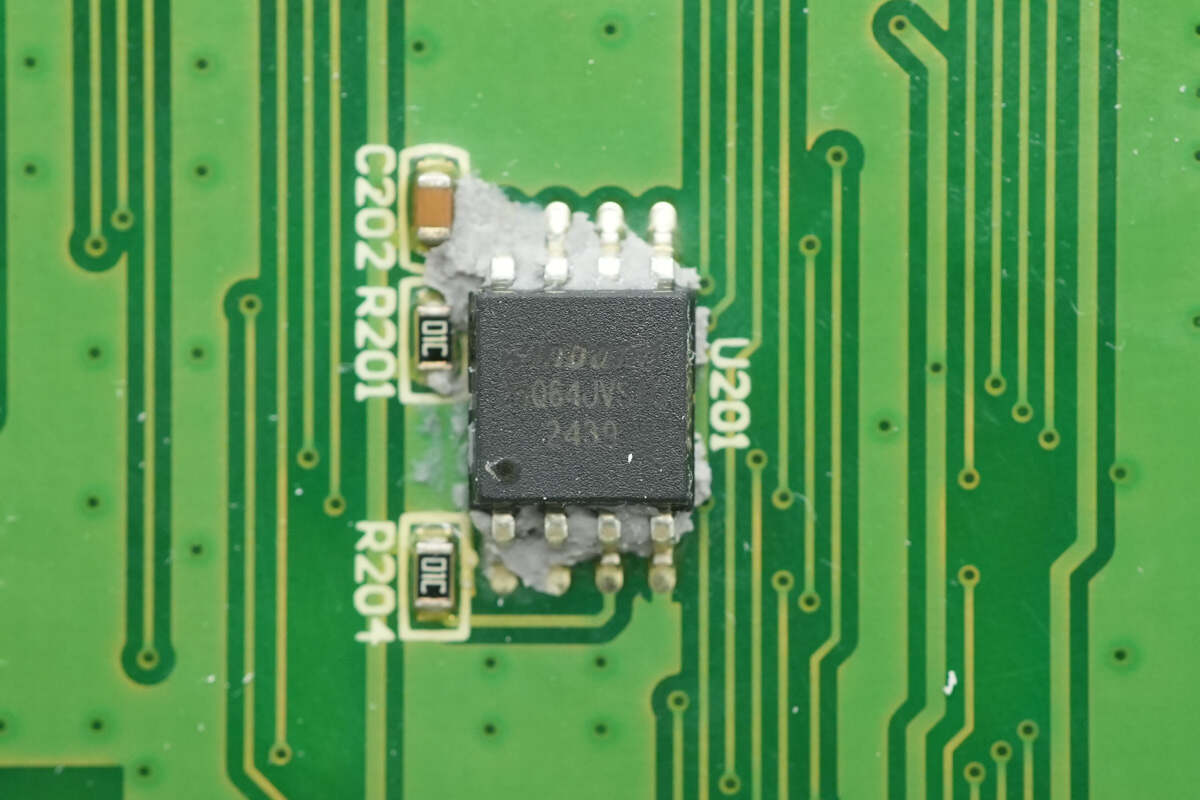
The memory chip is from Winbond, model W25Q64JVSSIQ, with a capacity of 8MB, packaged in SOP-8.
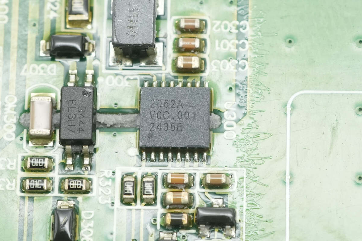
The isolated communication chip for CAN bus is from CHIPANALOG, model CA-IS2062A. It supports 2.5KVrms isolation and features an integrated isolated power supply, eliminating the need for an external isolated power source and simplifying circuit design. It supports CAN communication speeds up to 1Mbps and CAN FD speeds up to 5Mbps, operates within a 2.5 to 5.5V supply range, and comes in an LGA-16 package.
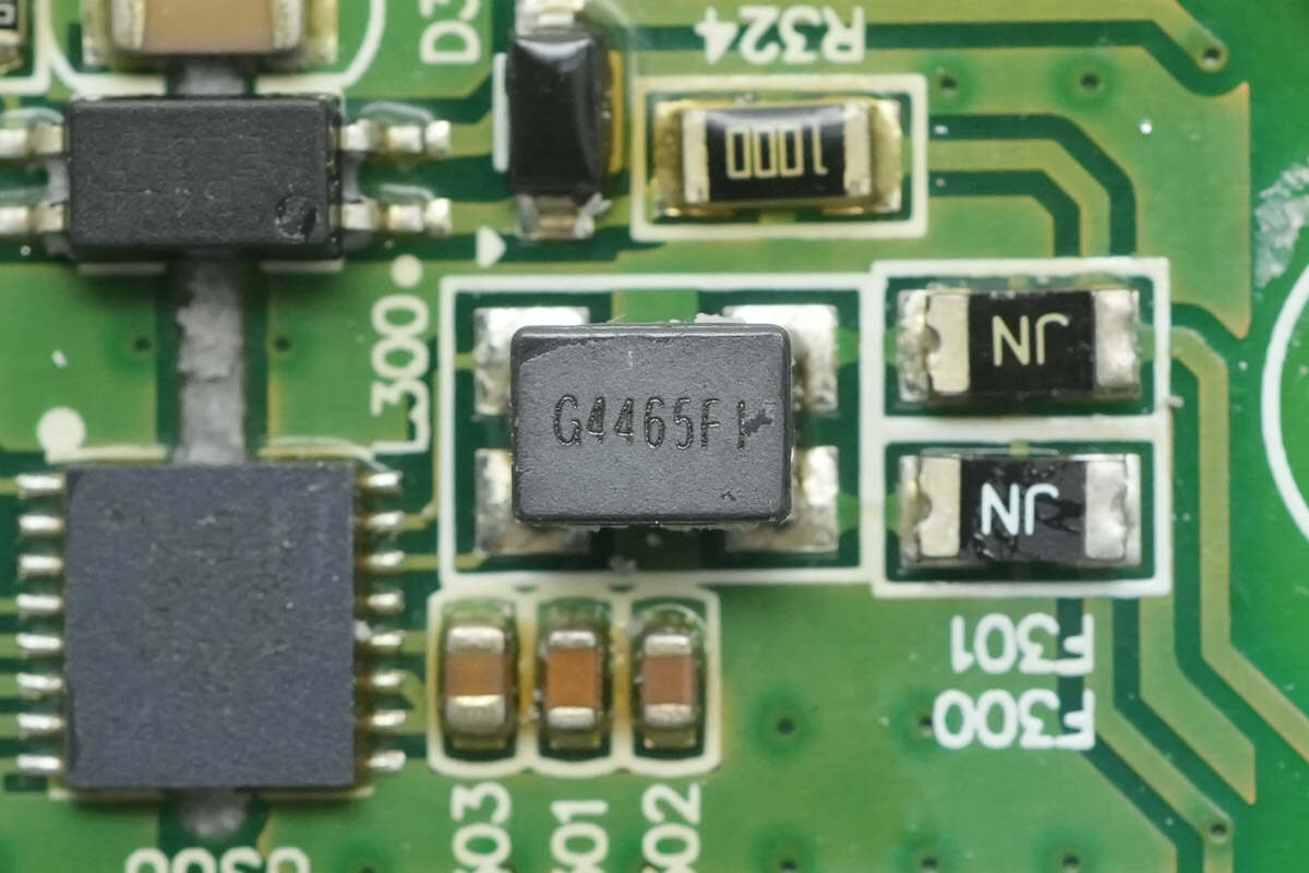
Close-up of the common mode choke used for data line communication filtering.
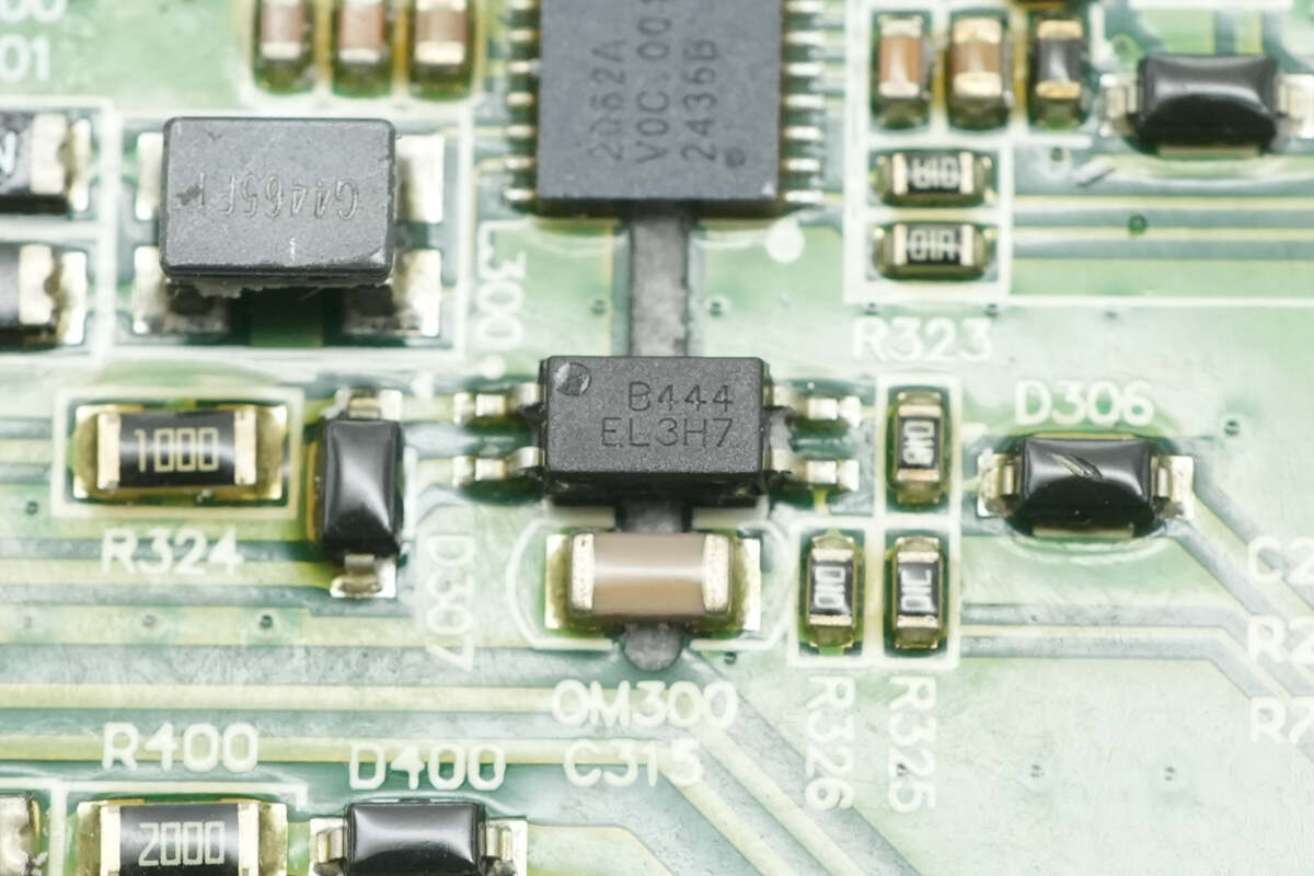
The Everlight EL3H7 optocoupler controls the load resistor.
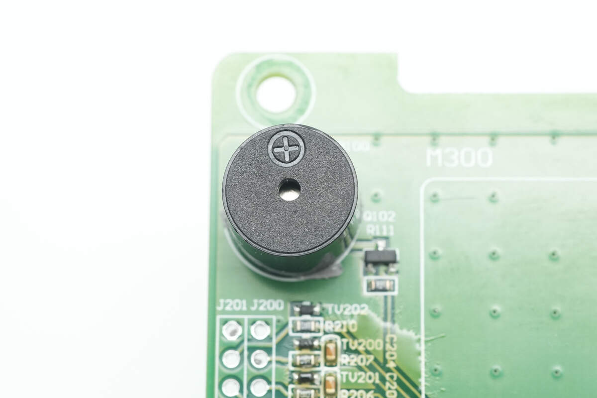
The buzzer is used for alarm notifications.
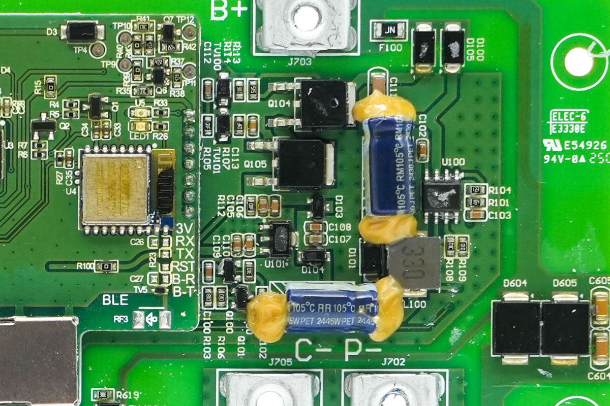
Close-up of the input buck power supply circuit.
The positive input terminal is equipped with a fuse and reverse polarity protection diodes.
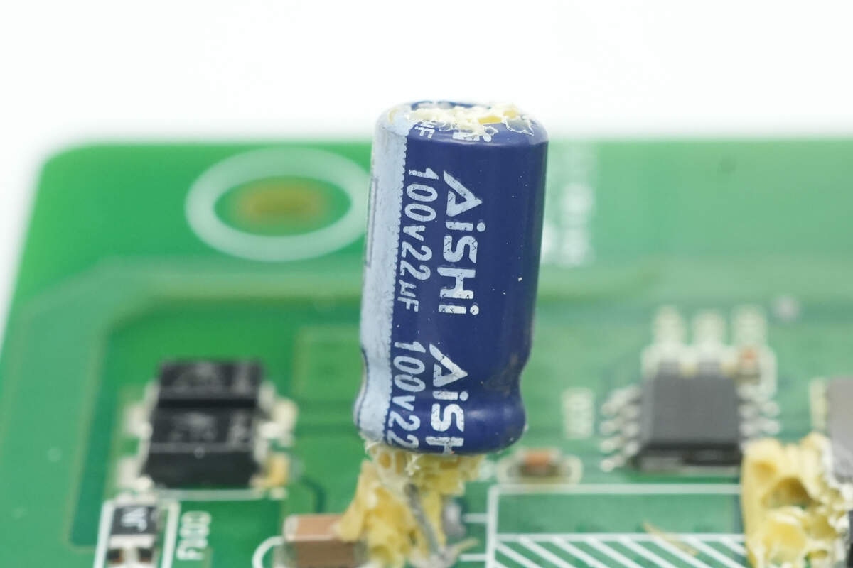
The input filter capacitor is from AiSHi, rated at 100V and 22μF.
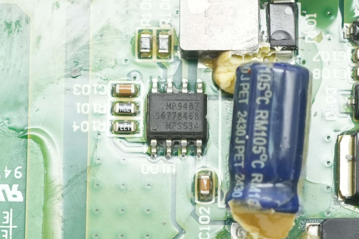
The buck converter chip is from MPS, model MP9487. It supports a 100V input voltage, delivers 1A output current, and comes in an SOIC-8 EP package.
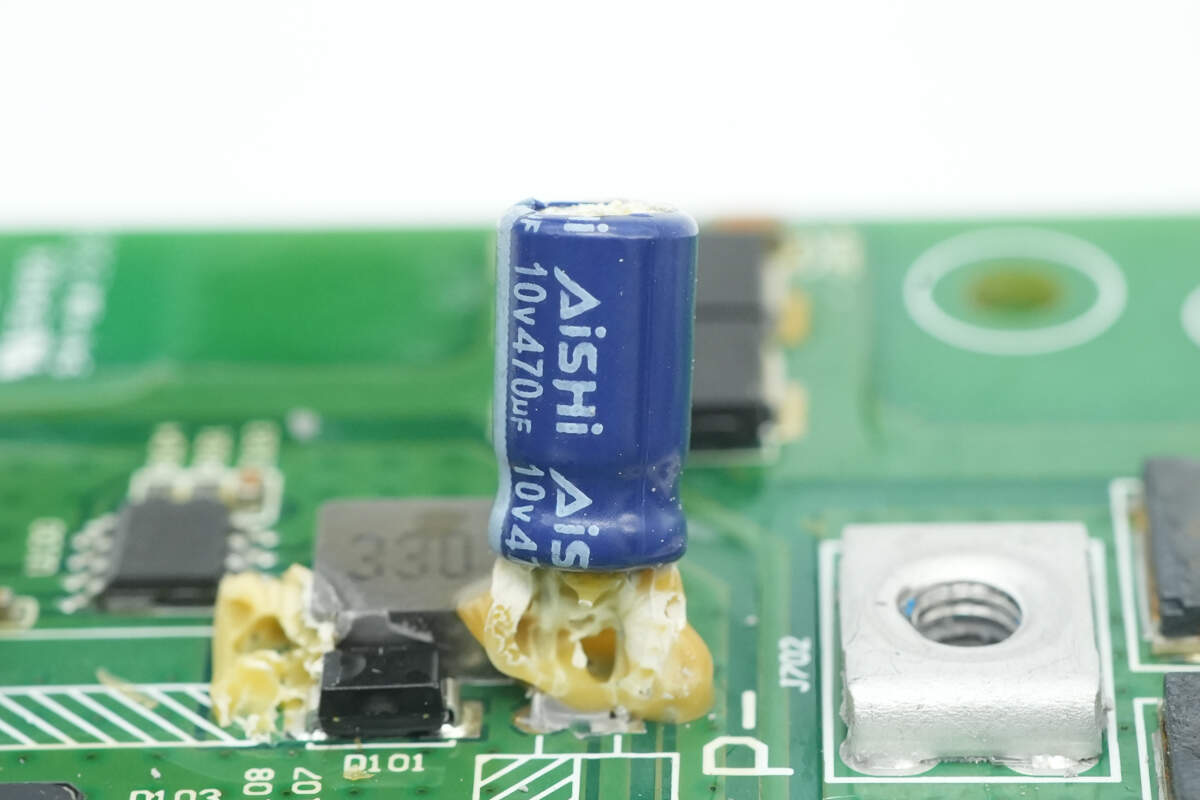
The output filter capacitor is rated at 10V and 470μF.
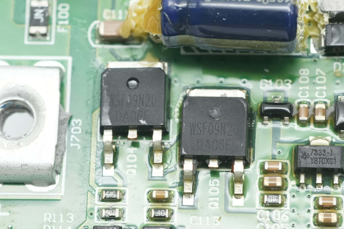
Two WINSOK WSF09N20 MOSFETs are used for power supply buck conversion.
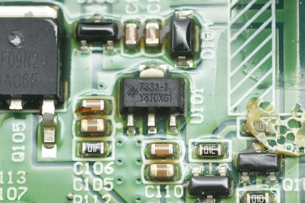
The voltage regulator chip is from Holtek, model HT7333-1. It supports a 30V input voltage, outputs 3.3V at 250mA, and comes in an SOT-89 package.
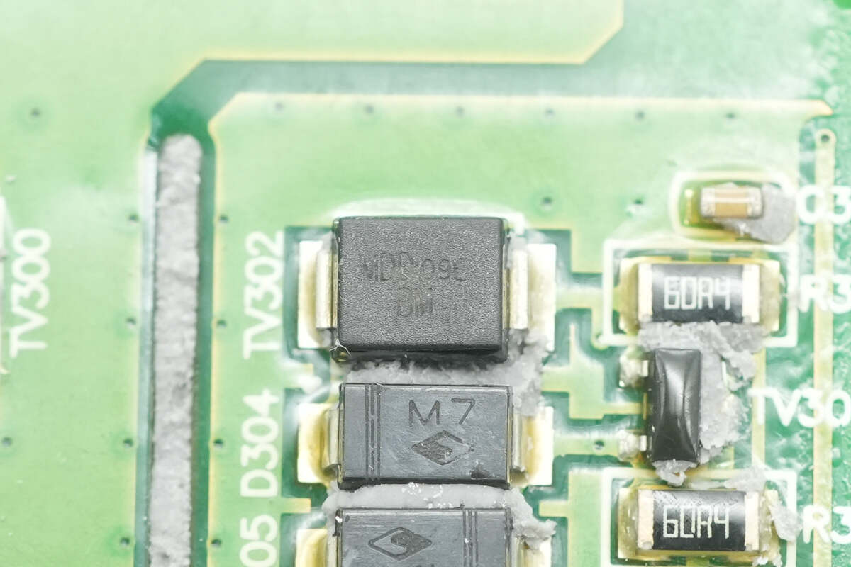
The TVS diode for CAN bus overvoltage protection is from MDD, marked with "BM," model SMBJ15CA. It is a bidirectional TVS with a reverse standoff voltage of 15V and comes in an SMB package.
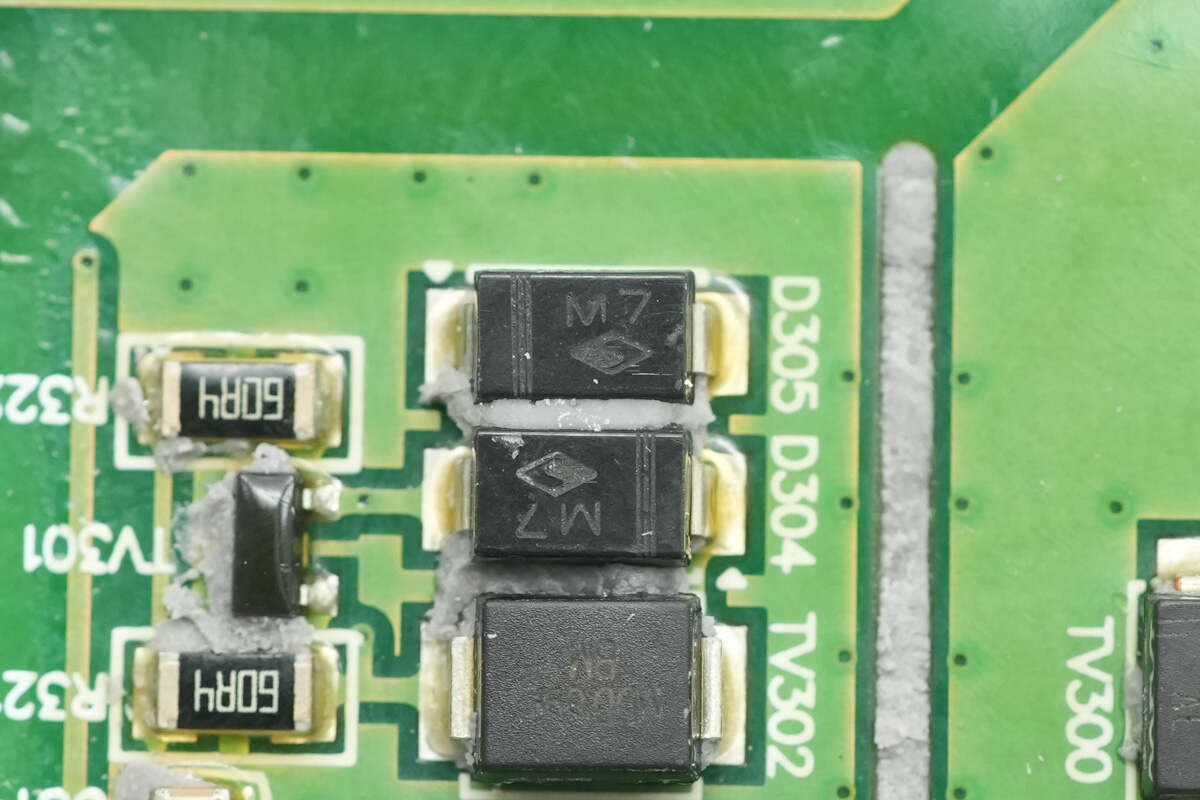
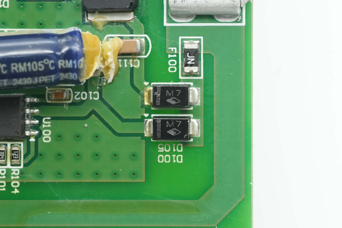
Close-up of two diodes marked with "M7."
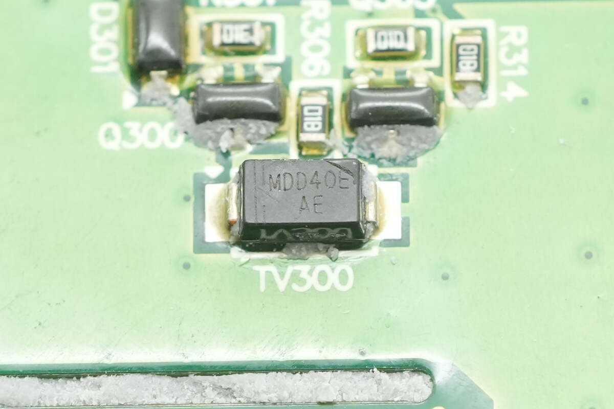
Another TVS diode, marked with "AE," model SMAJ5.0CA, is a bidirectional TVS with a reverse standoff voltage of 5V and comes in an SMA package.
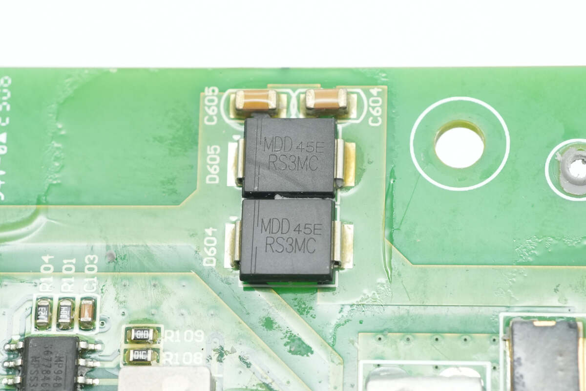
Two reverse polarity protection diodes are from MDD, model RS3MC. They are fast recovery diodes rated at 3A and 1000V, packaged in SMC.
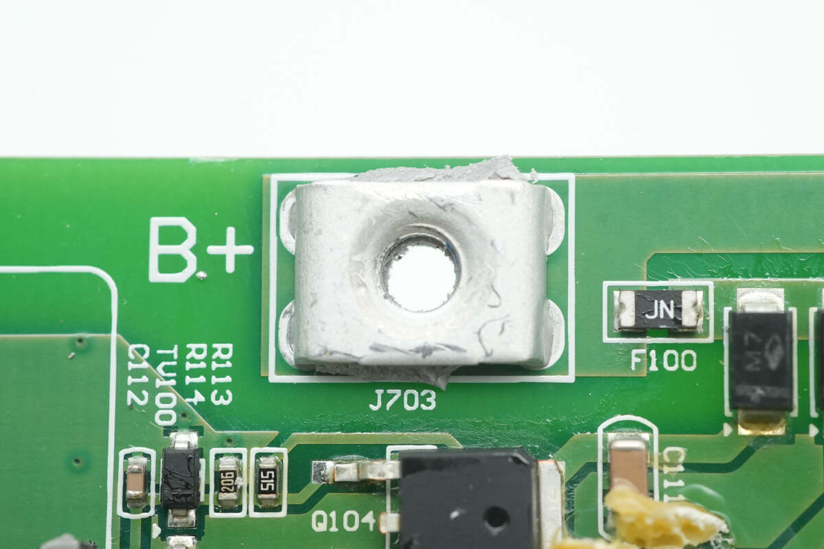
Close-up of the battery pack’s positive terminal post.
Close-up of the negative terminal posts.
Close-up of the output terminal posts.
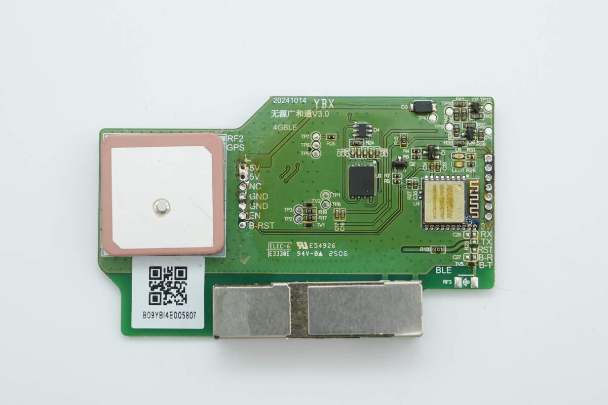
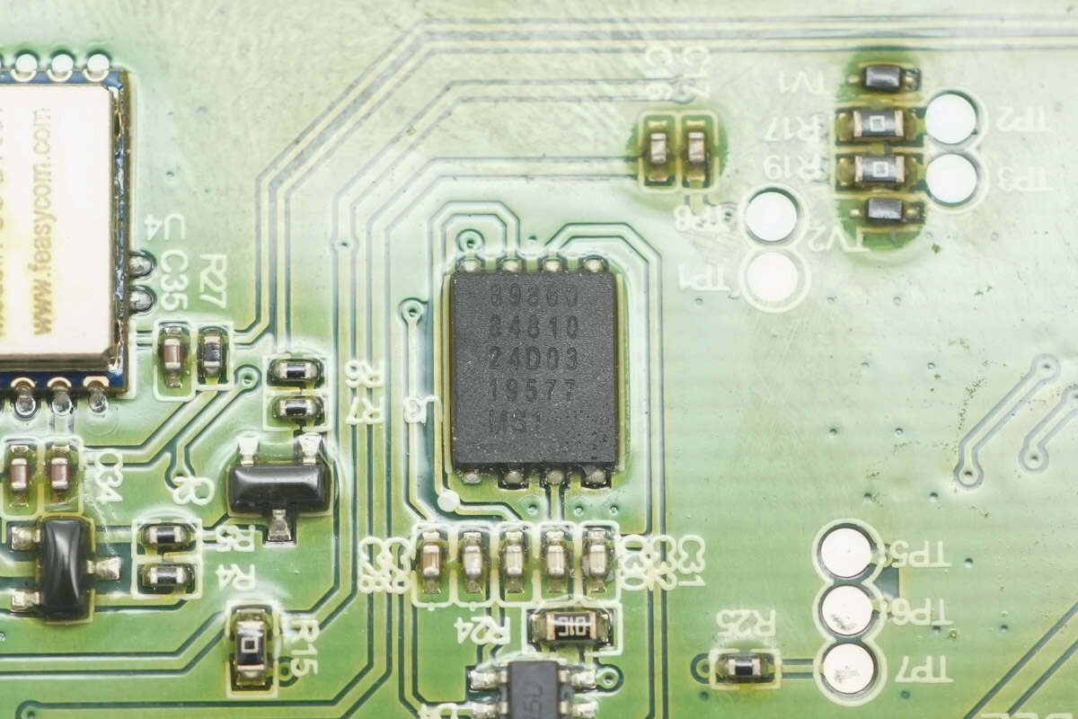
Close-up of the GPS positioning and 4G communication PCB front side, featuring a ceramic GPS antenna, eSIM card, and Bluetooth module.
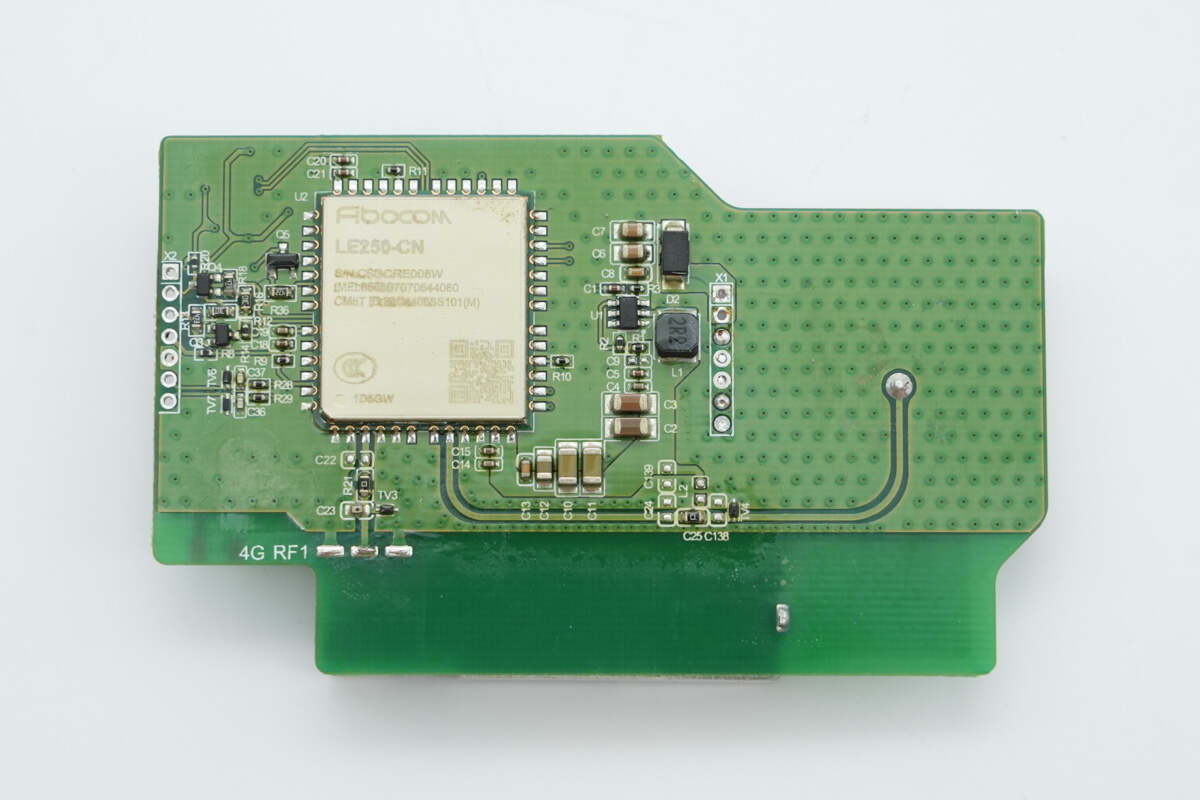
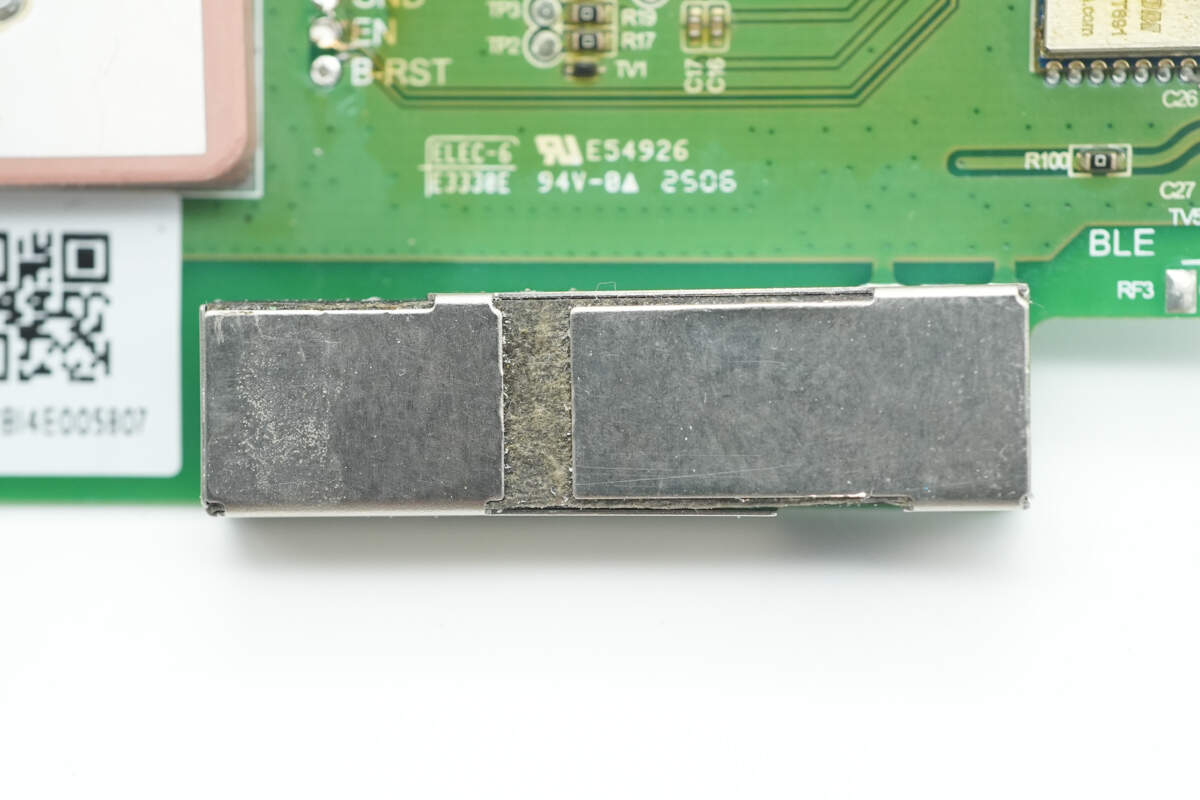
The back side has the wireless communication module.
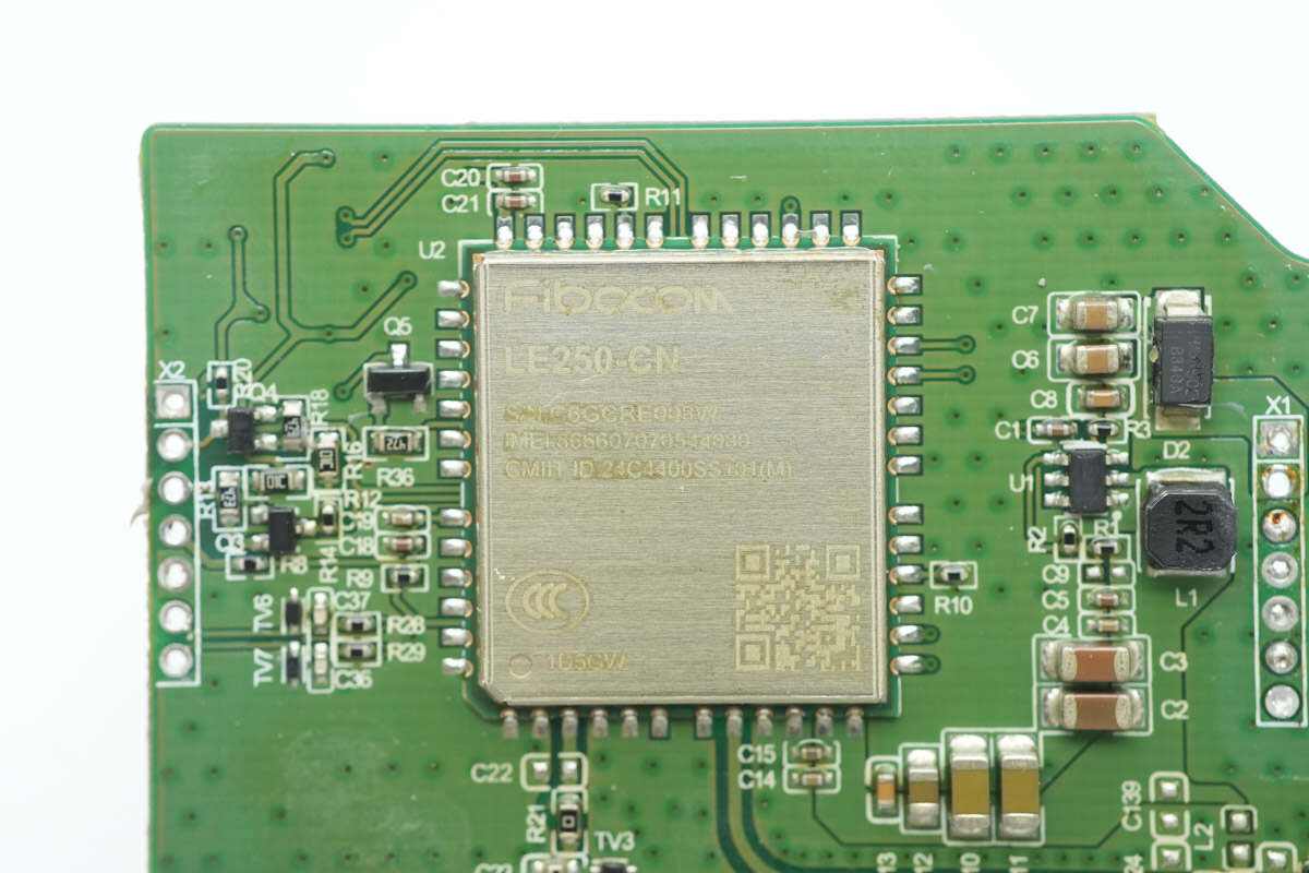
The wireless communication module is from Fibocom, model LE250-CN, supporting 4G communication and GPS positioning functions.
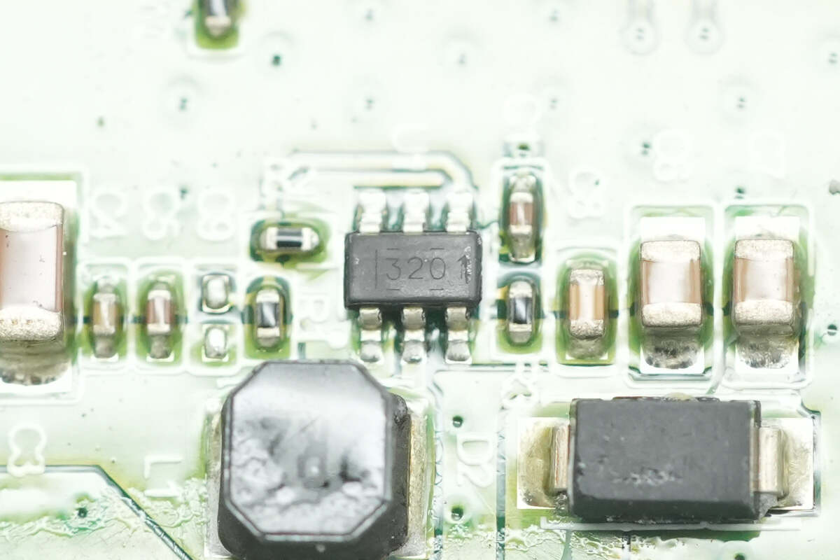
The buck converter chip is from TI, marked with "3201," model TPS563201. It supports an input voltage range of 4.5–17V, delivers 3A output current, and comes in an SOT-23 package.
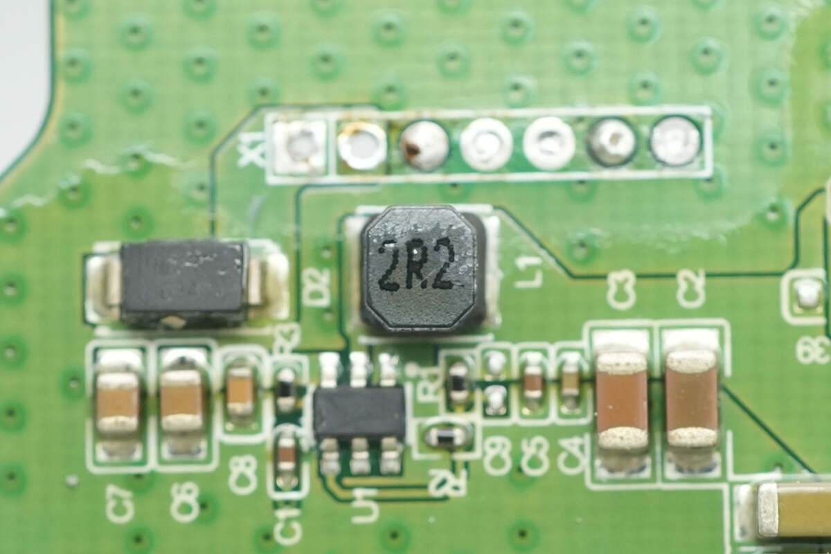
Close-up of the 2.2 μH buck inductor.
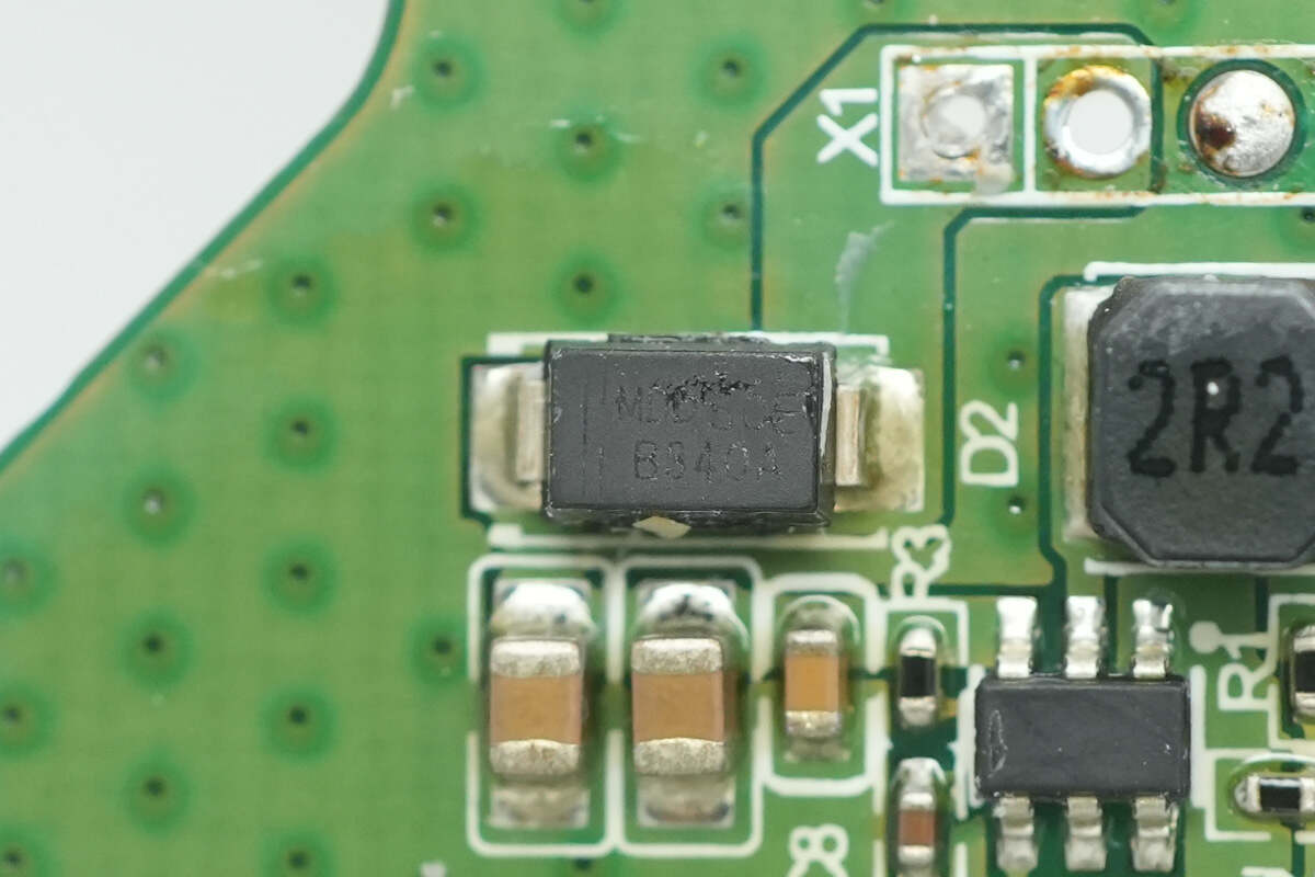
Close-up of the reverse polarity protection diode for the power supply.
Close-up of the eSIM card chip.
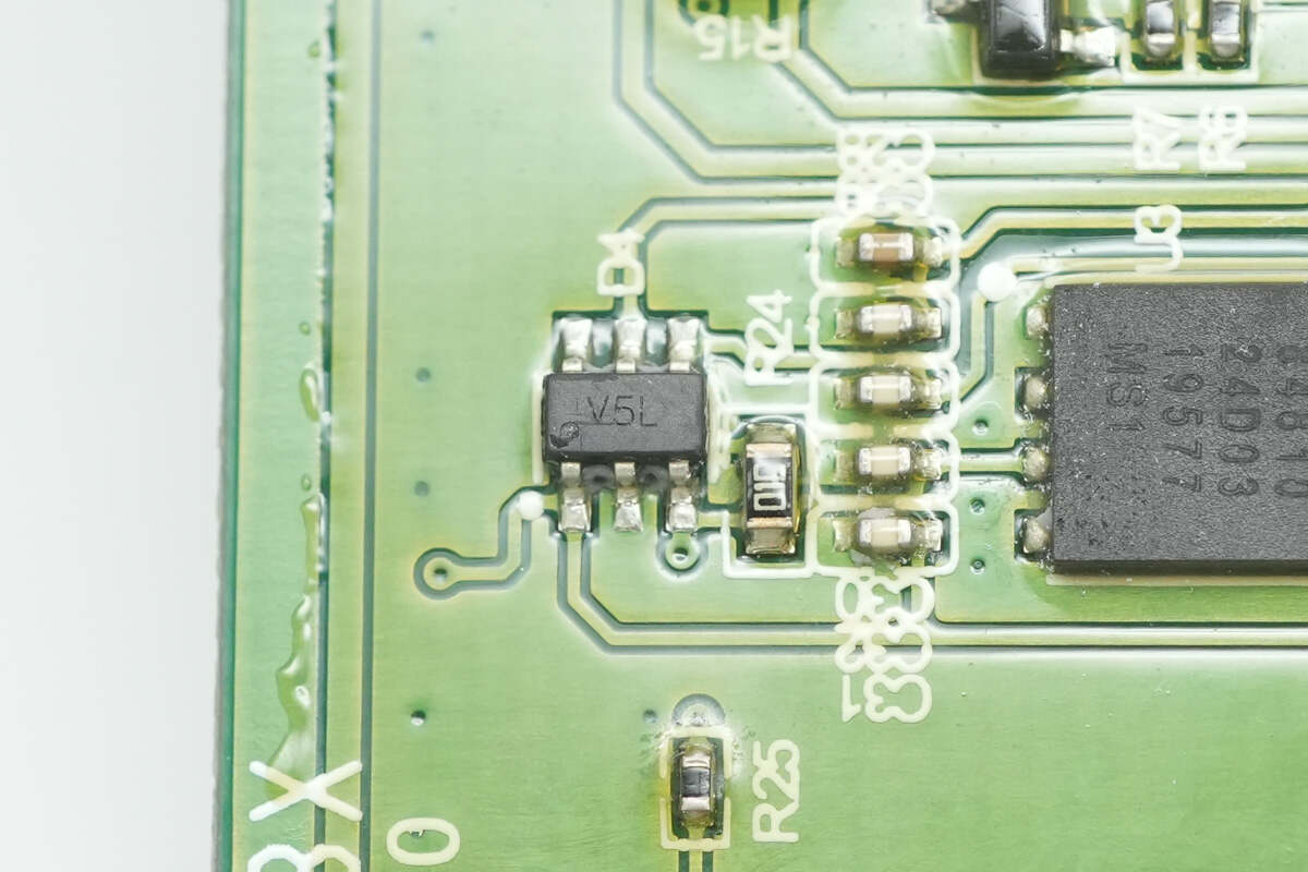
The TVS diode used for overvoltage protection is marked with "V5L."
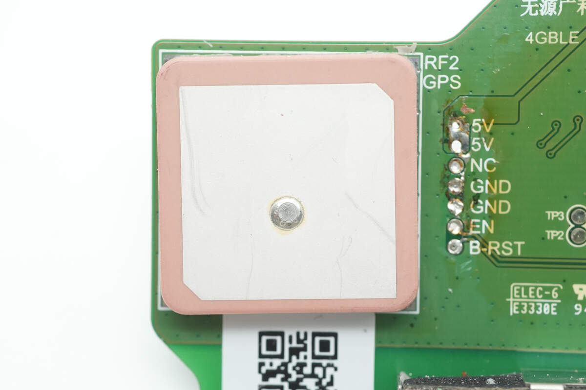
Close-up of the ceramic GPS antenna.
The 4G antenna is connected by soldering.
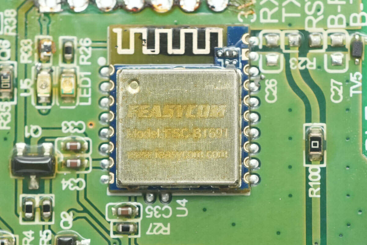
The Bluetooth communication module is from FEASYCOM, model FSC-BT961.
Well, those are all components of the Zhizu 2700Wh Zhiba MAX LiFePO₄ Swappable Battery Pack.
Summary of ChargerLAB
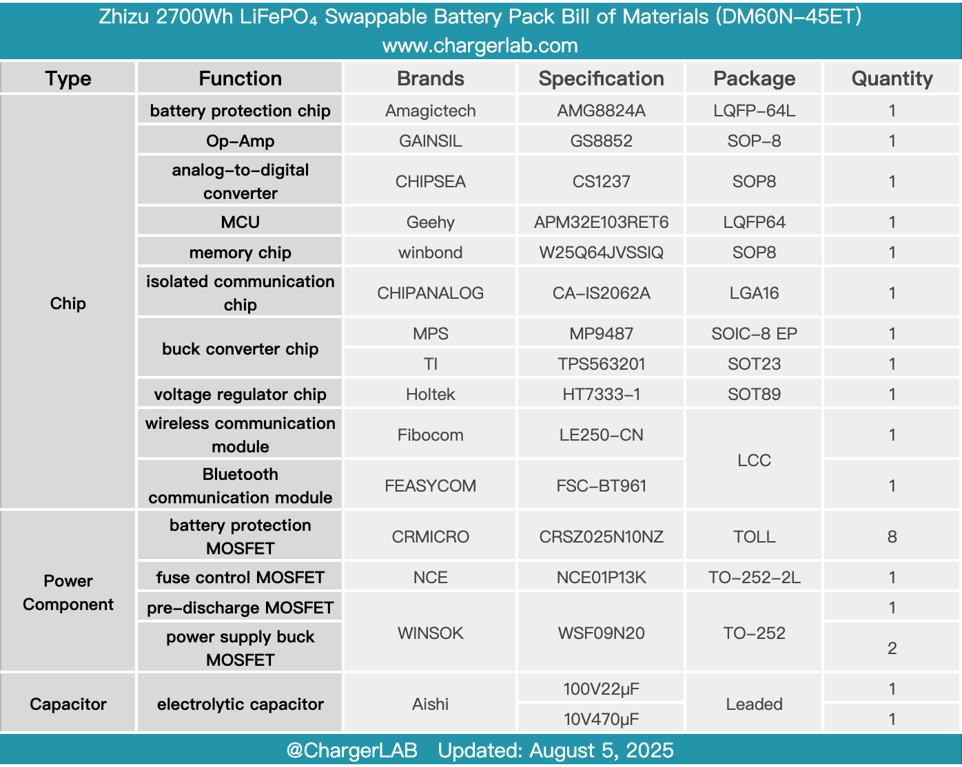
Here is the component list of the Zhizu 2700Wh Zhiba MAX LiFePO₄ Swappable Battery Pack for your convenience.
It contains 20 series-connected lithium iron phosphate cells, with a rated capacity of 45Ah and energy of 2700Wh. It includes a built-in GPS tracking anti-theft system and features a special connector to prevent unauthorized charging.
After taking it apart, we found that the battery protection PCB uses the Amagictech AMG8824A SoC to handle all protection functions, including voltage monitoring, overcurrent protection, cell balancing, capacity measurement, and temperature protection. It also features a Geehy APM32E103RET6 MCU, with a Gainsil op-amp paired with a Chipsea ADC for current sensing. A CHIPANALOG isolation chip is used for CAN communication, and buck converters from MPS and TI are used for the power supply. The battery protection MOSFETs are from CR MICRO, accompanied by three-terminal fuses for overcurrent and fault protection, along with TVS diodes for overvoltage protection. The PCB is coated with conformal insulating paint, and the overall build quality and component selection are solid and reliable.
Related Articles:
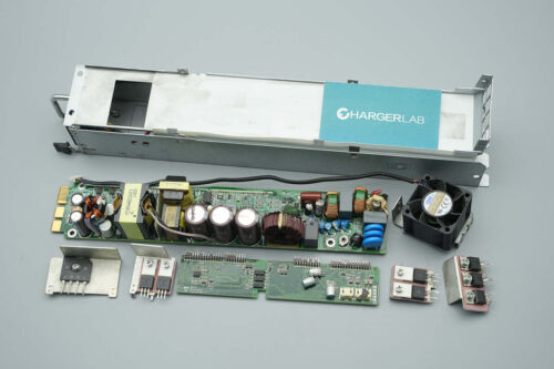
1. Teardown of Dyson Supersonic r 1700W hair dryer (HD17)
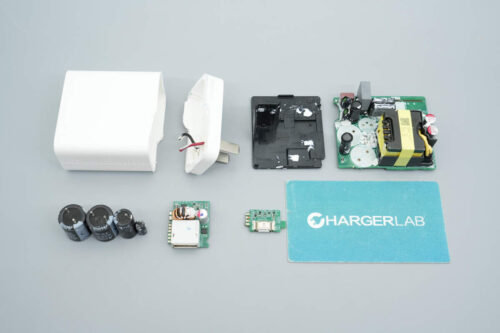
2. Teardown of Delta 300W Triple USB-C AC/DC Power Adapter (ADP-300EB B)
3. Teardown of HONOR 100W GaN Charger for Laptop (HN-200500CP0)