Introduction
This teardown covers the 2026 version of the Xiaomi 10000mAh Magnetic Power Bank with Stand. Compared with the previous model, it complies with 15 items under China’s updated CCC regulations for power banks. It supports quick verification of product health status via an official Xiaomi web link.
The device features a skin-friendly finish with a smooth, refined feel. It integrates a strong magnetic attachment, a multi-angle foldable stand, and an L-shaped built-in cable into a single design.
The product supports up to 33W wired output and 30W wired input, while wireless charging delivers up to 15W peak output. Next, we will take a closer look at the design of this product.
Product Appearance
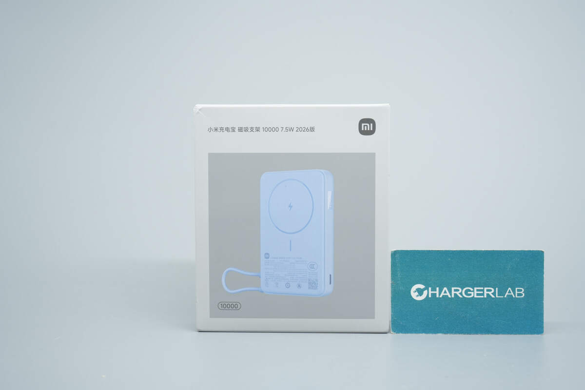
The front of the packaging displays the product name along with a conceptual image of the product’s front design.
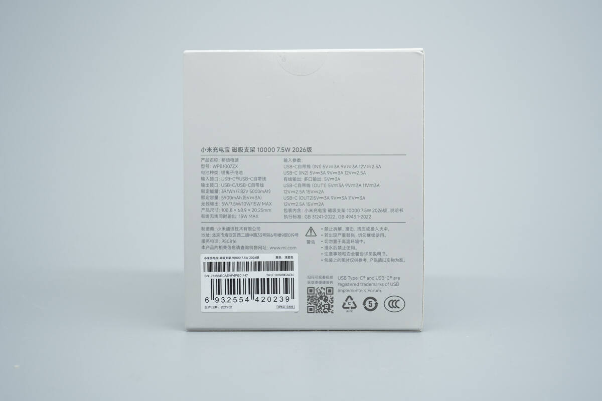
The back of the packaging features specifications, safety information, and warning notices.
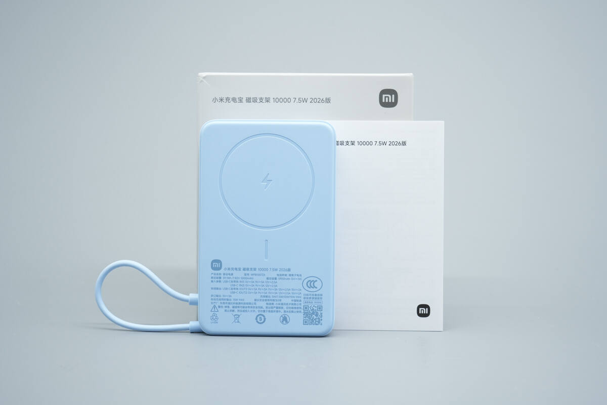
The package includes the power bank and a user manual.
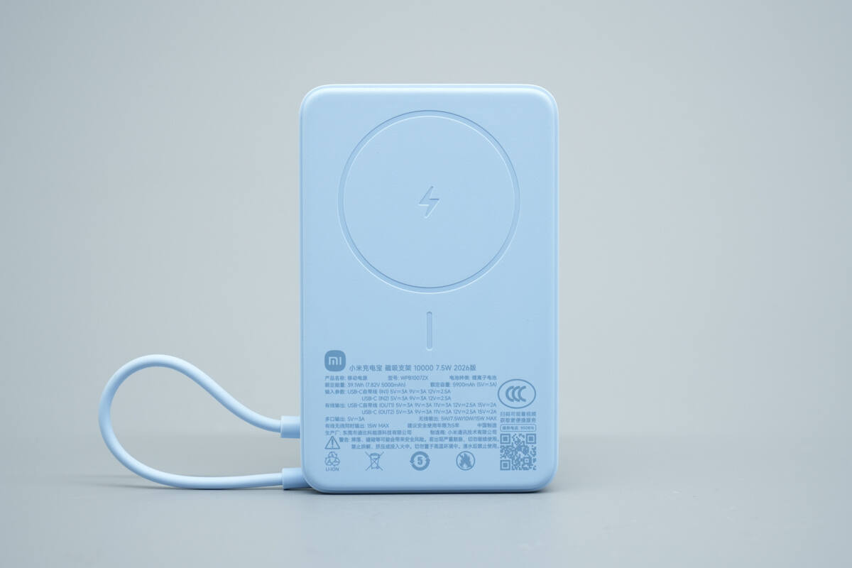
The power bank comes in light blue and features a skin-friendly finish. A lightning icon is printed on the magnetic wireless charging area to indicate the charging zone. An integrated USB-C cable is located on the left side.
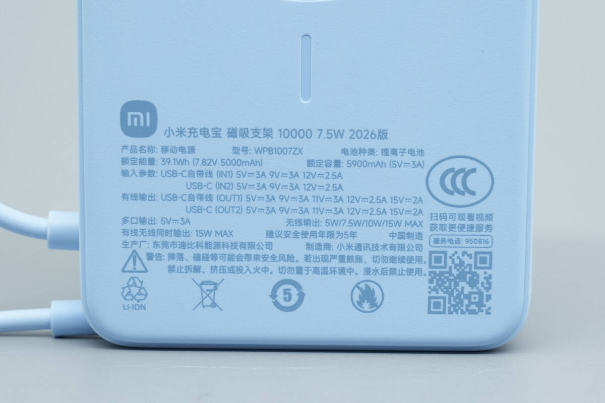
Model: WPB1007ZX
Battery Type: Lithium-ion battery
Rated Energy: 39.1Wh (7.82V 5000mAh)
Rated Capacity: 5900mAh (5V 3A)
Input:
USB-C Integrated Cable (IN1): 5V 3A, 9V 3A, 12V 2.5A
USB-C (IN2): 5V 3A, 9V 3A, 12V 2.5A
Wired Output:
USB-C Integrated Cable (OUT1): 5V 3A, 9V 3A, 11V 3A, 12V 2.5A, 15V 2A
USB-C (OUT2): 5V 3A, 9V 3A, 11V 3A, 12V 2.5A, 15V 2A
Wireless Output:
5W / 7.5W / 10W / 15W Max
Multi-port Output:
5V 3A (wired + wireless)
Simultaneous Output:
15W Max
This product has passed CCC certification.
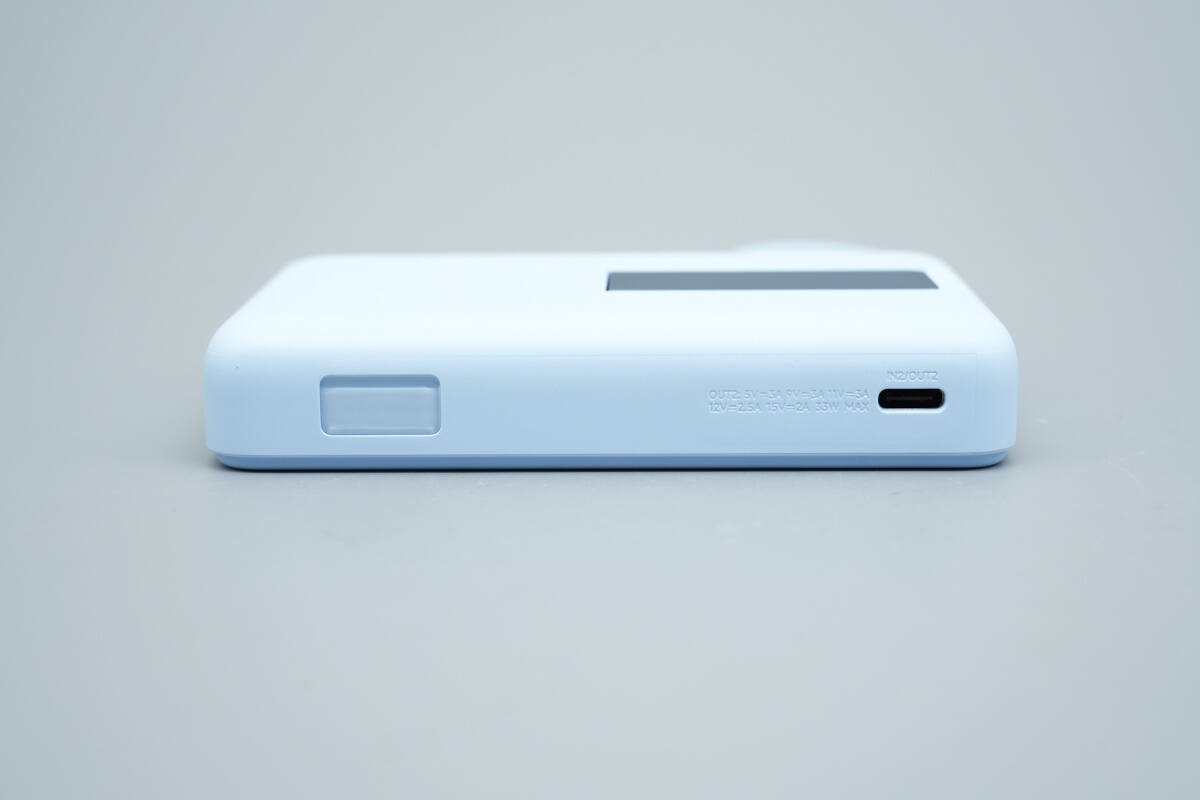
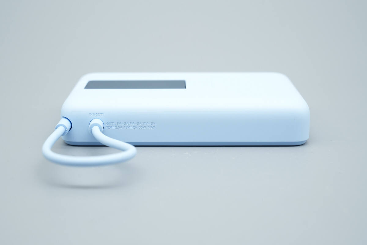
This side features a digital display and a USB-C port.
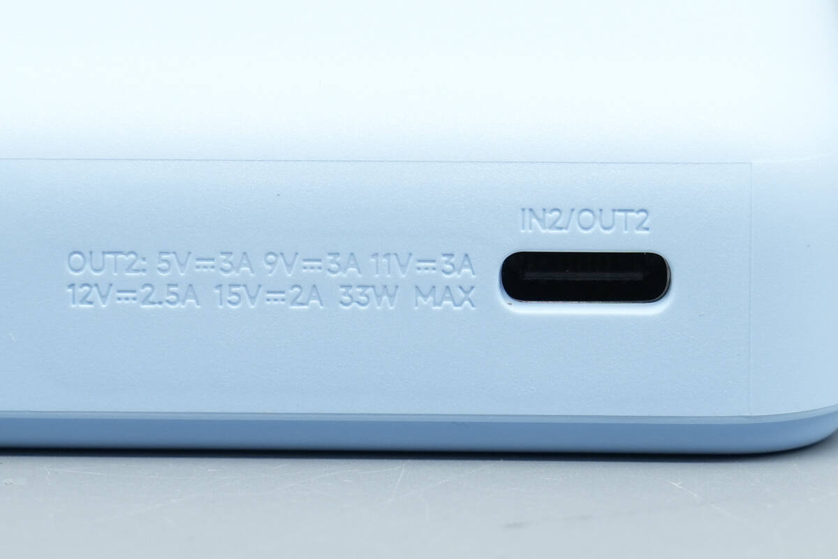
Text printed beside the port indicates that it supports up to 33W for both input and output.
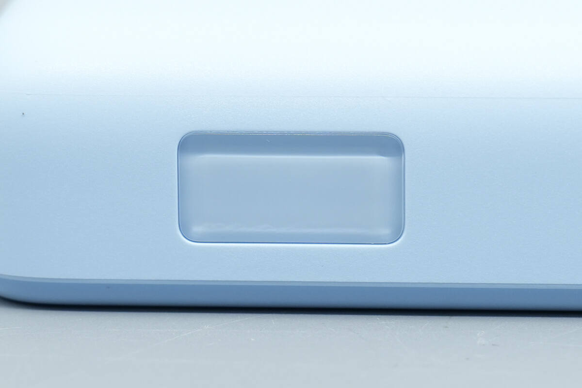
A close-up of the hidden LED digital display area, covered by a semi-transparent protective shell.
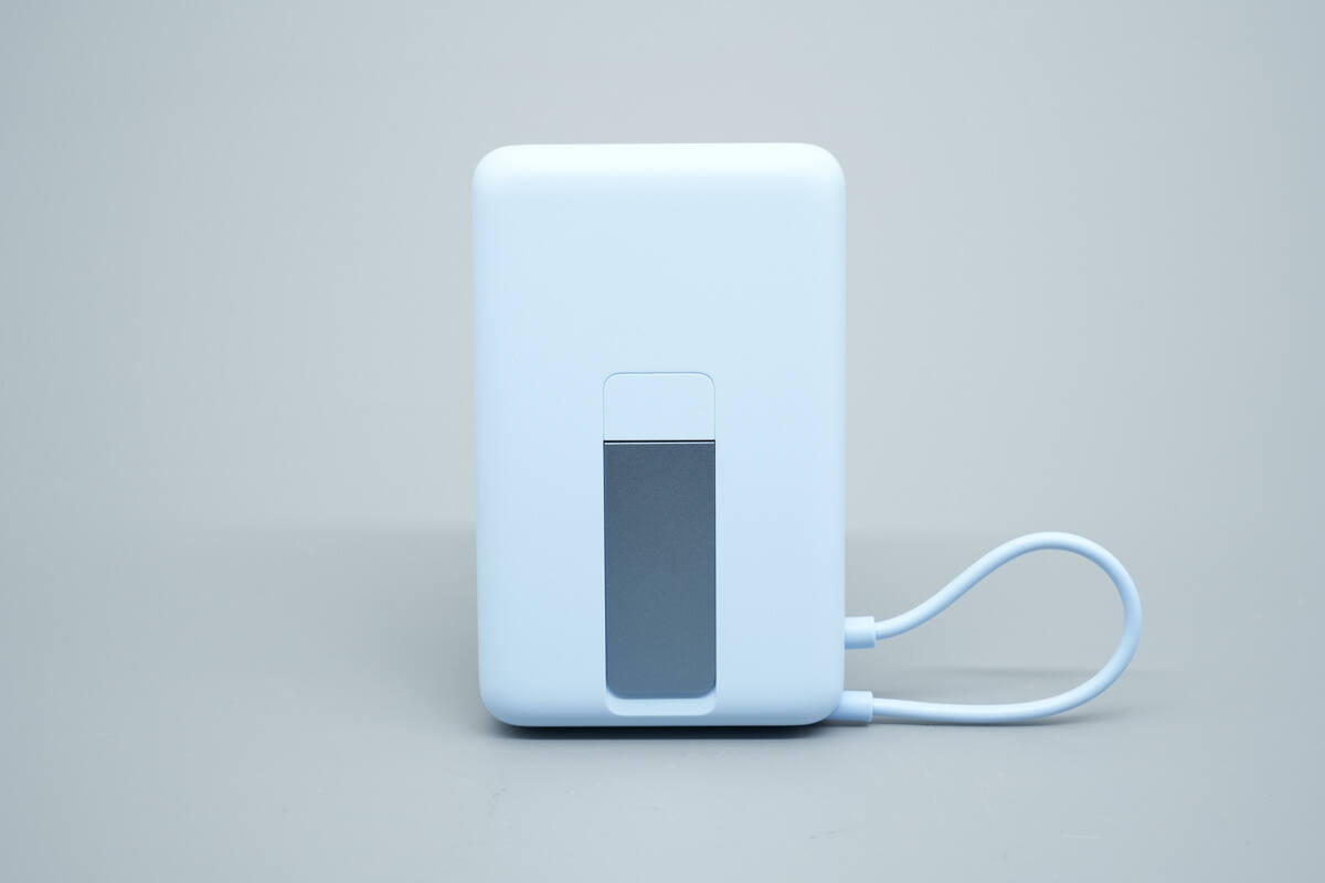
On the back of the power bank, a dark gray metal foldable stand is embedded in the center.
On the opposite side, the integrated cable is visible, which also supports up to 33W power.
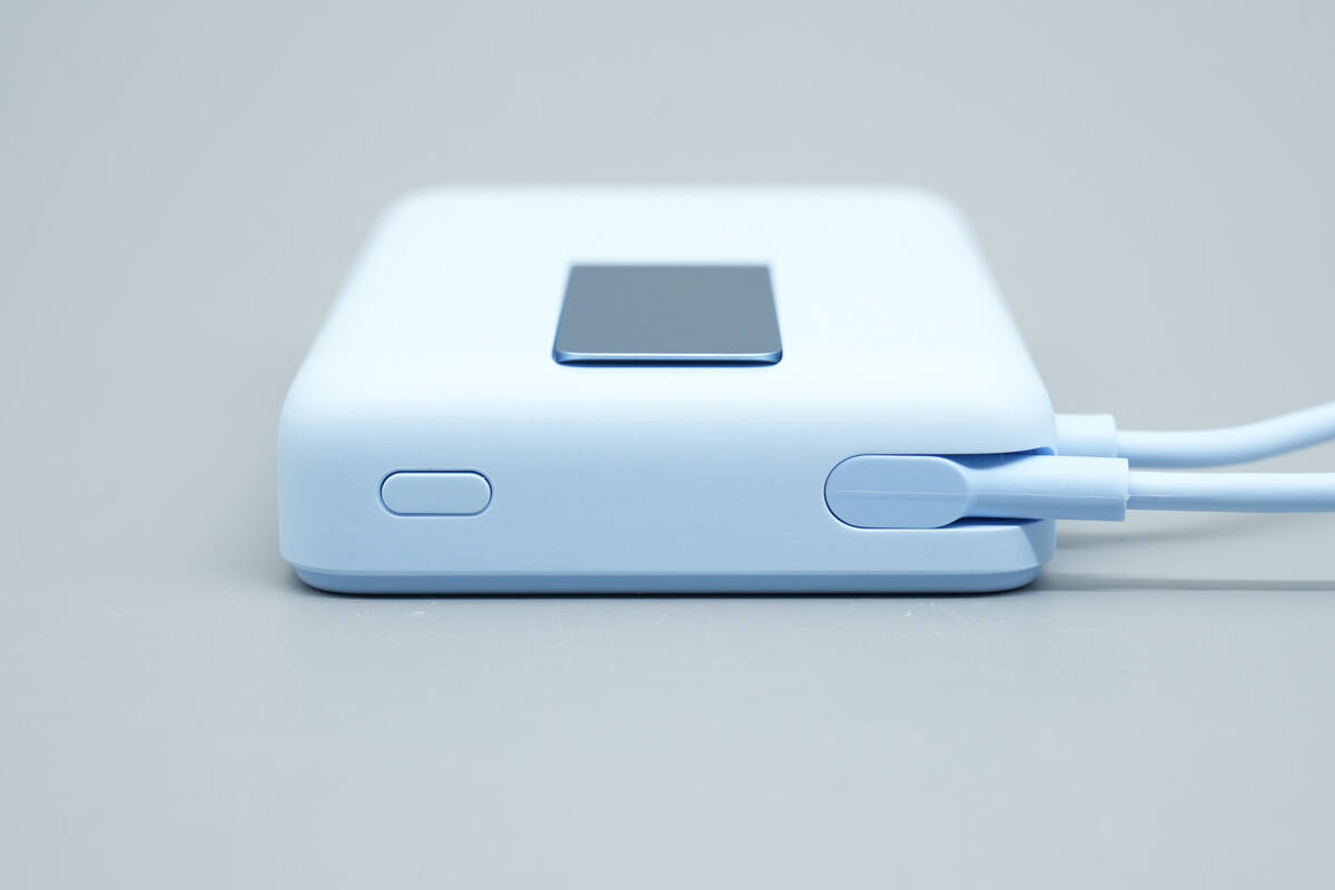
A power button is located at the bottom of the power bank.
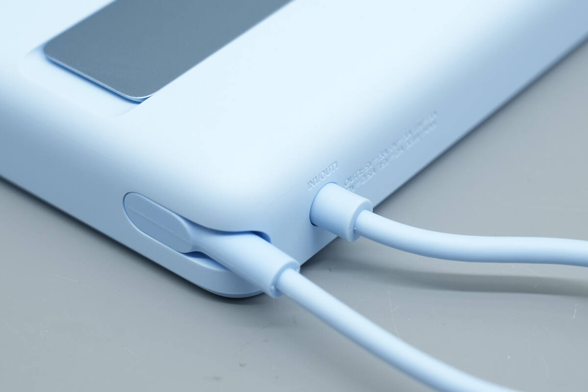
The integrated cable in its stored position fits perfectly into the side groove, as shown in the image.
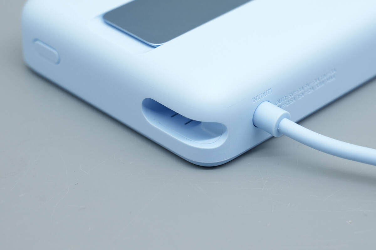
After removing the integrated cable, the slot structure becomes visible.
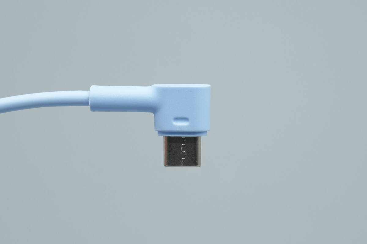
The integrated cable features an L-shaped connector at its tip.
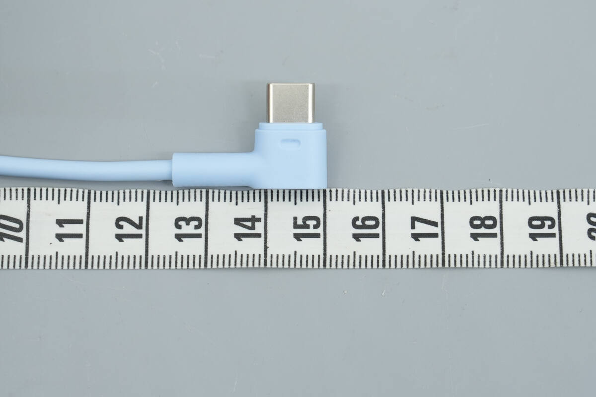
The length of the cable is about 15 cm (5.91 inches).
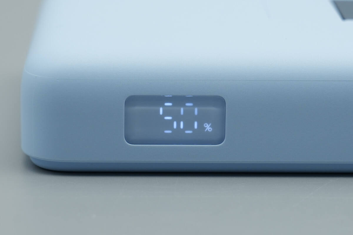
Pressing the power button lights up the side digital display, showing the remaining battery level at 50%.
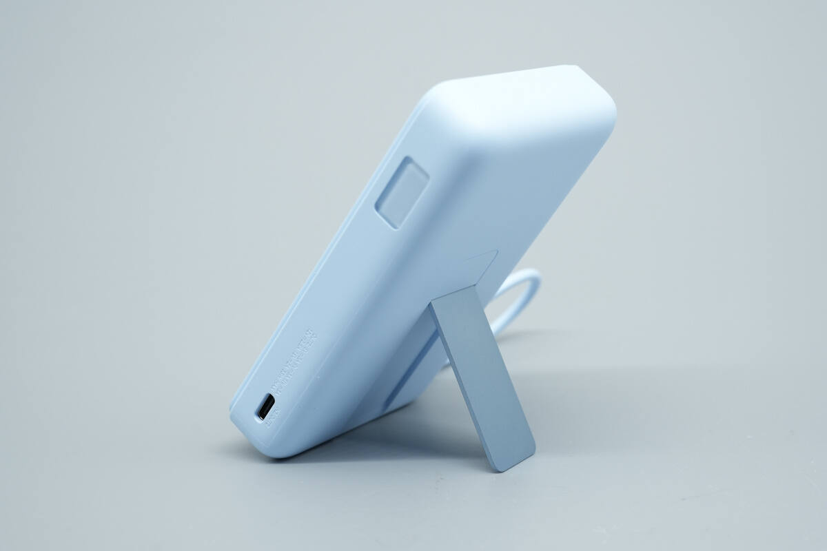
When the metal stand is unfolded, the power bank can stand stably on a desk.
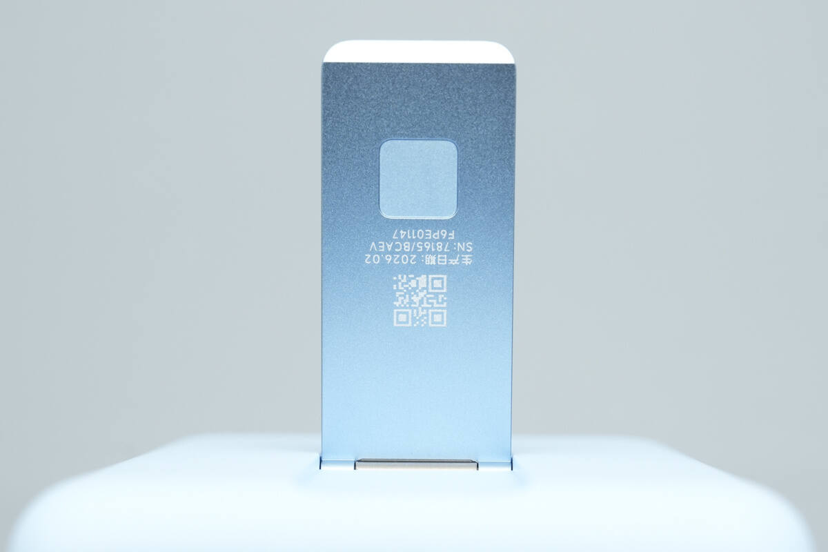
The inner side of the metal stand is printed with the product’s manufacturing date, serial number, and a QR code.

ChargerLAB POWER-Z KM003C shows that the USB-C cable supports PD3.0, PPS, QC4, and DCP charging protocols.
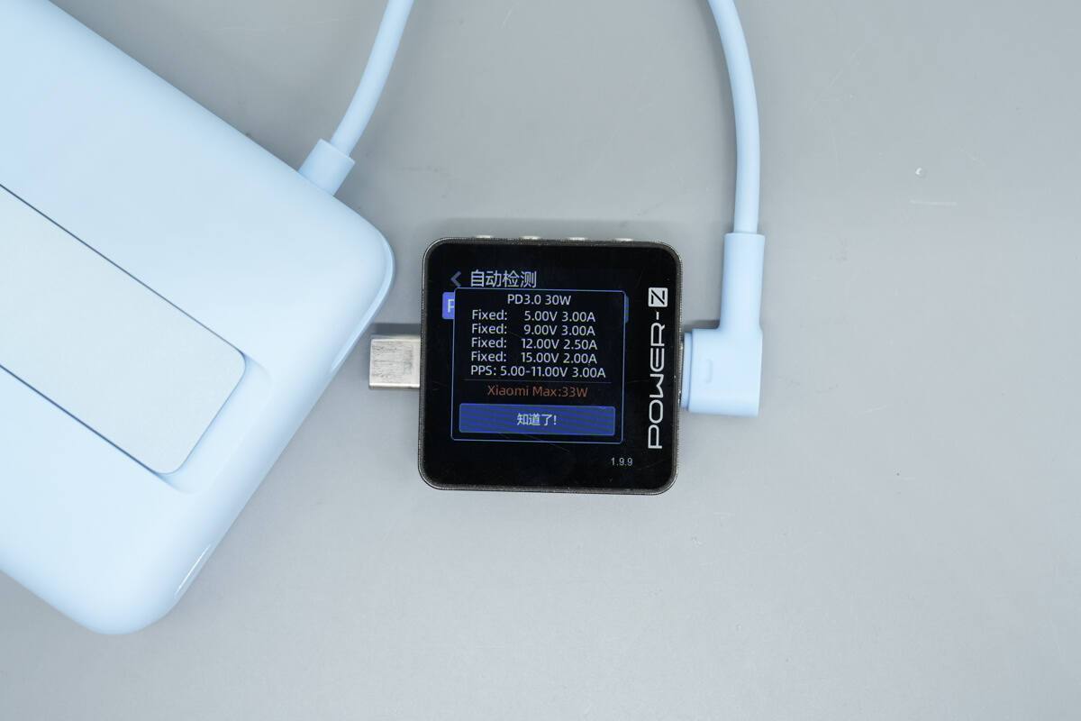
It also supports four fixed PDOs of 5V 3A, 9V 3A, 12V 2.5A, and 15V 2A, as well as a PPS voltage range of 5–11V 3A, and additionally supports Xiaomi’s proprietary 33W fast charging.
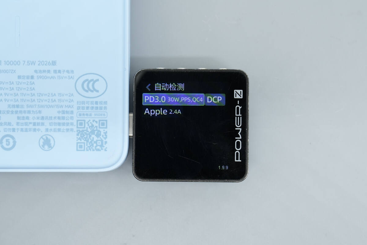
ChargerLAB POWER-Z KM003C shows that the USB-C port supports PD3.0, PPS, QC4, DCP, and Apple 2.4A charging protocols.
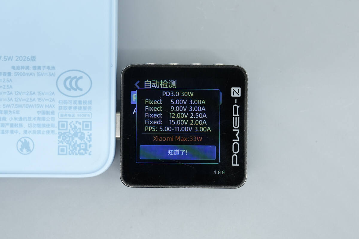
The PDO configuration is the same as that of the integrated cable.
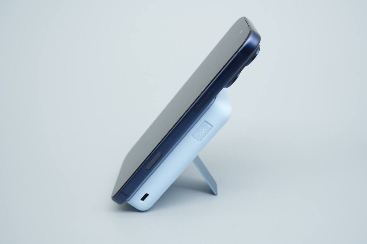
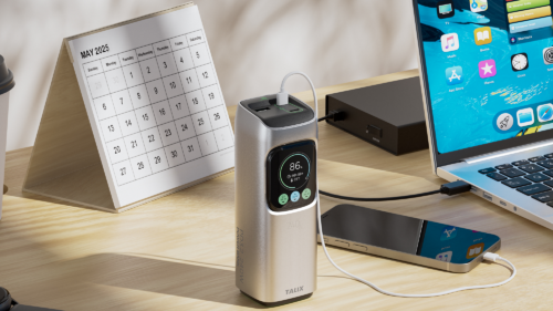
Simulating a daily usage scenario, an iPhone magnetically attaches to the power bank while the stand is unfolded.
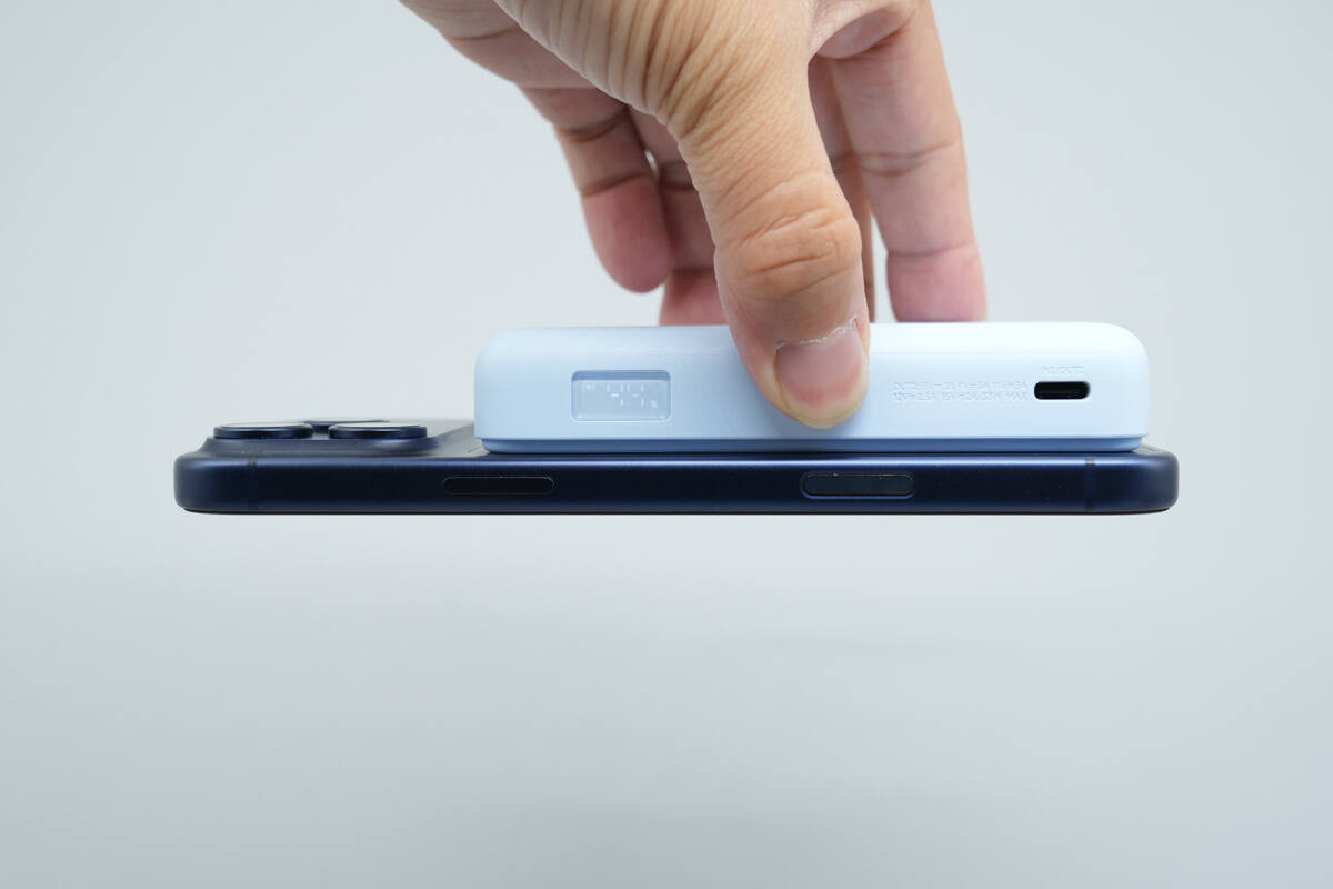
The magnetic force can easily lift a smartphone without it falling off.
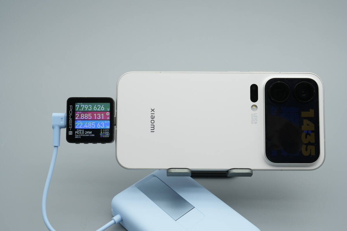
Charging a Xiaomi smartphone using the integrated cable, the charging power is about 22.48W.
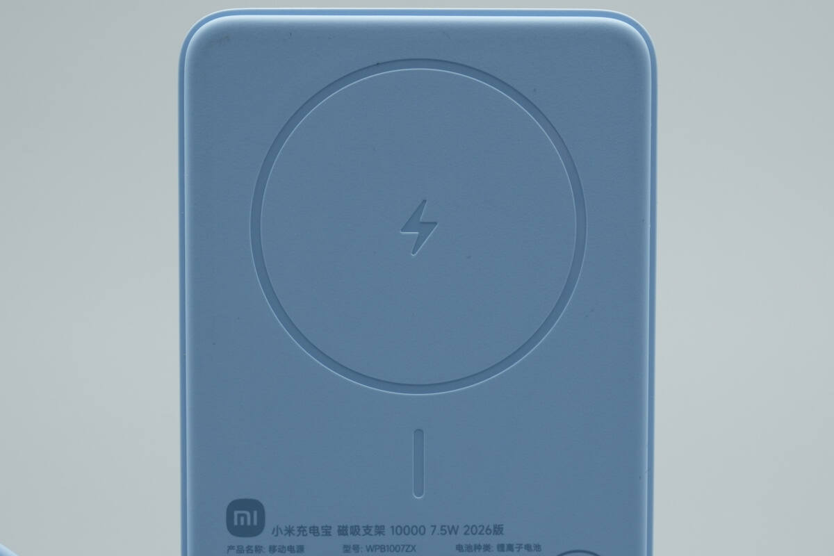
The wireless charging surface features a fine texture, effectively preventing scratches on the back of the phone.
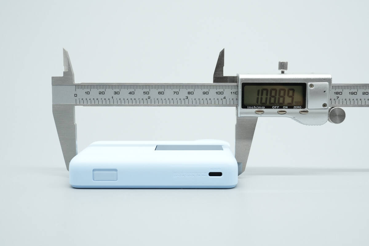
The length of the power bank is about 108.89 mm (4.29 inches).
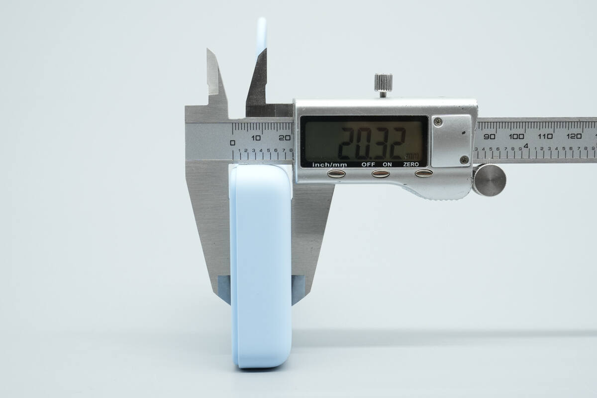
The thickness is about 20.32 mm (0.8 inches).
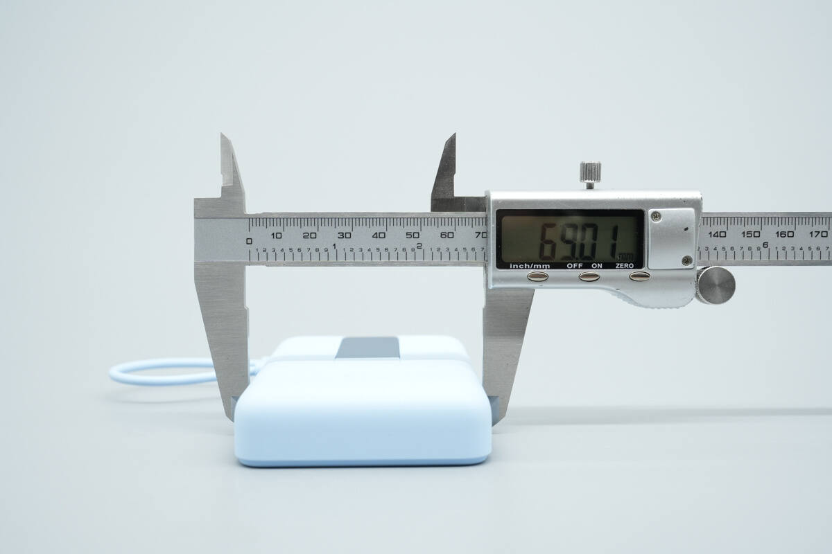
The width is about 69.01 mm (2.72 inches).
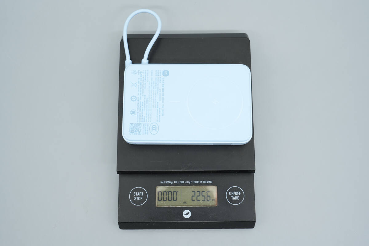
The weight is about 225.6 g (7.96 oz).
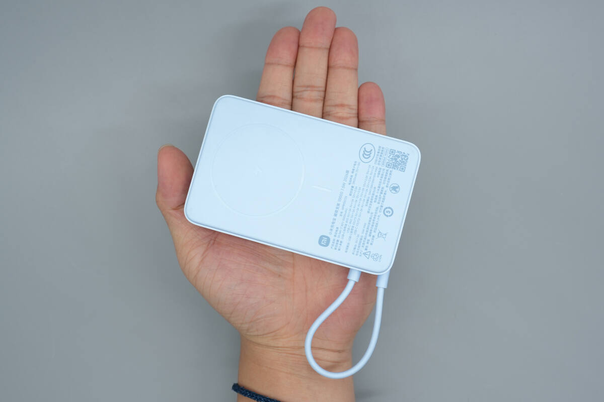
That's how big it is in the hand.
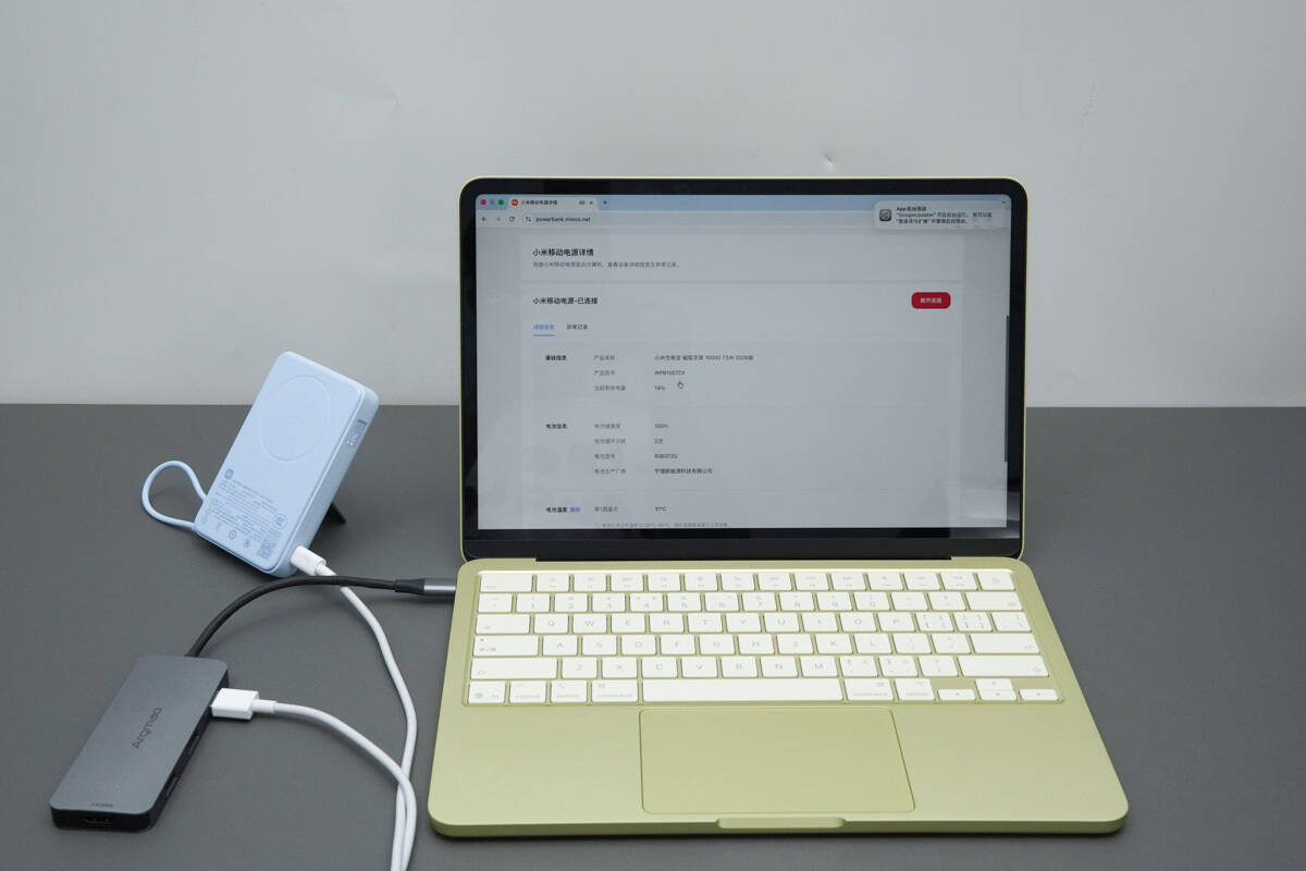
By connecting it to a computer and using the official Xiaomi web portal, users can quickly check the actual battery health of the product.
Teardown
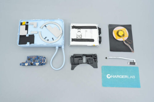
Next, let's take it apart to see its internal components and structure.
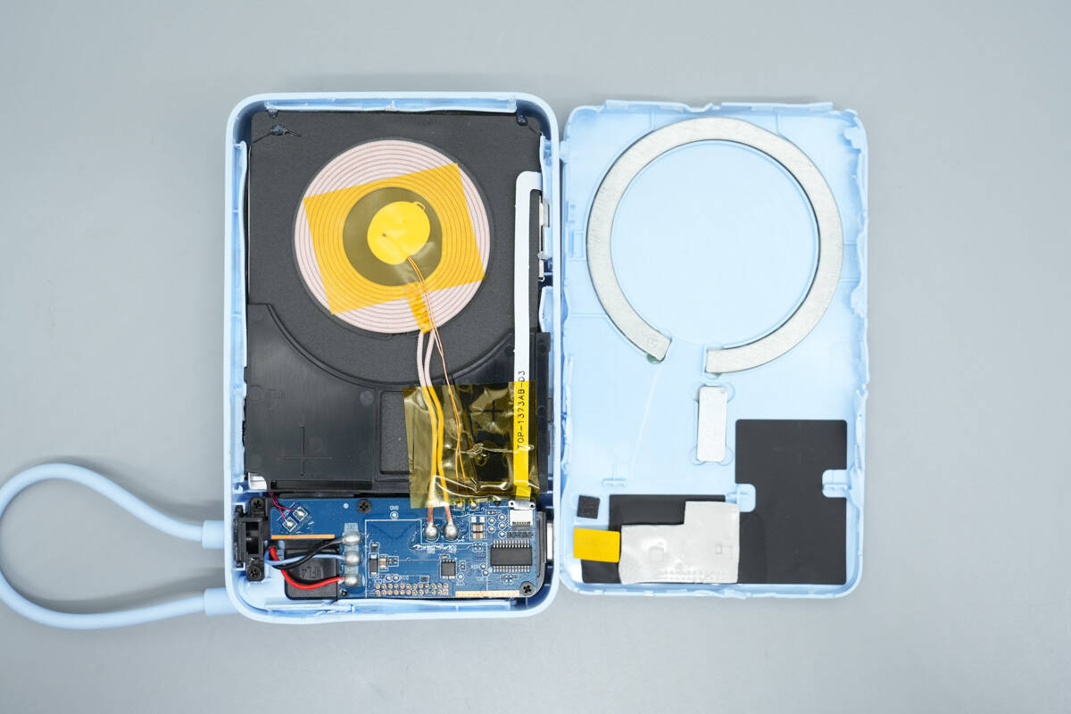
Pry open the front panel along the seam.
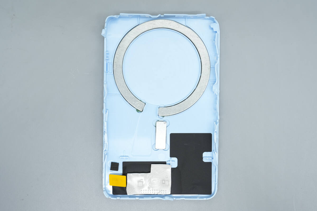
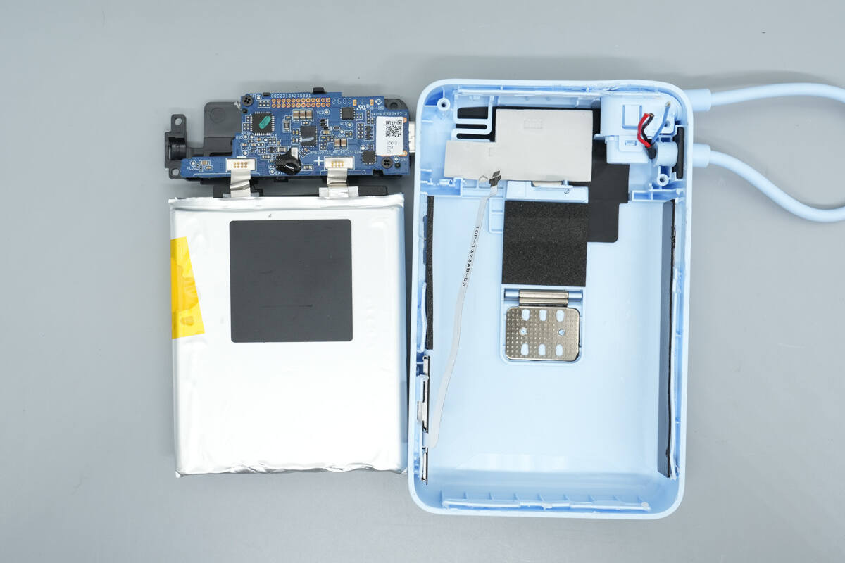
On the inner side of the cover, a circular magnetic ring is positioned at the top, while a large graphite thermal pad is attached at the bottom.
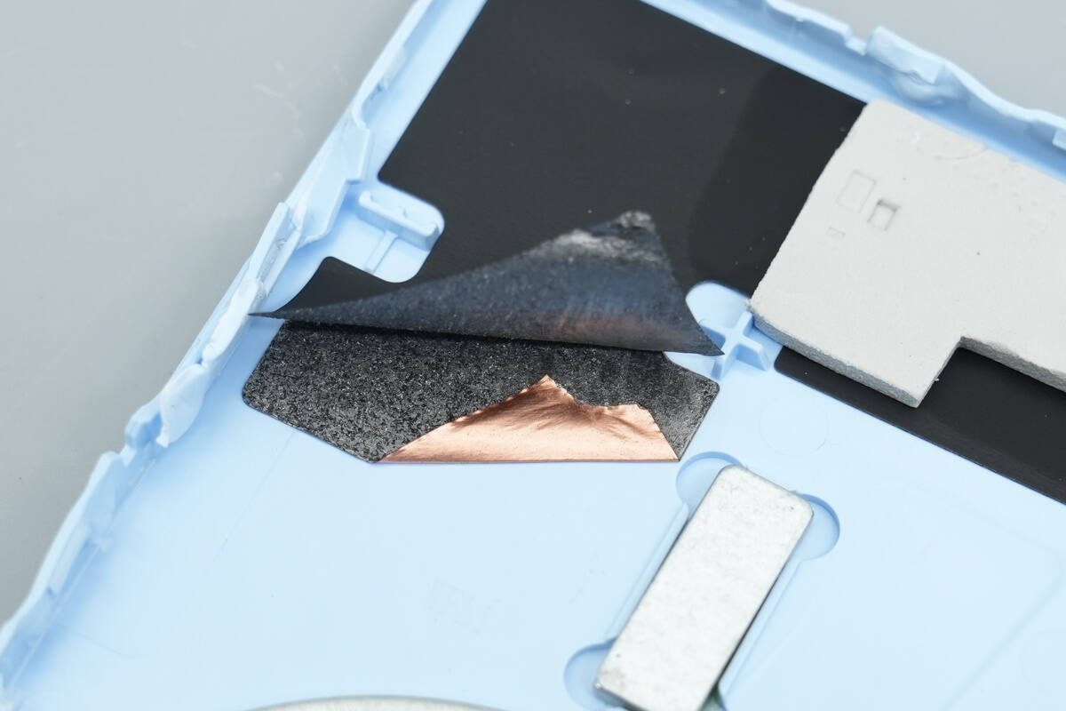
Peeling off the adhesive reveals the graphite thermal pad underneath.
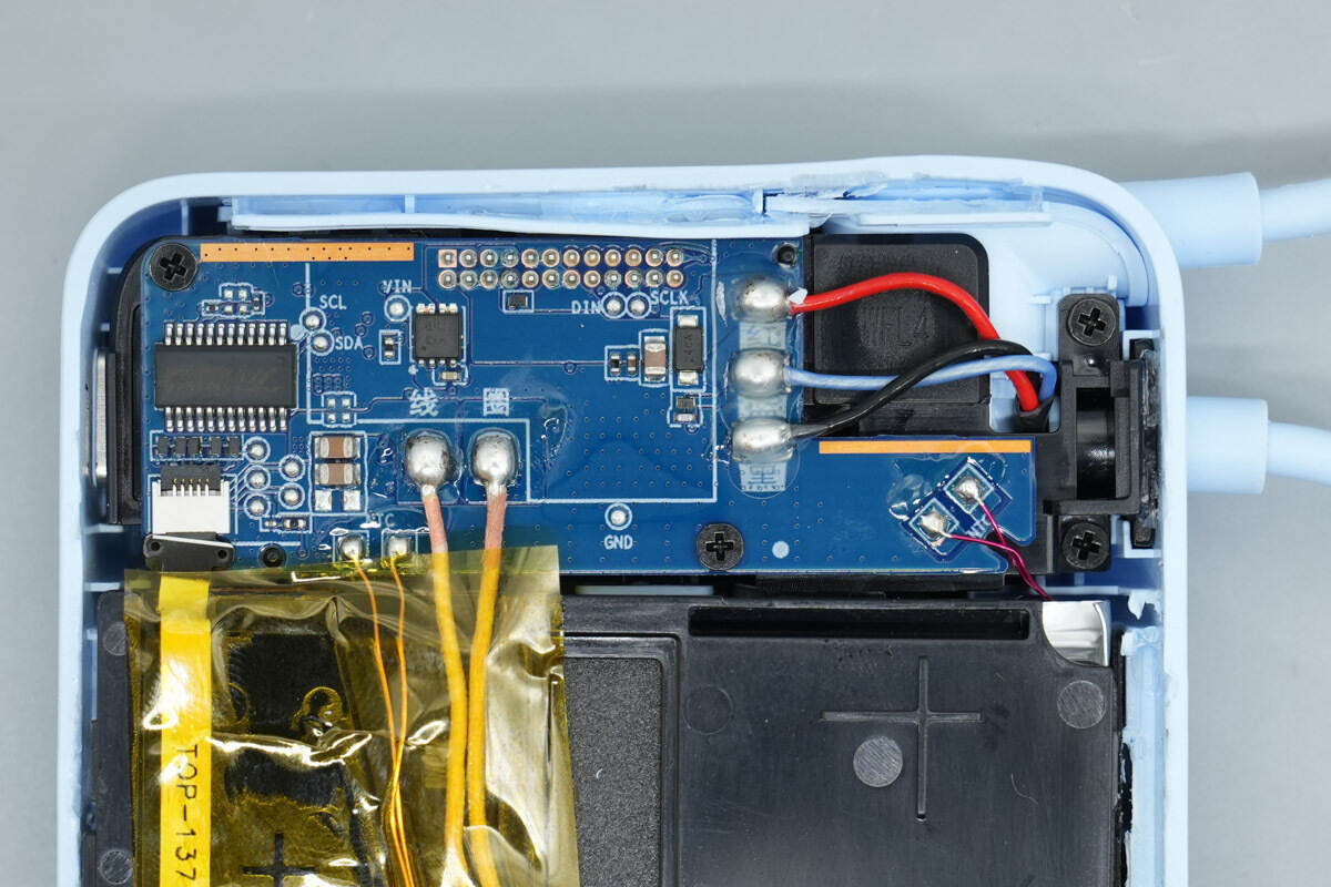
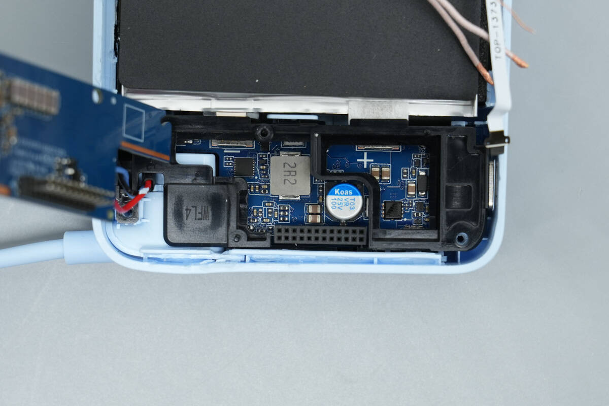
A close-up of the PCBA module.
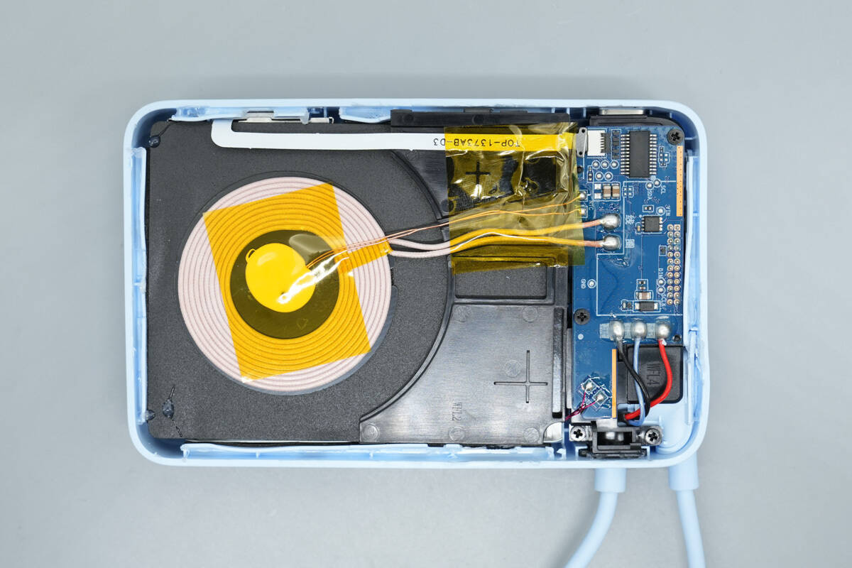
The internal layout of the device is compact and neatly organized.
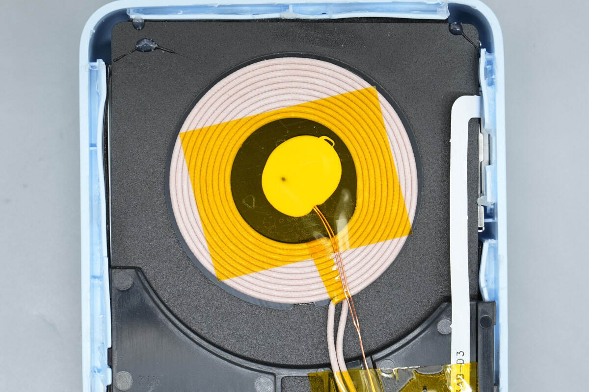
At the center of the charging coil, an NTC thermistor is installed and secured with high-temperature-resistant tape.
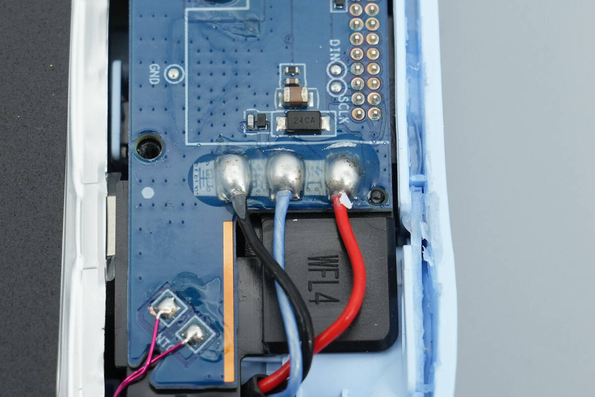
The positive and negative leads of the battery pack, as well as the NTC sensor wires, are all soldered, with solder joints that are smooth and well-formed.
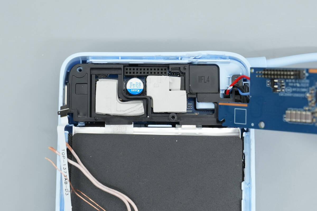
By unscrewing the screws and opening the PCB, it can be seen that the module consists of two stacked PCBs, with the lower one filled with thermal pads.
After removing the thermal pads, the bottom PCB becomes visible.
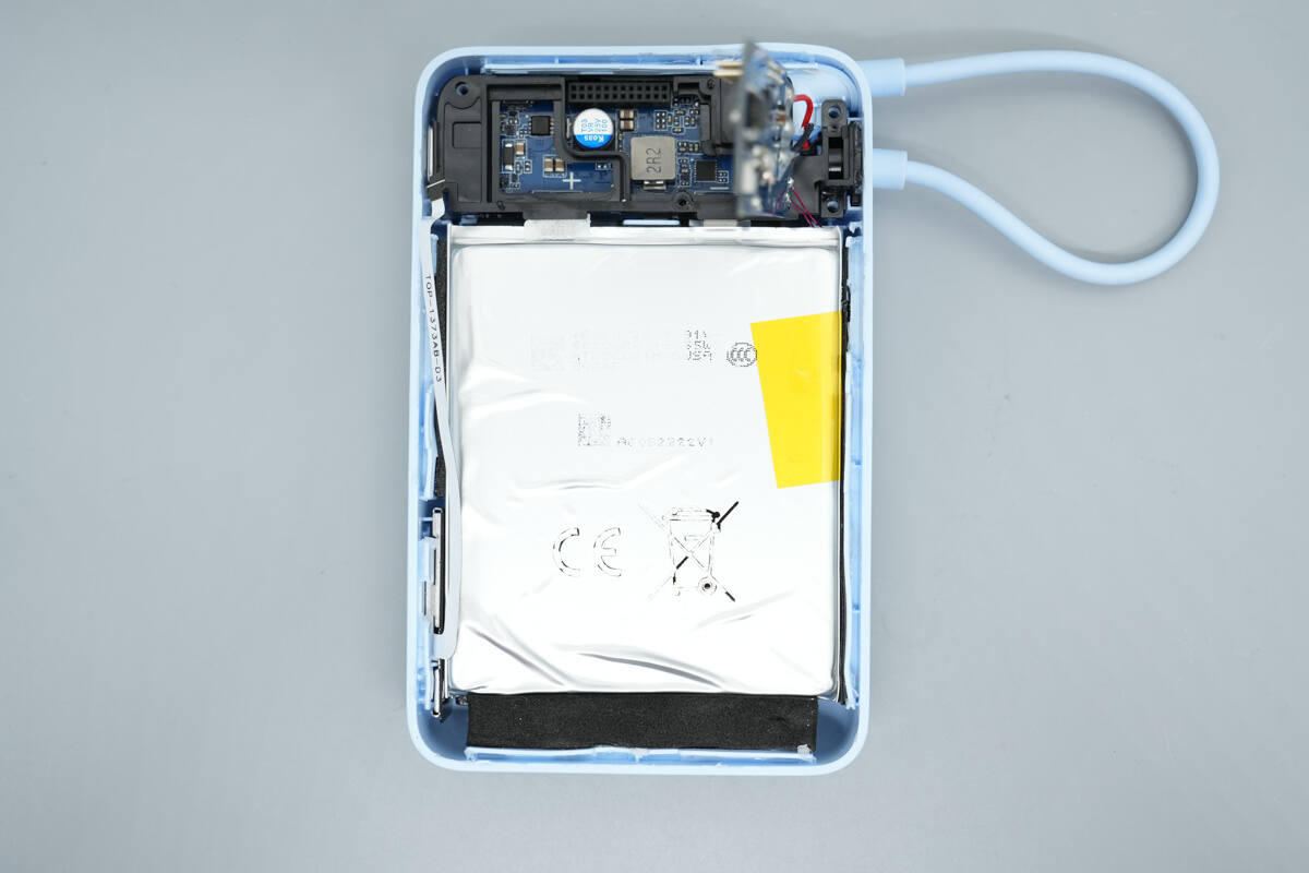
After removing the wireless charging module, the battery pack is exposed, with its surface wrapped in silver aluminum-plastic film.
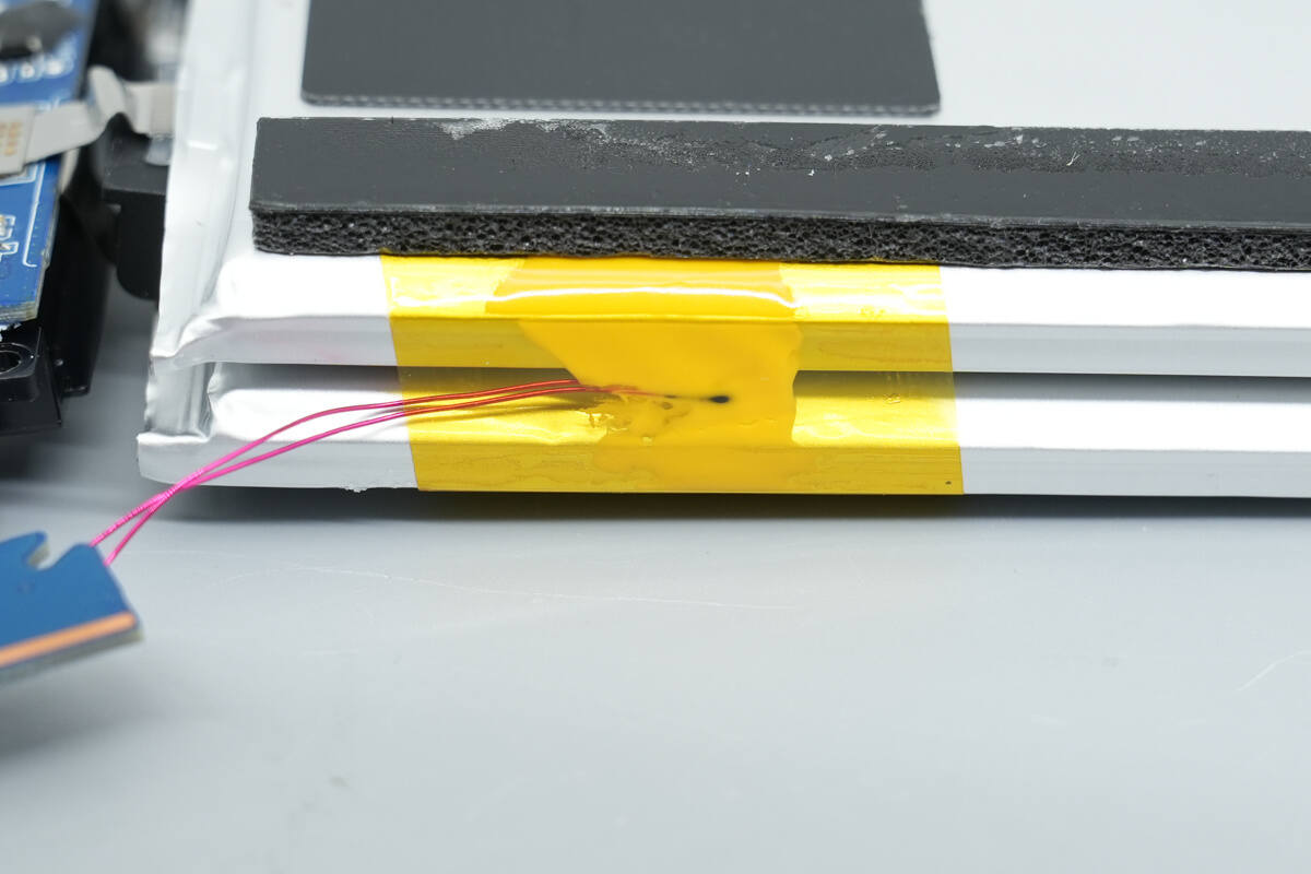
After removing the battery pack, an NTC thermistor can be seen on the side.
The battery tabs are connected to the mainboard using spot welding.
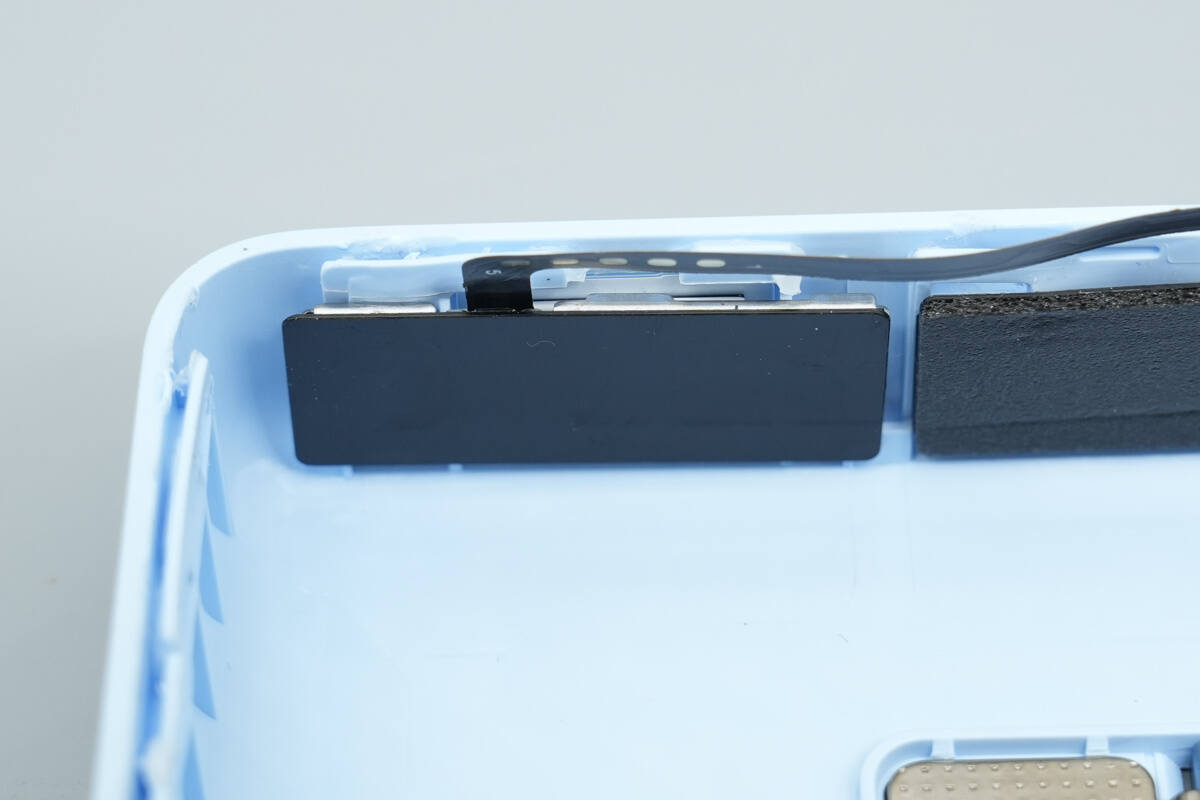
The inner side of the bottom case features cushioning foam and a flexible cable connecting to the display.
Close-up of the side digital tube display.
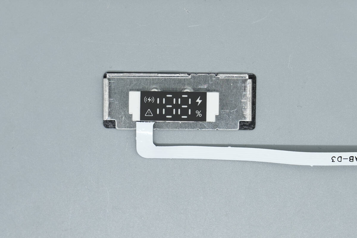
Close-up of the display.
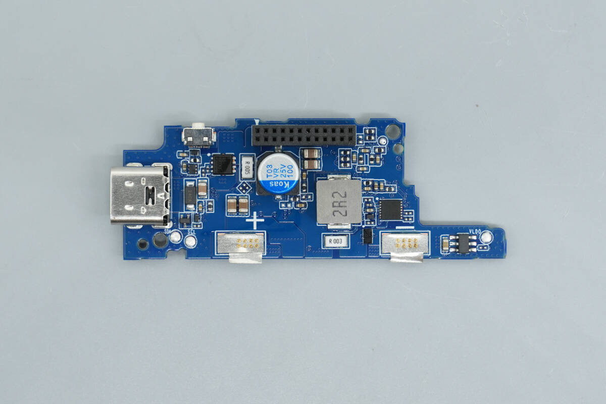
Overview of the component layout on the front side of the bottom PCB.
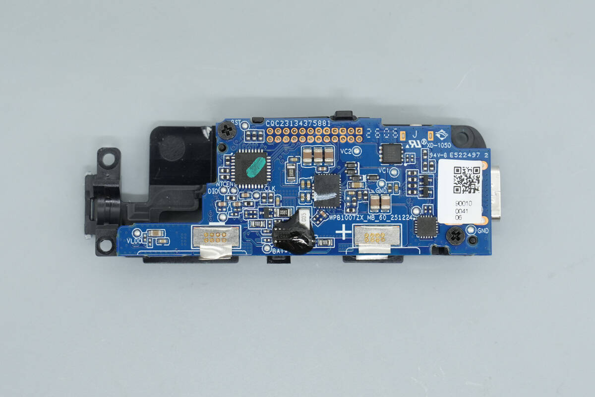
Close-up of the back side.
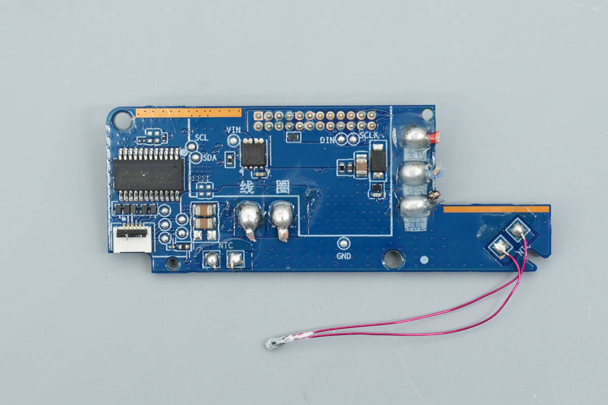
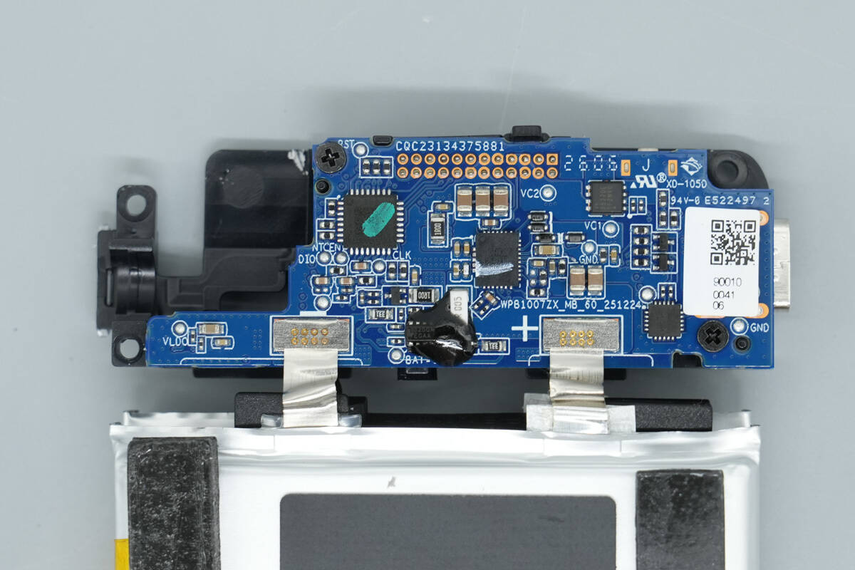
Overview of the component layout on the front side of the top PCB.
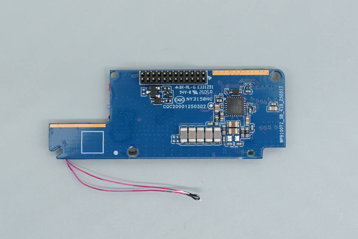
Overview of the component layout on the back side, featuring a 12-pin connector at the top for connection to the bottom PCB.
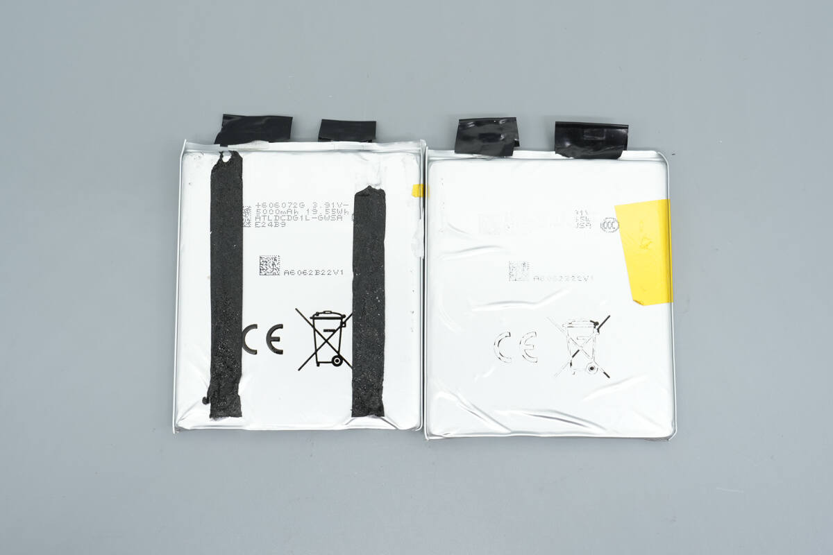
Separate the two battery cells.
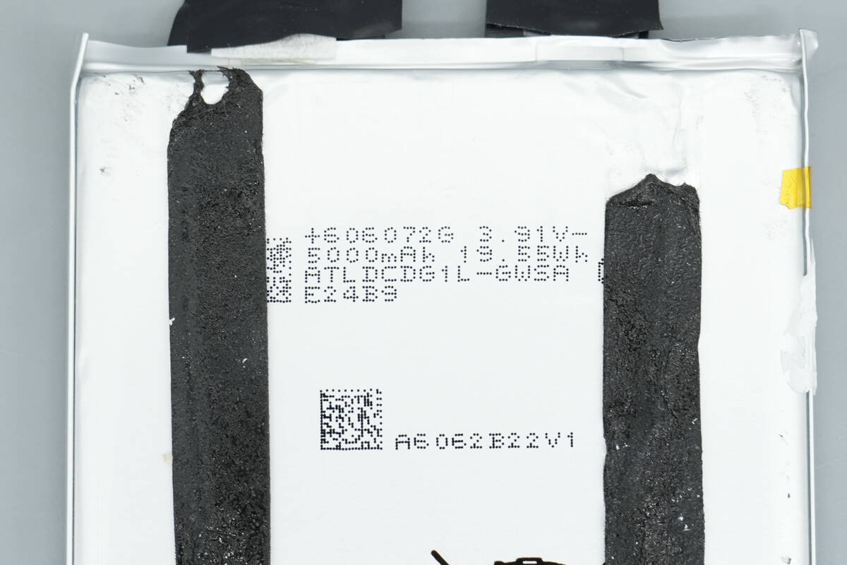
The battery cells are sourced from ATL, each with a capacity of 5000 mAh, a nominal voltage of 3.91 V, and an energy of 19.55 Wh. The two cells combined provide a total capacity of 10,000 mAh.

The MCU is from WCH, model CH32X035F8U6, used for overall device control, digital display driving, and compliance with the new national standard requirements for mobile power banks.
It comes in a TSSOP20 package and is an industrial-grade microcontroller based on the Qingke V4C core. The CH32X035 integrates USB and PD PHY, supporting both USB Host and USB Device functions, USB PD, and Type-C fast charging. It also features a programmable protocol I/O controller and provides a rich set of peripherals, including OPA operational amplifiers, CMP voltage comparators, USART serial ports, I2C, SPI, timers, a 12-bit ADC, and Touchkey functionality.
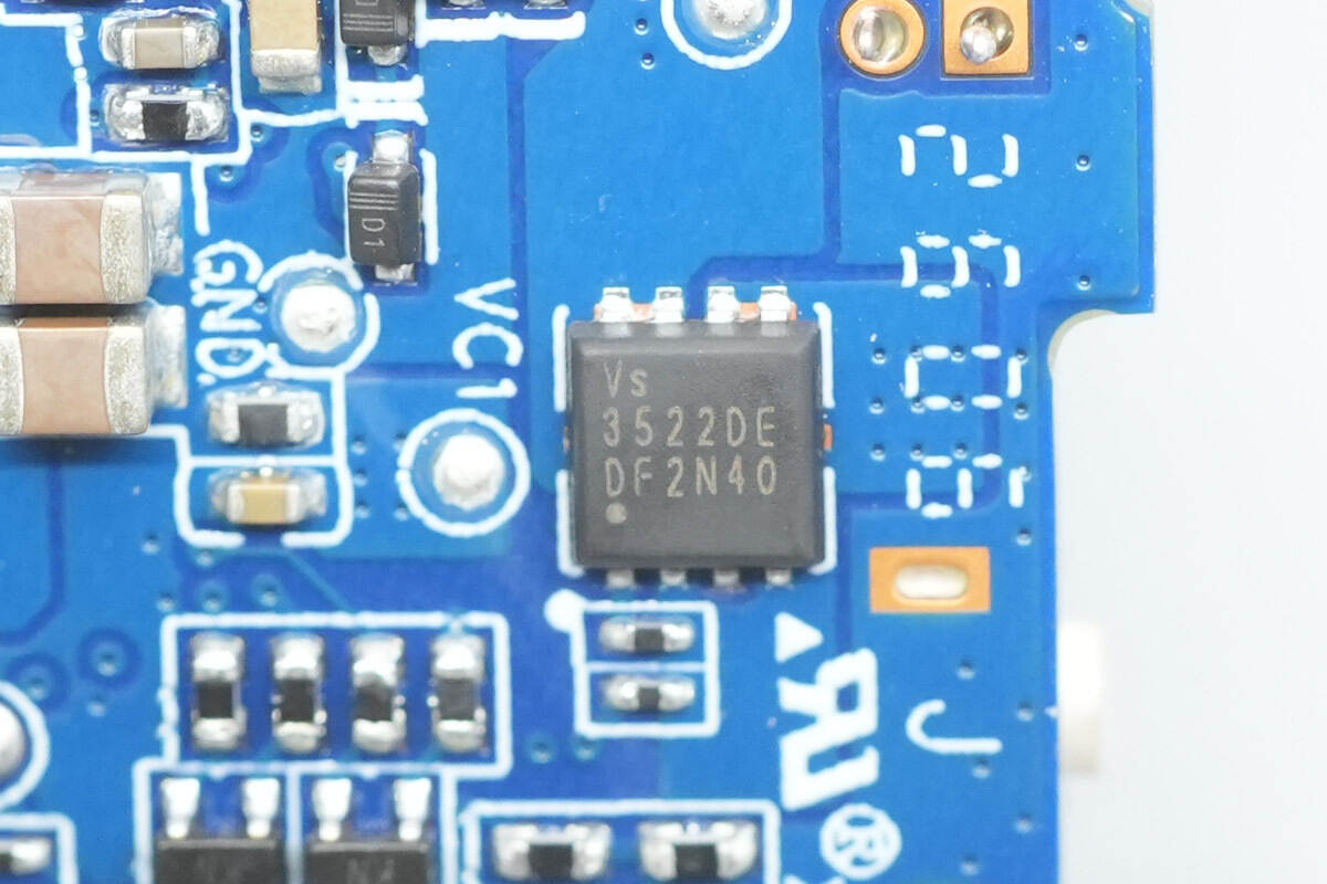
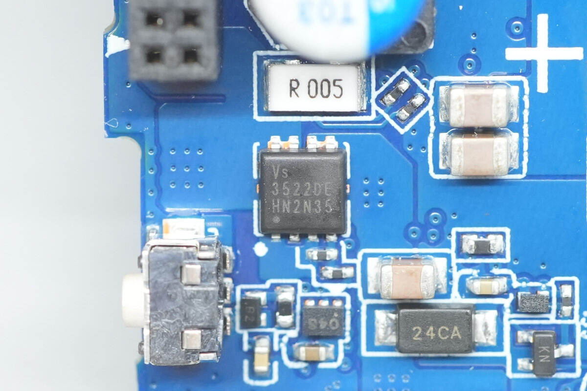
The VBUS MOSFET is from Vergiga, model VS3522DE, a dual PMOS with a voltage rating of –30 V and an on-resistance of 19 mΩ, housed in a PDFN3333 Dual package.
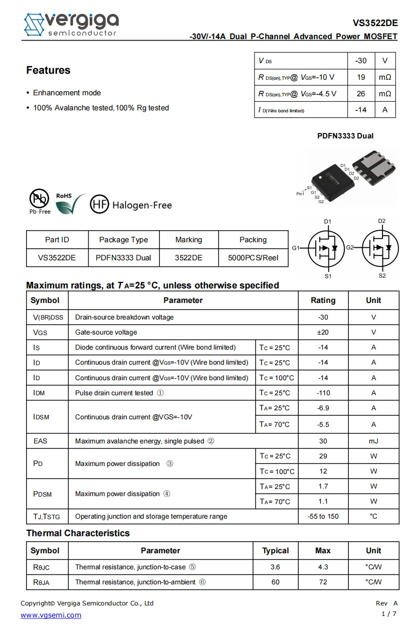
Here is the information about VS3522DE.
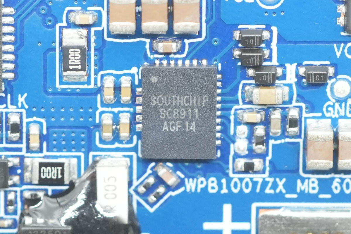
The synchronous buck-boost converter is from SouthChip, model SC8911. It supports buck, boost, and buck-boost modes during both forward charging and reverse discharging operations. The SC8911 manages charging for 2-cell lithium-ion and LiFePO₄ batteries, supporting trickle charge, pre-charge, constant current (CC) charge, constant voltage (CV) charge, and automatic termination.
In battery discharge mode, it provides a wide output range of 3.3–21 V. Through the I²C interface, users can easily configure charging and discharging modes and flexibly program parameters such as charging current, charging voltage, input voltage regulation, input current limit, OTG output voltage regulation, current limit, and other settings.
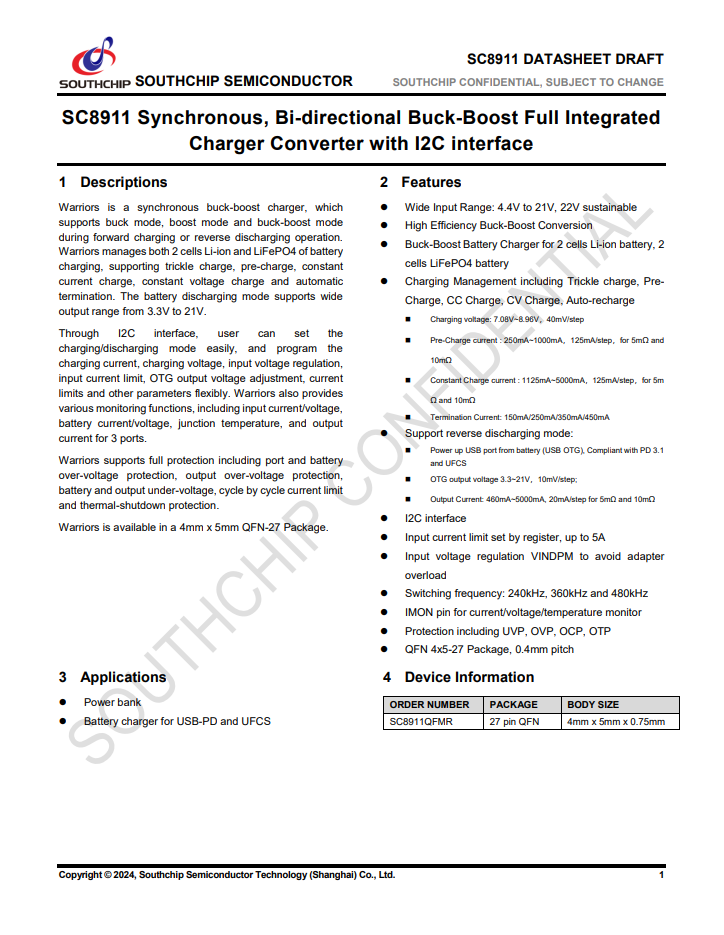
The SC8911 also provides comprehensive monitoring functions, including input current/voltage, battery current/voltage, junction temperature, and output current for three ports. It supports full protection features, including port and battery overvoltage protection, output overvoltage protection, battery and output undervoltage protection, cycle-by-cycle current limiting, and thermal shutdown. The SC8911 comes in a 4 mm × 5 mm QFN-27 package.
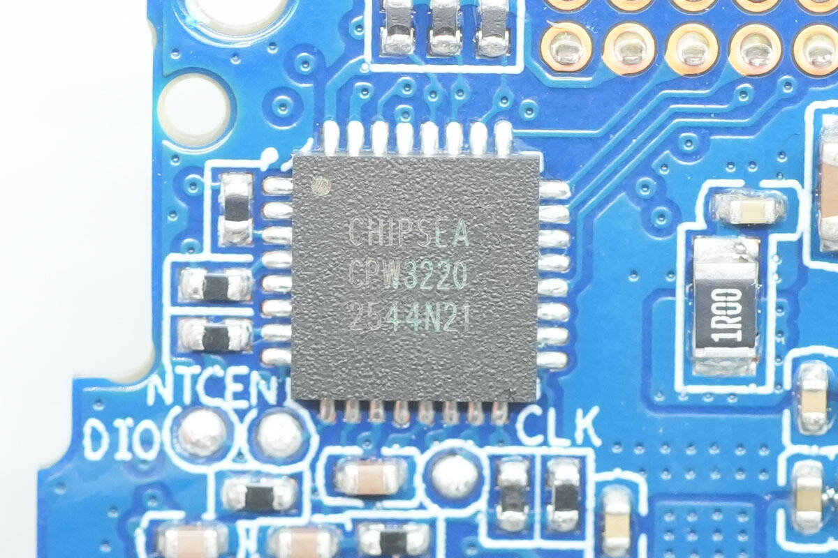
The protocol chip is from Chipsea, model CPW3220, a USB Type-C and USB PD controller designed for bidirectional battery applications. It integrates two independent Type-C CC channels and USB PD functionality, a load switch driver, and USB BC1.2 support.
The chip also incorporates multiple fast-charging protocols for smartphones, enhancing compatibility with end devices. It can be used in power banks, power tools, and similar applications, enabling a dual Type-C port solution with a single chip.
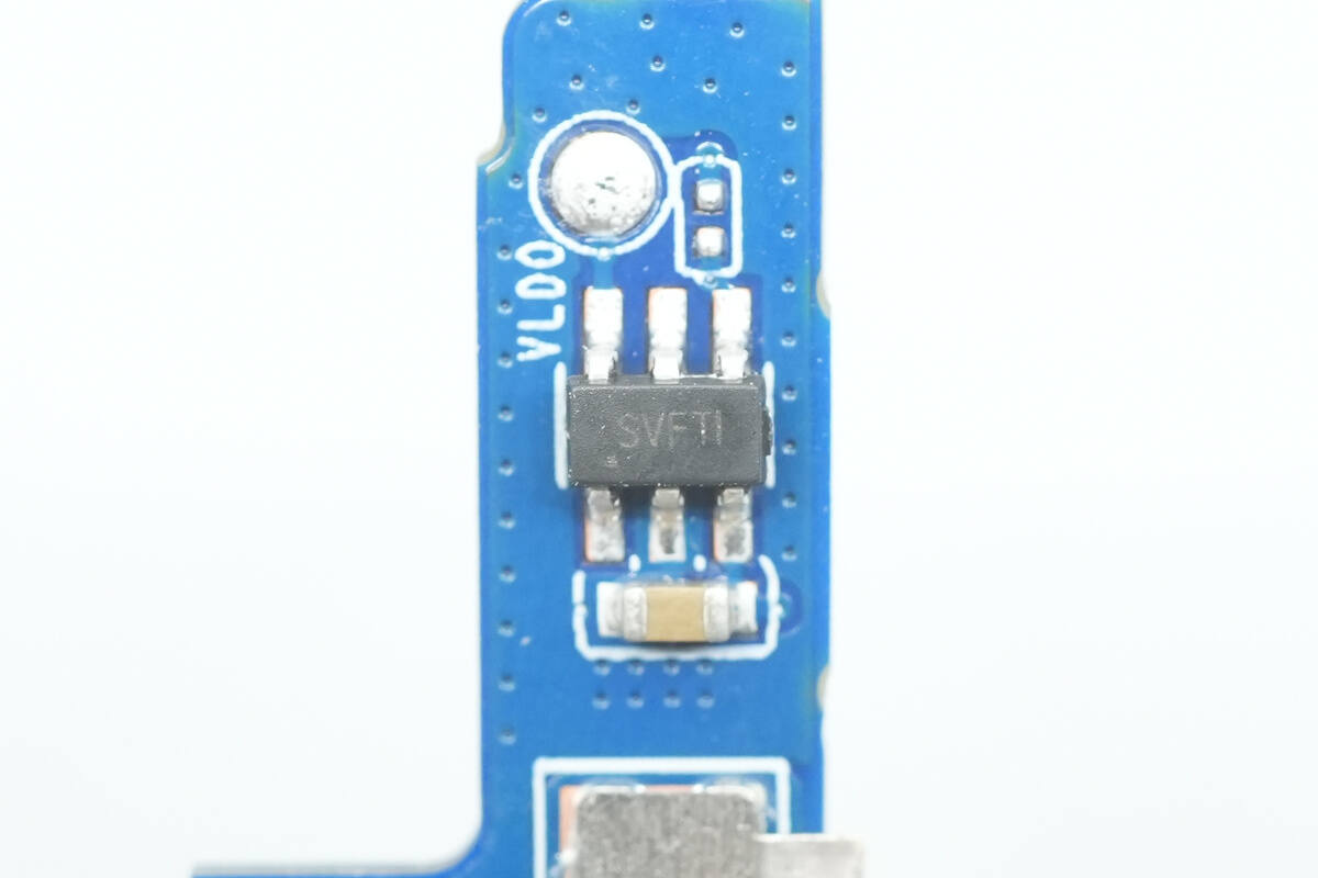
The LDO linear regulator, marked SVFTI, is from SGMICRO, model SGM2202, in an SOT23-6 package.
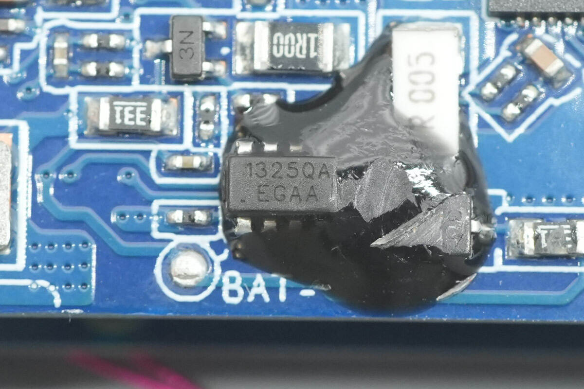
The battery protection chip is from iCM, model CM1325-QAK. It is a 2-cell rechargeable battery protection IC with a balancing function, housed in an SOT23-8 package.
Here is the information about CM1325-QAK.
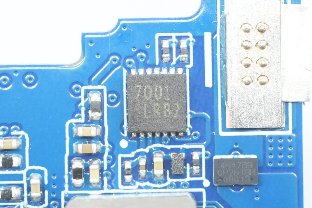
Close-up of a chip marked with 7001.
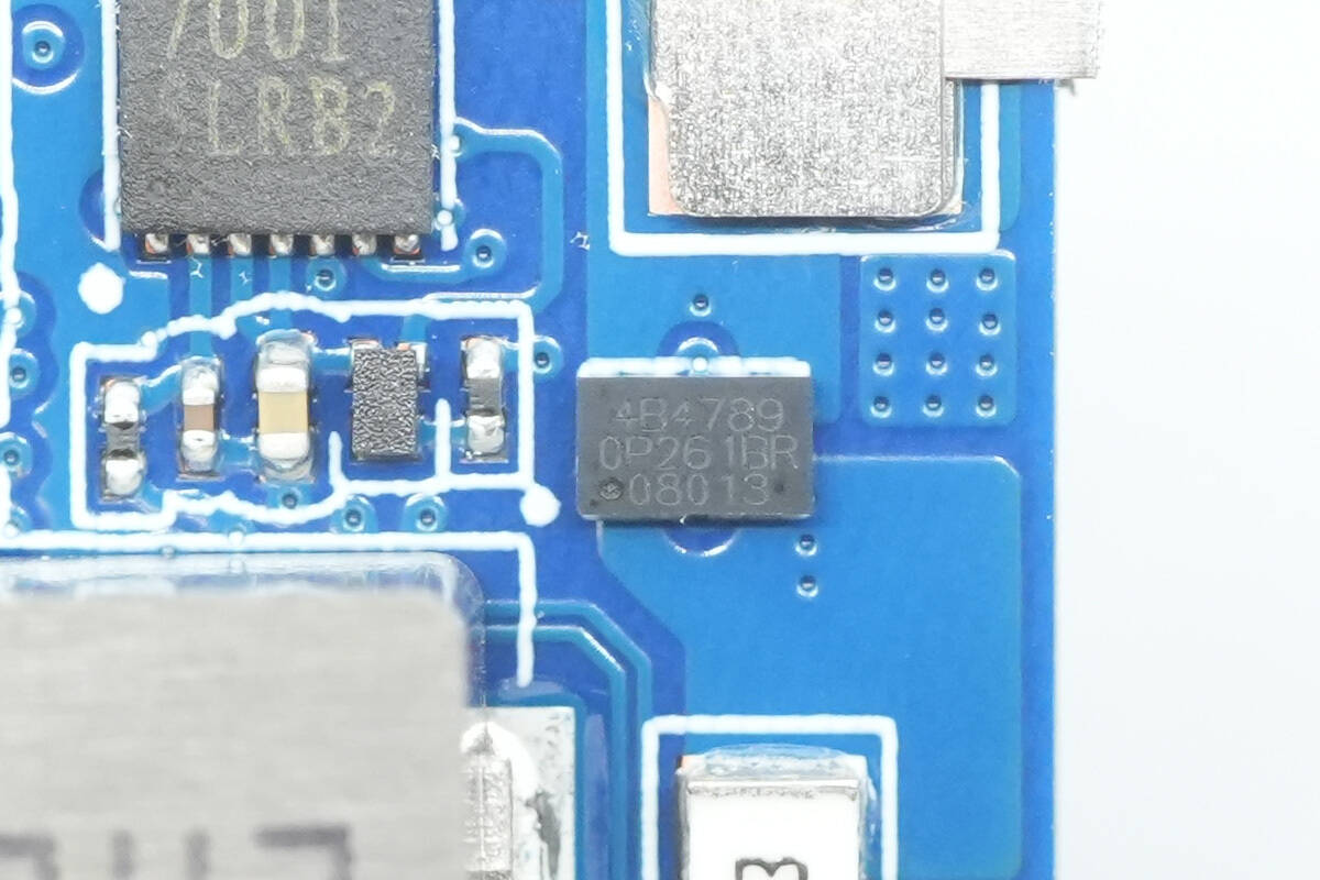
The battery protection MOSFET is marked with 4B4789.
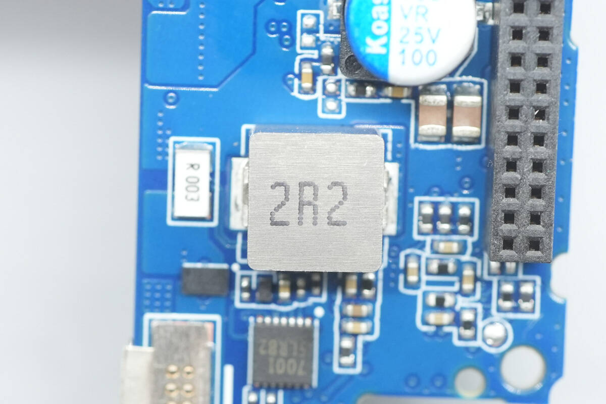
Close-up of a 2R2 alloy inductor.
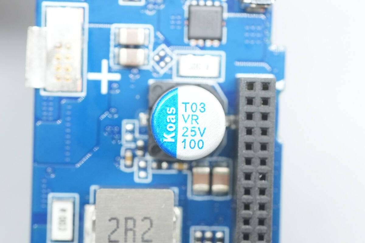
The solid capacitor is from Koshin, rated at 25 V, 100 μF.
Another VBUS MOSFET, also from Vergiga, model VS3522DE.
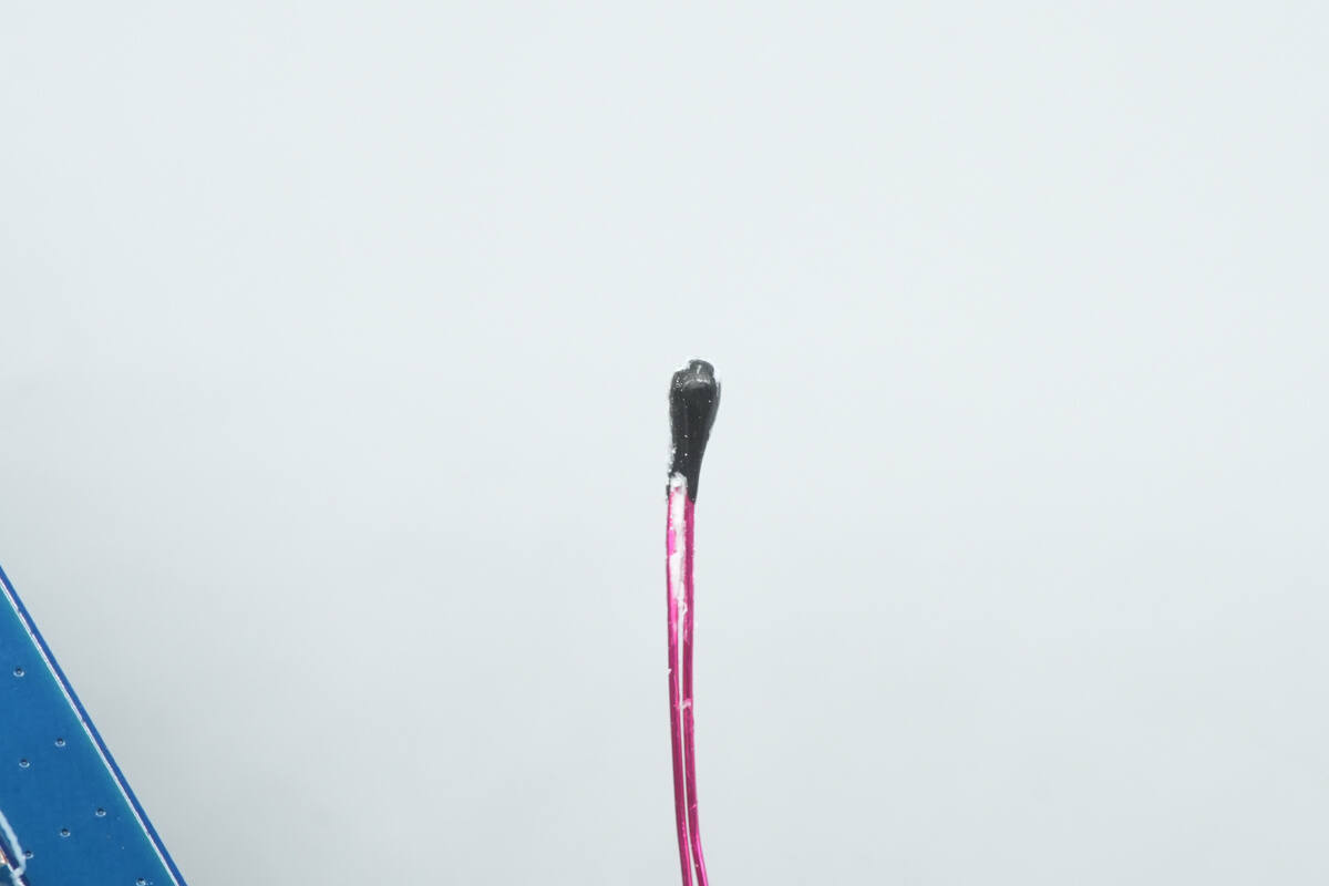
Close-up of the thermistor.
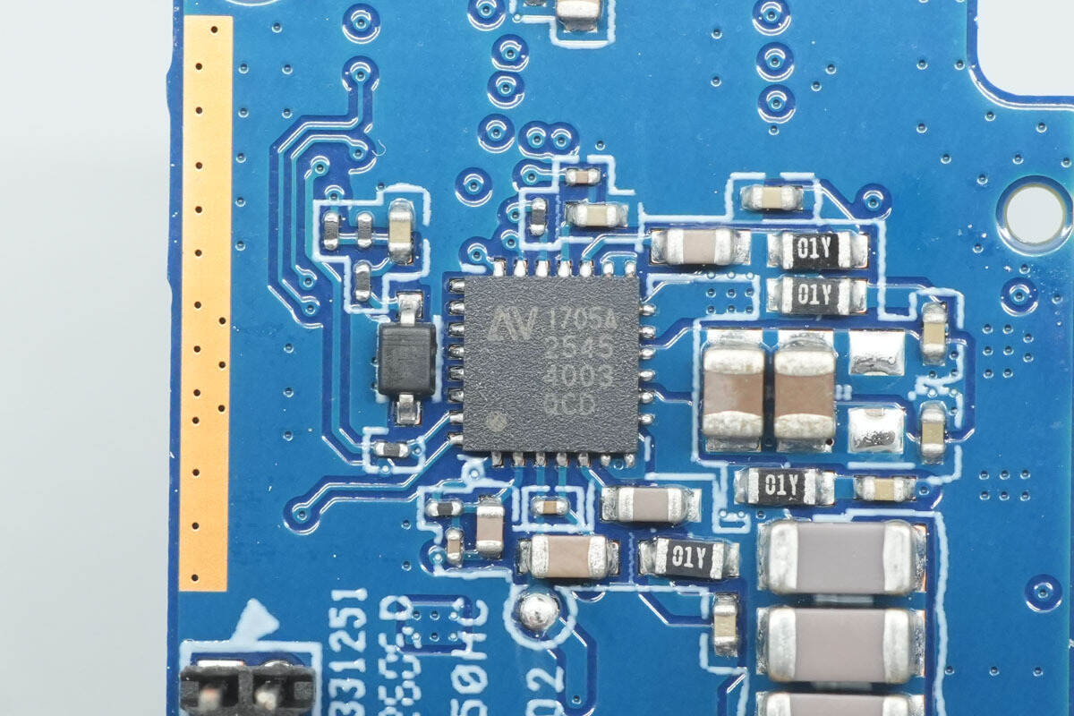
The wireless charging master control chip is from NuVolta, model NU1705A, featuring a full-bridge power stage architecture compatible with a wide frequency range and a 32-bit MCU core. The power system integrates all key functional modules, including high-efficiency power MOSFETs, low-EMI FET drivers, bootstrap circuitry, integrated 4.8 V/1.8 V LDO regulators, and lossless current-sensing technology.
Its patented current-sensing circuitry provides precise current readings for foreign object detection, power measurement, in-band communication, Q-factor detection, and digital demodulation. The chip also features multiple protection mechanisms, including input undervoltage lockout, overvoltage protection, overcurrent protection, the proprietary JuggleProtection dynamic circuit, and thermal shutdown, all of which significantly enhance the reliability of the overall system solution. Packaged in a 4 mm × 4 mm QFN.
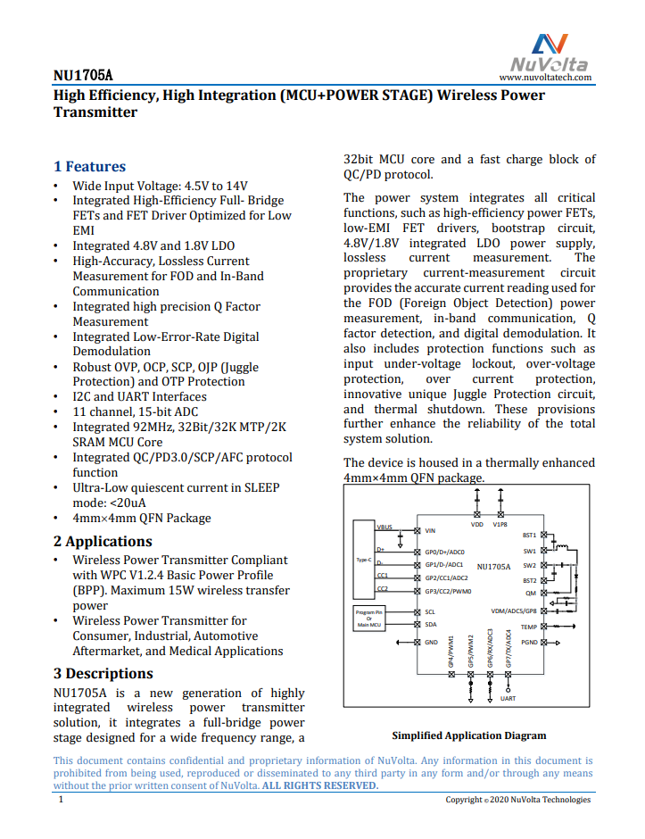
Five capacitors for wireless charging resonance.
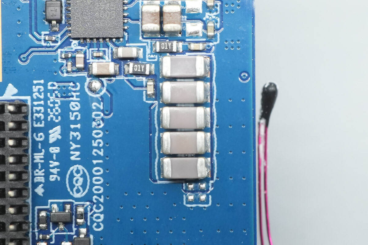
A MOSFET marked 03111 is used for switching resonance capacitors in wireless charging.
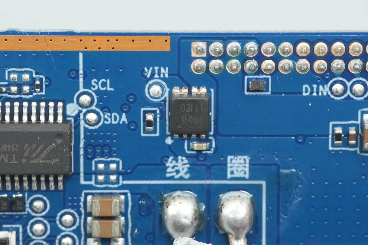
The display driver chip is from TM, model TM1646.

Well, those are all components of the Xiaomi 10000mAh Magnetic Power Bank.
Summary of ChargerLAB
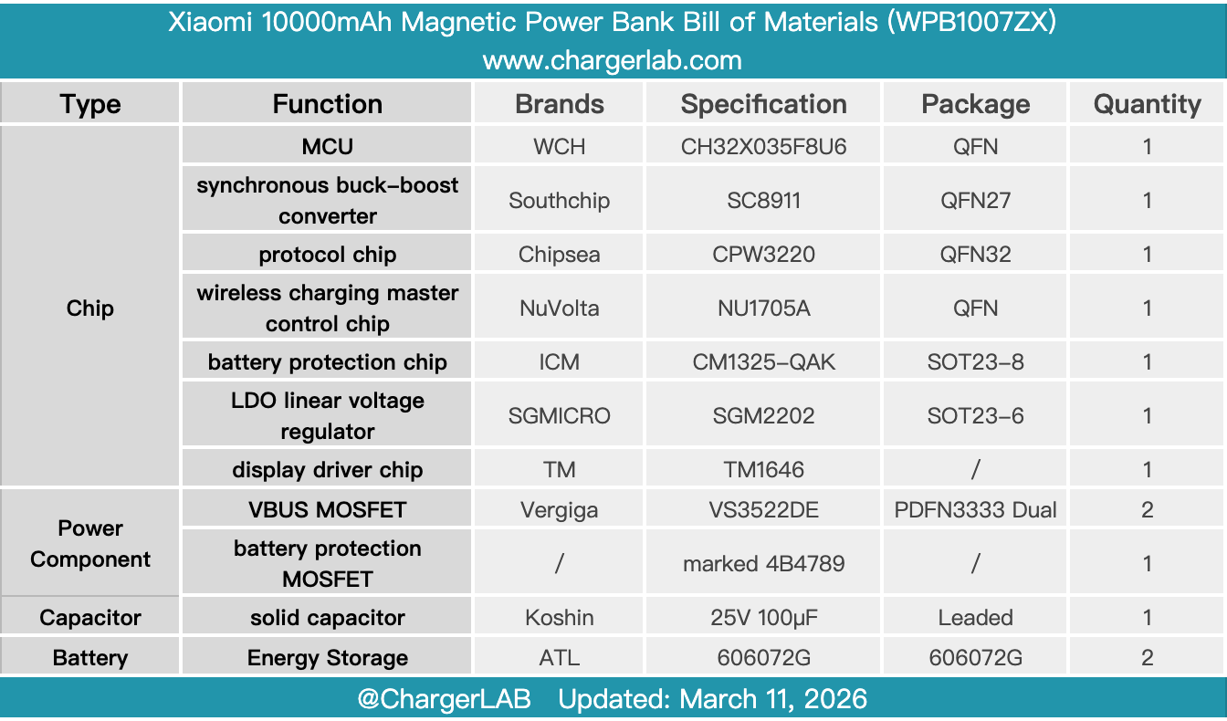
Here is the component list of the Xiaomi 10000mAh Magnetic Power Bank for your convenience.
The enclosure is made of skin-friendly material with a delicate texture. It integrates magnetic wireless charging, a foldable stand, and a built-in cable, addressing pain points across various usage scenarios.
After taking it apart, we found that it contains ATL battery cells with a total capacity of 10,000 mAh, and utilizes a SouthChip synchronous buck-boost controller, a Chipsea protocol chip, and a NuVolta wireless charging master control chip, paired with a WCH MCU. Battery health and related information can be quickly checked via the official Xiaomi website. Internally, it is equipped with an NTC thermistor and large-area heat-dissipating stickers to ensure stability during extended use.
Related Articles:
1. Teardown of MENNEKES EV Charging Cable (35305220027)
2. Teardown of Samsung 5000mAh Qi2 Magnetic Wireless Power Bank (EB-U2500)
3. Teardown of Huawei P30