Introduction
The RayNeo Magic Box 2 is a multifunctional device that supports video playback, screen casting, and NAS connections. It features FlyTouch gesture control for easier use. It can serve as a casting device, supporting ultra-high-definition audio and video output, and is compatible with various wireless protocols.
Inside, it is powered by the Amlogic S905X5M processor, with 3GB of RAM and 32GB of storage. It also supports up to 2TB of expandable storage via a TF card. The device is compatible with Android apps and allows installation of mainstream video apps. One side of the unit is equipped with a large touch-sensitive panel, enabling smooth and efficient operation. This teardown will examine its internal design and components.
Product Appearance
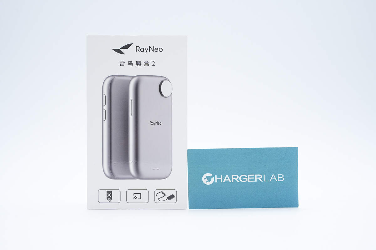
The packaging box features the RayNeo logo along with an image of the product.
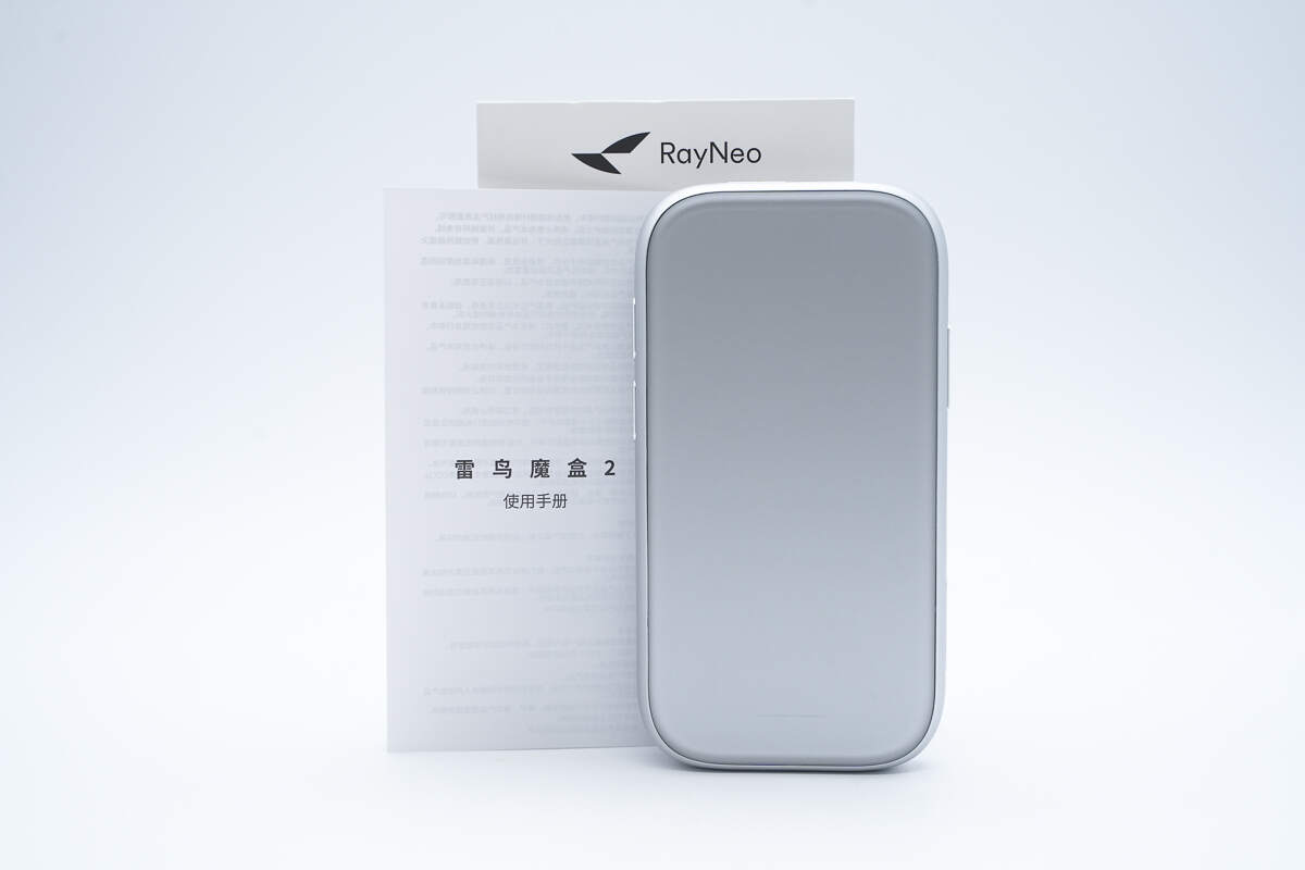
The package includes the Magic Box 2 and some documents.
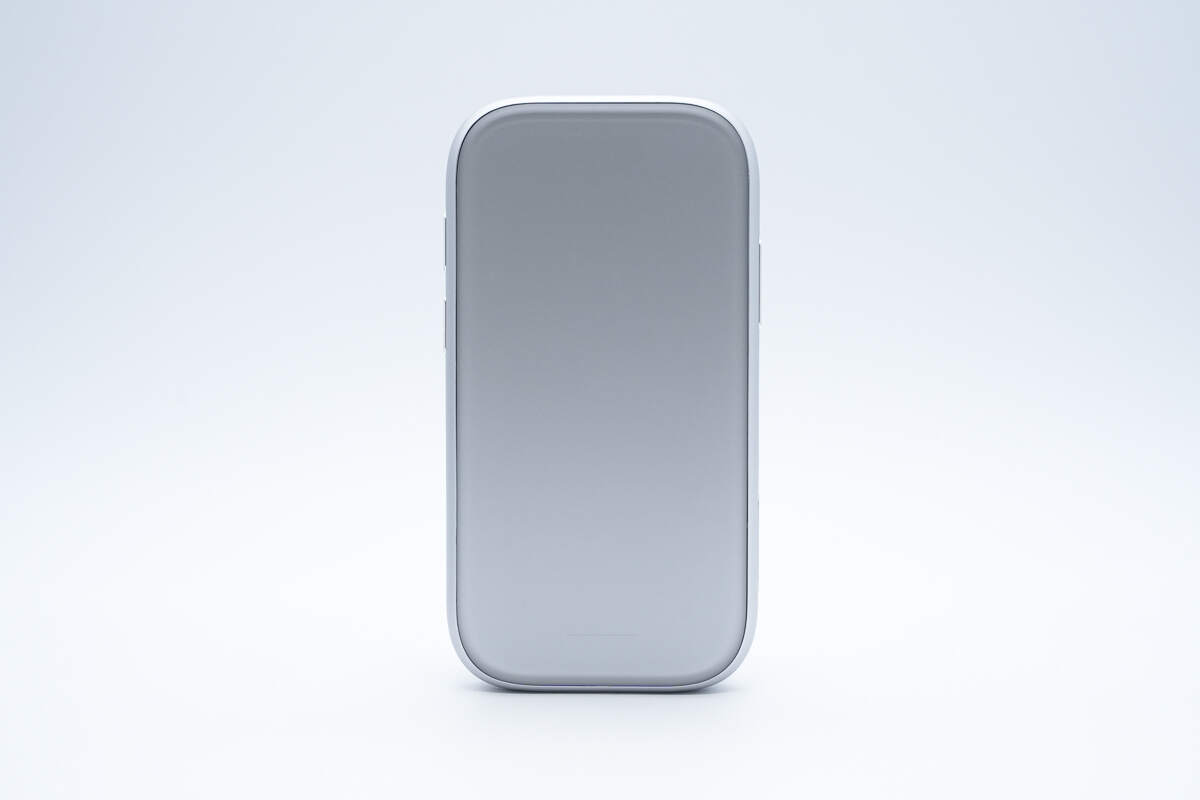
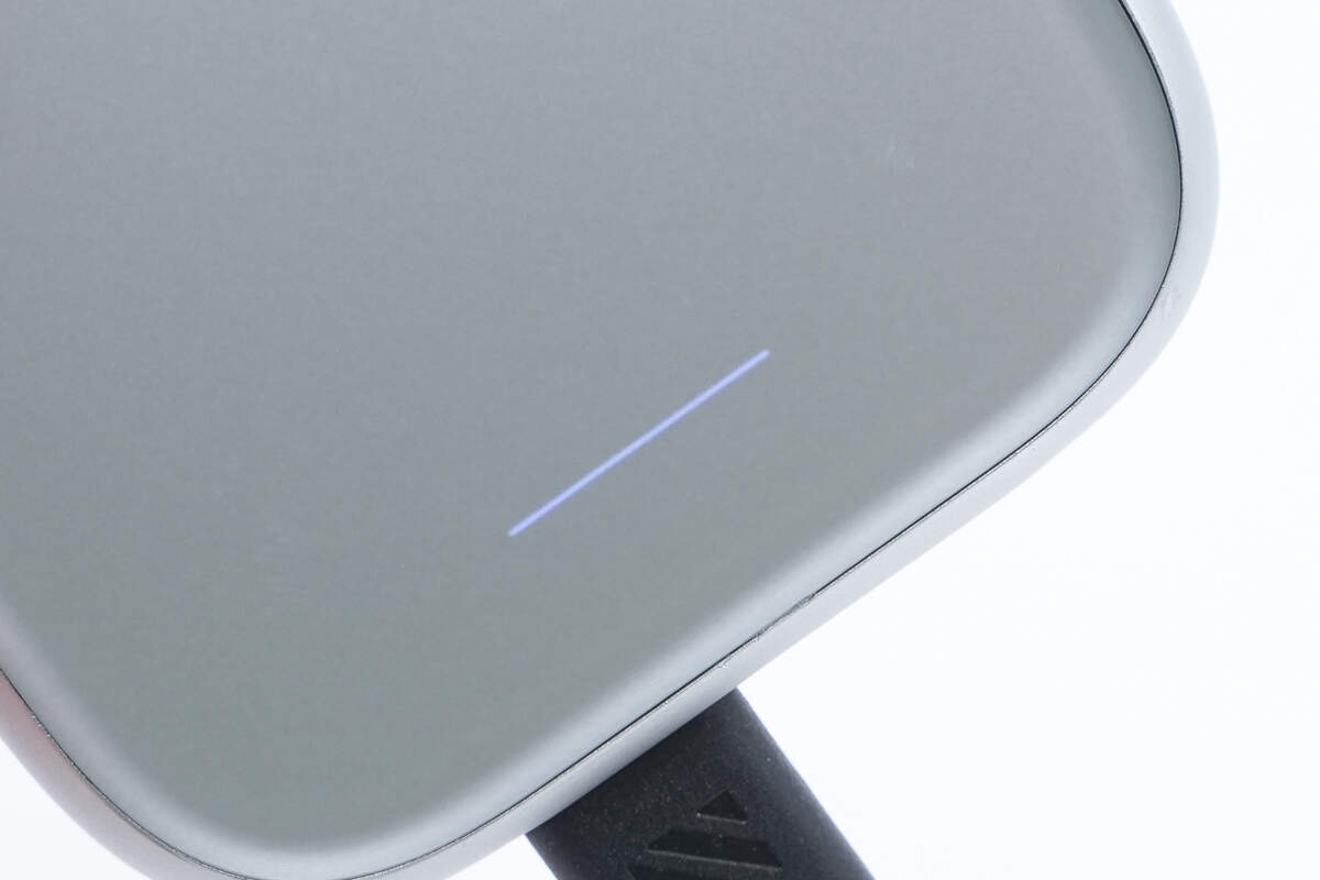
The front of the RayNeo Magic Box 2 features a touch panel.
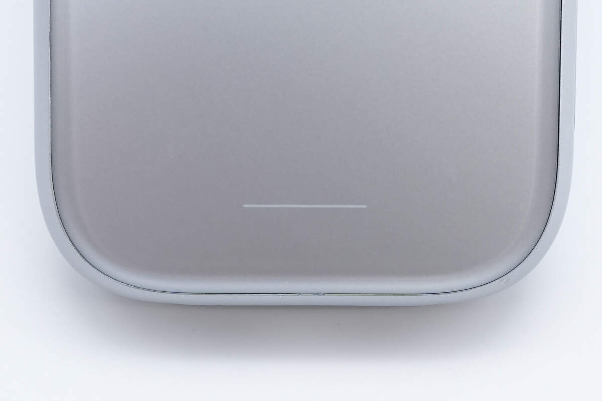
At the bottom of the panel, there is a linear status indicator light.
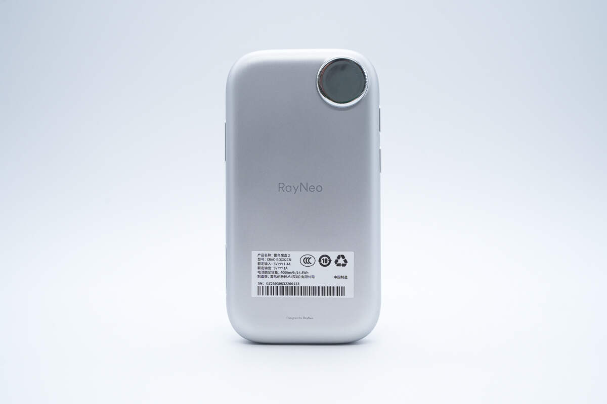
The back features a circular mirror-like decorative element.
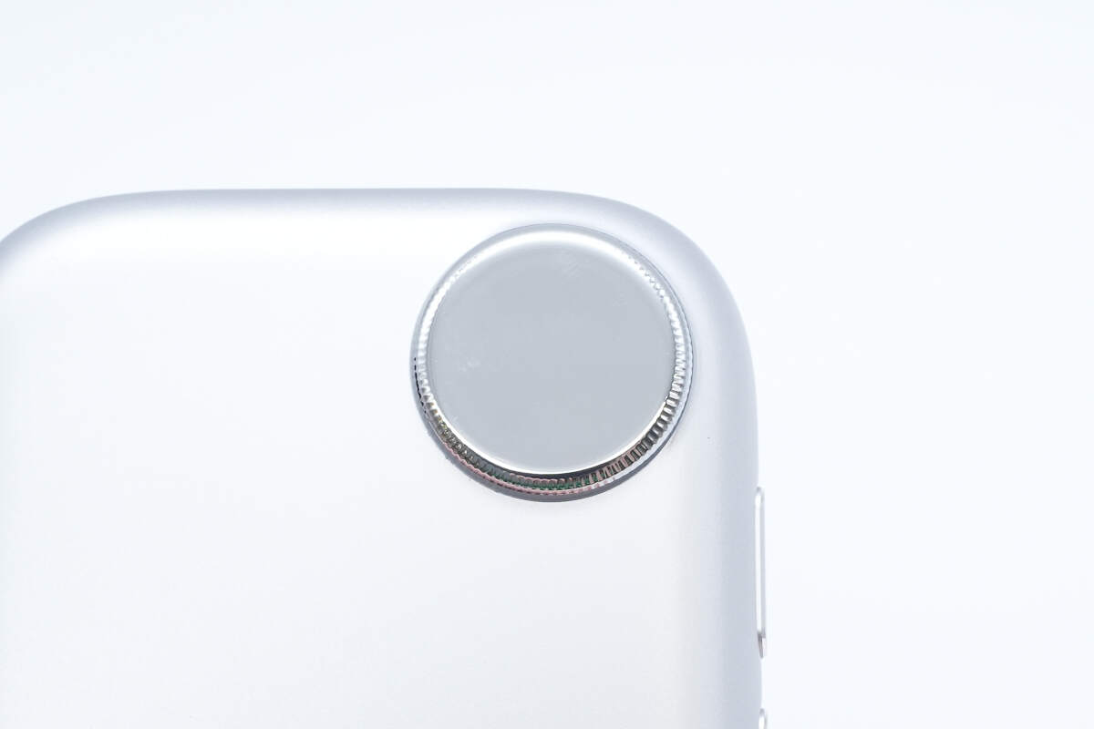
Close-up of the circular decorative element on the back.
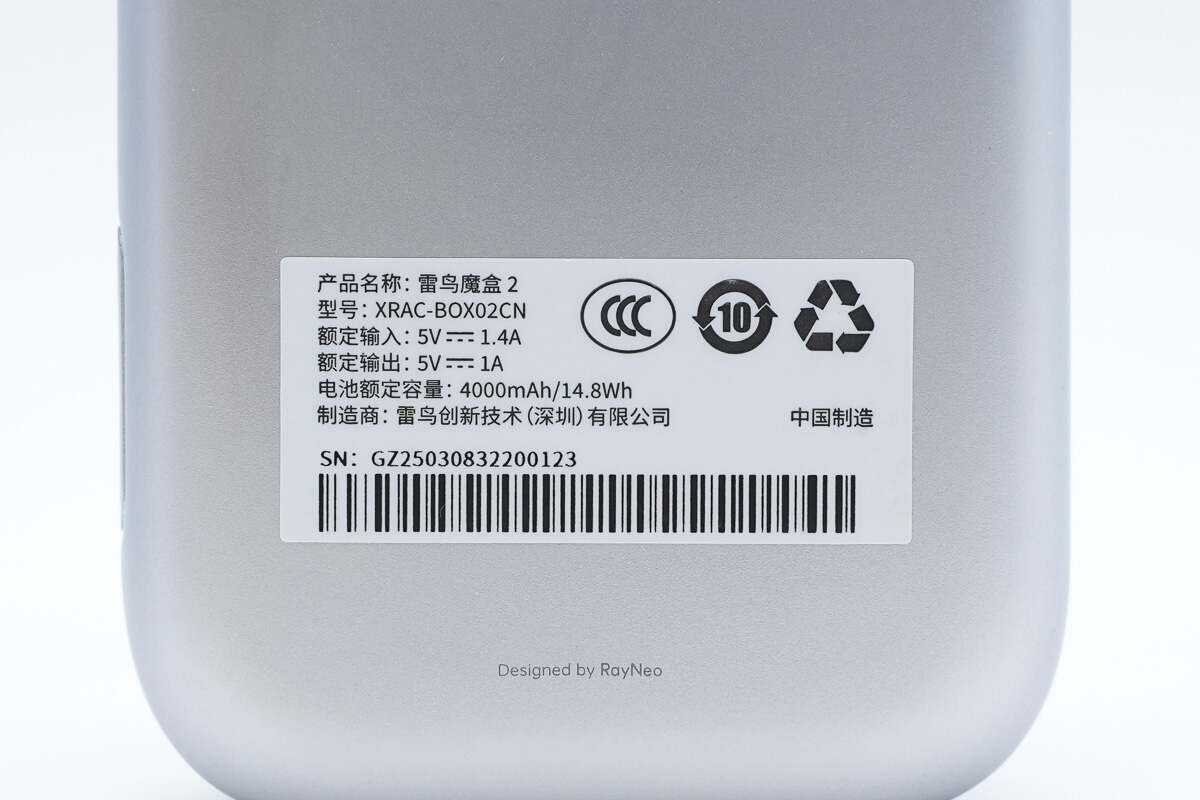
Model: XRAC-BOX02CN
Rated Input: 5V 1.4A
Rated Output: 5V 1A
Battery Capacity: 4000mAh / 14.8Wh
Manufacturer: RayNeo Innovation Technology (Shenzhen) Co., Ltd.
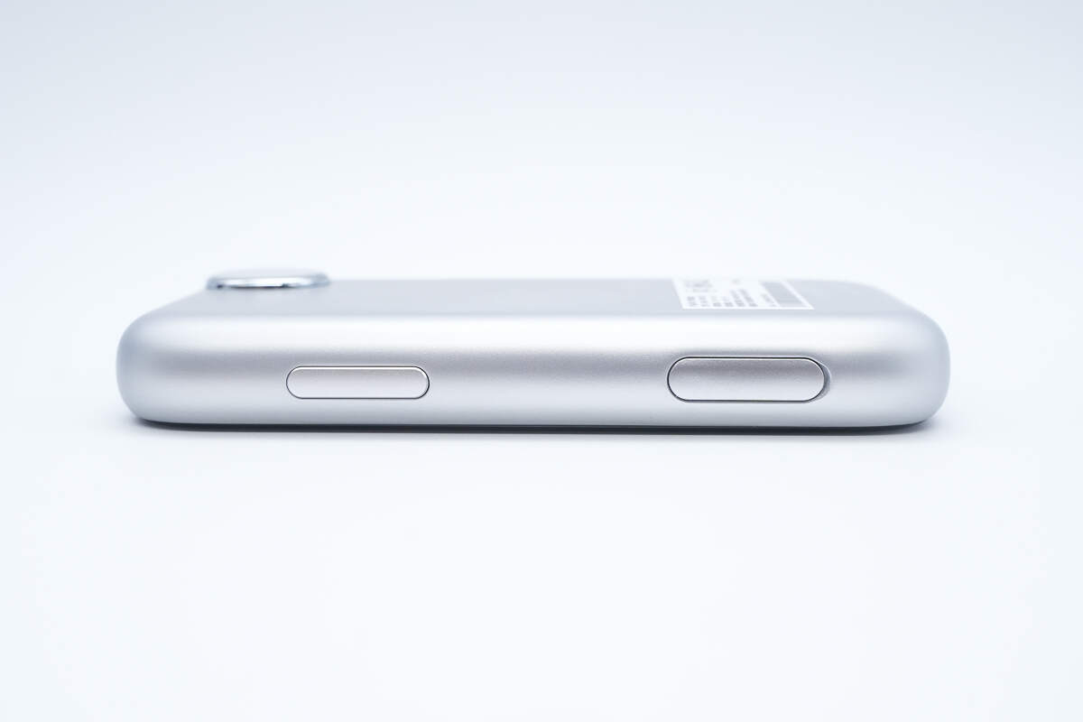
The top features a power button and an indicator light.

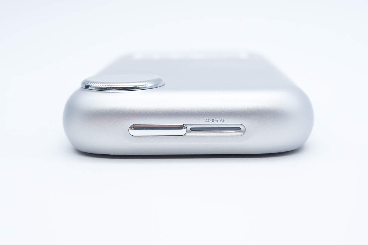
The side is equipped with volume up and down buttons.
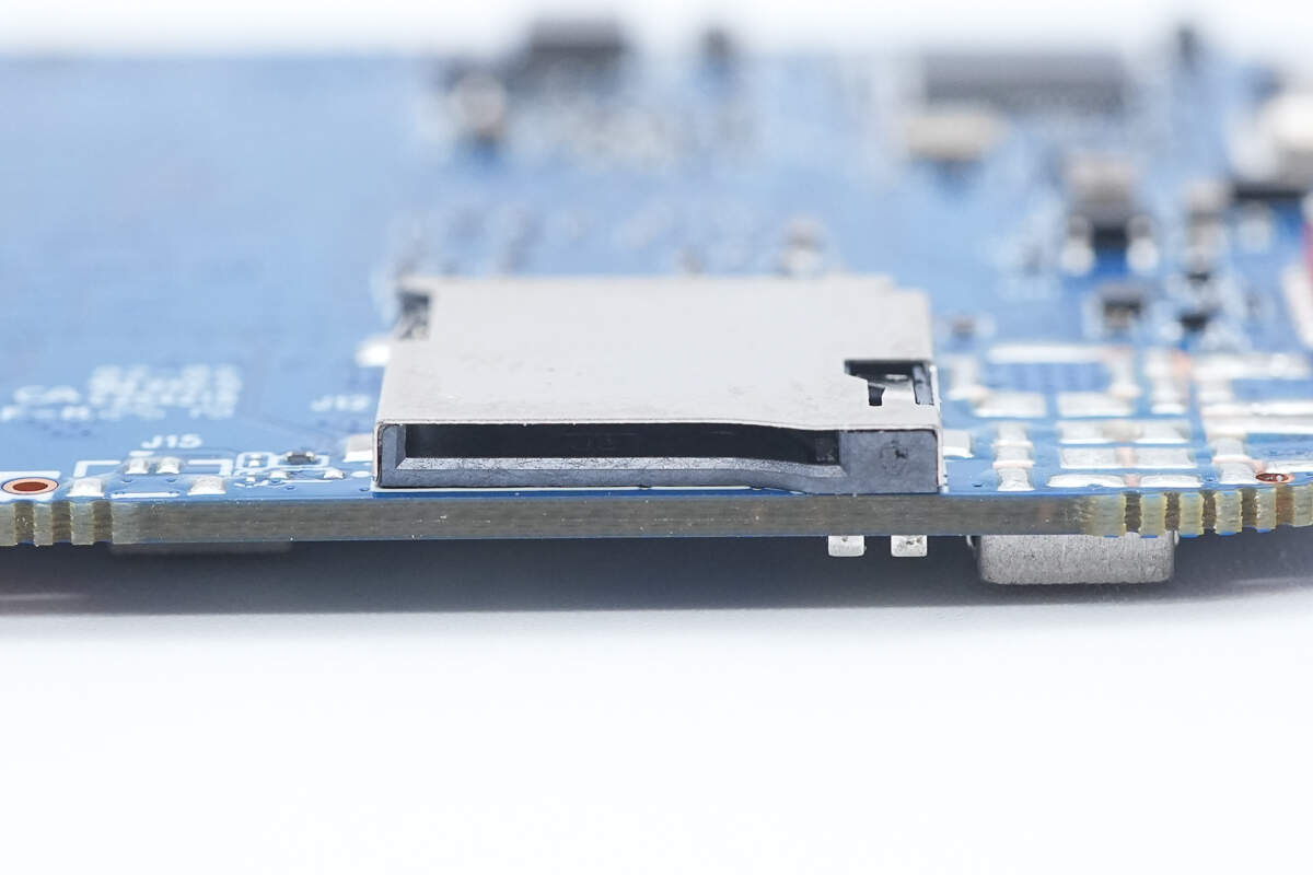
This side features a shortcut button and a Micro SD card slot.
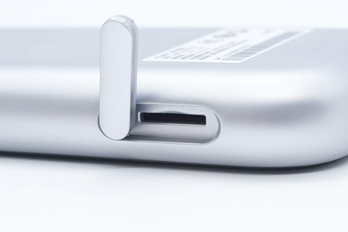
The Micro SD card slot is equipped with a cover.
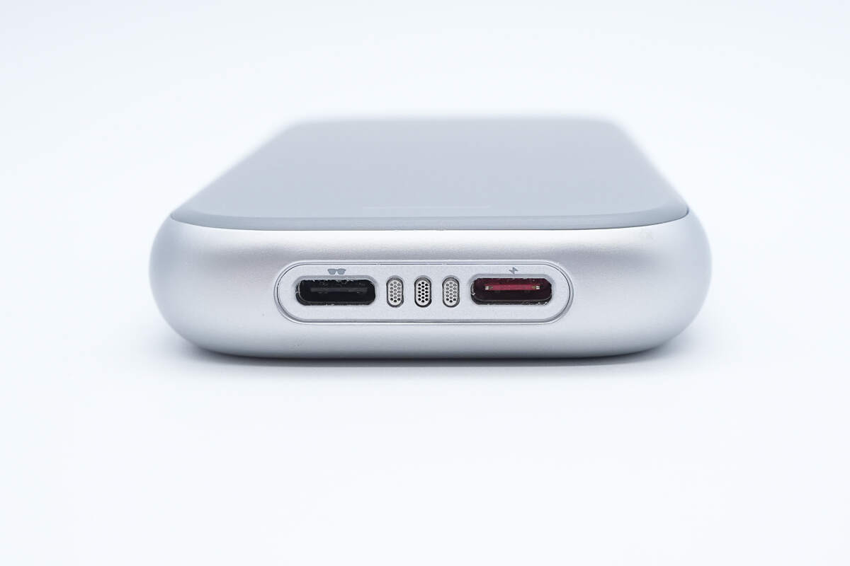
The bottom has a charging port and a glasses connector, with icons beside each port for identification.
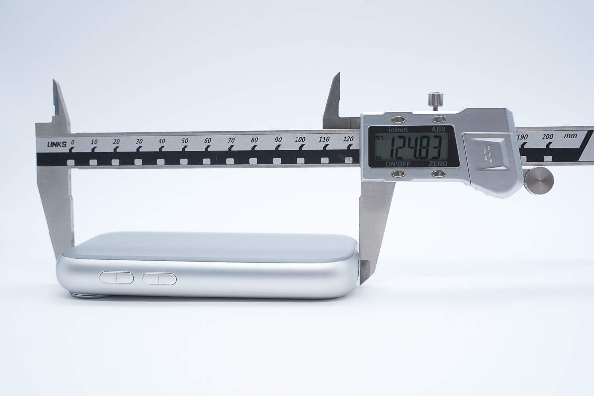
The length is about 125 mm (4.92 inches).
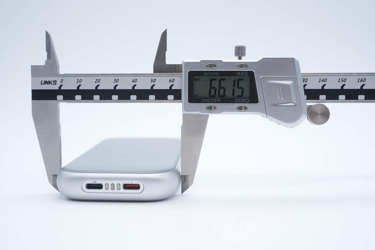
The width is about 66 mm (2.6 inches).
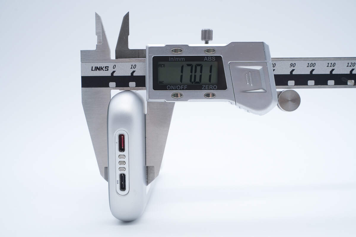
The thickness is about 17 mm (0.67 inches).
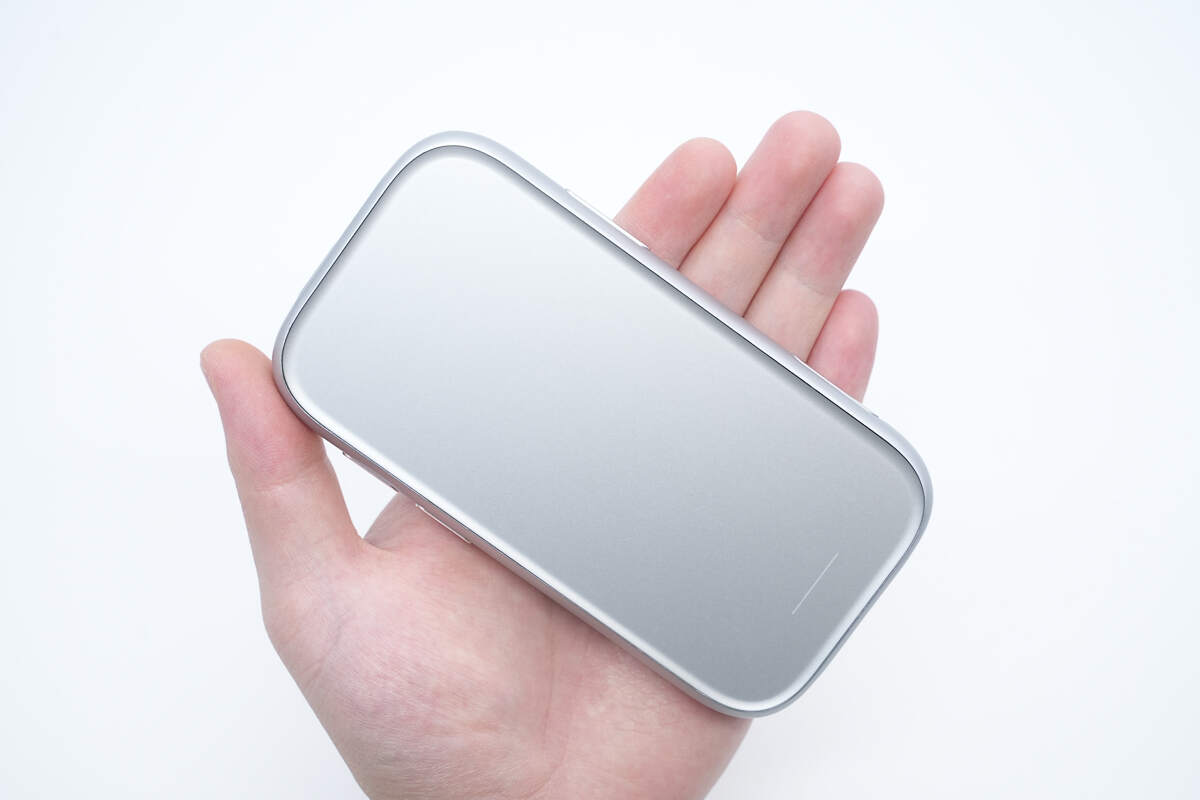
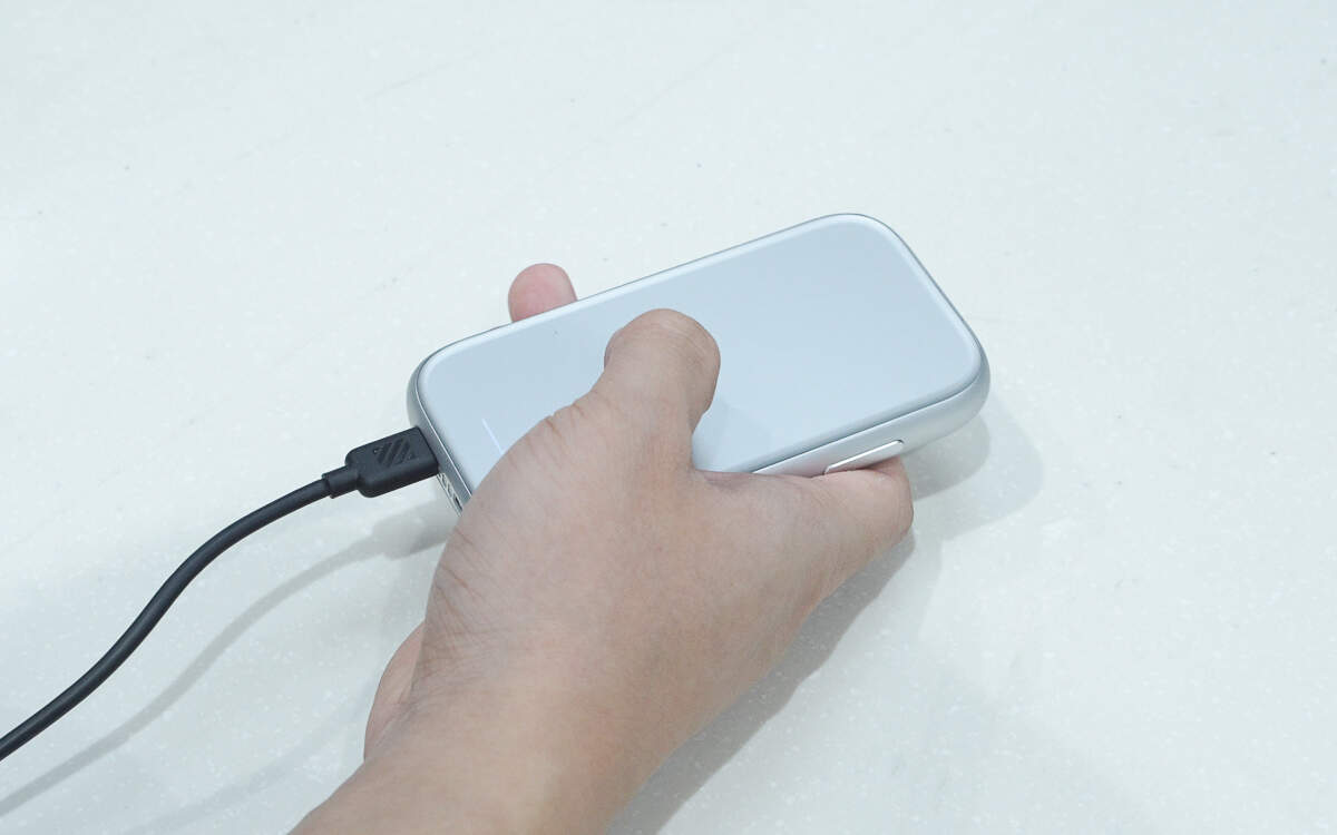
That's how big it is in the hand.
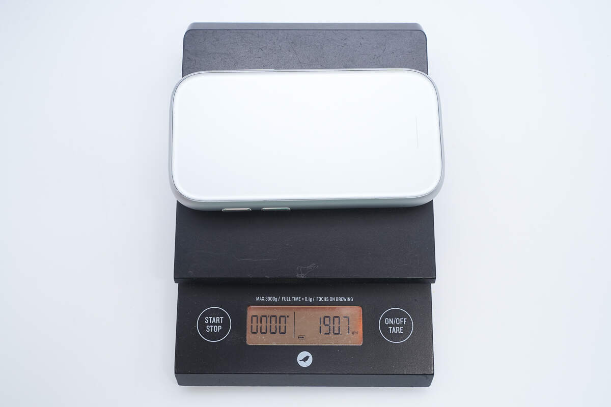
The weight is about 190.7 g (6.73 oz).
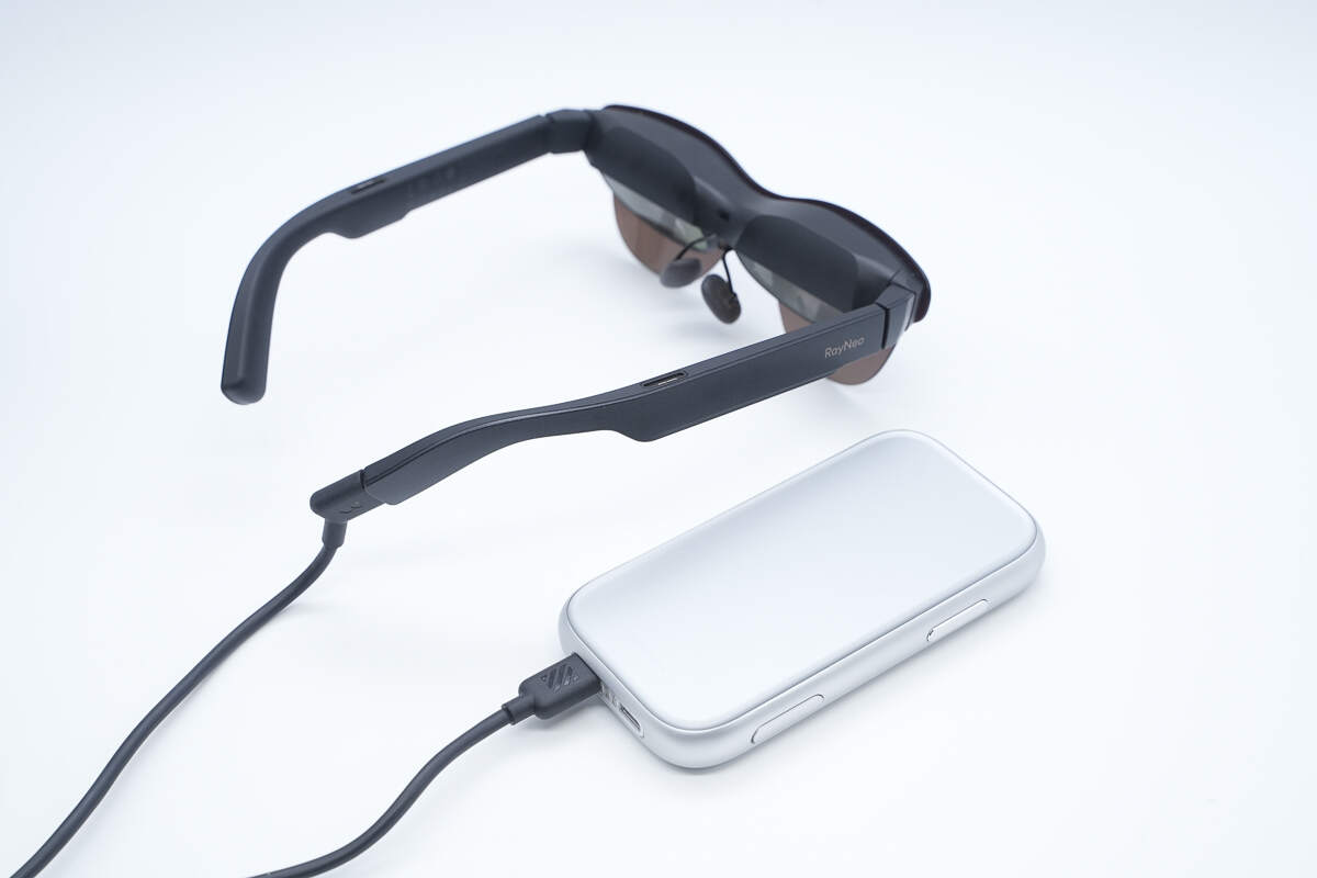
Connect the RayNeo Air 3S Pro glasses to the RayNeo Magic Box 2.
During use, operate the device via the touch panel on the front.
The status indicator light turns on during use.
Teardown
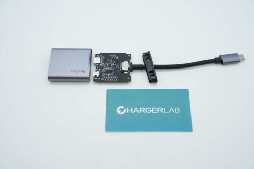
Next, let's take it apart to see its internal components and structure.
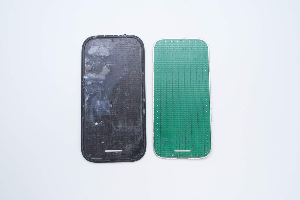
First, pry open the touch panel along the seam at the edge of the panel.
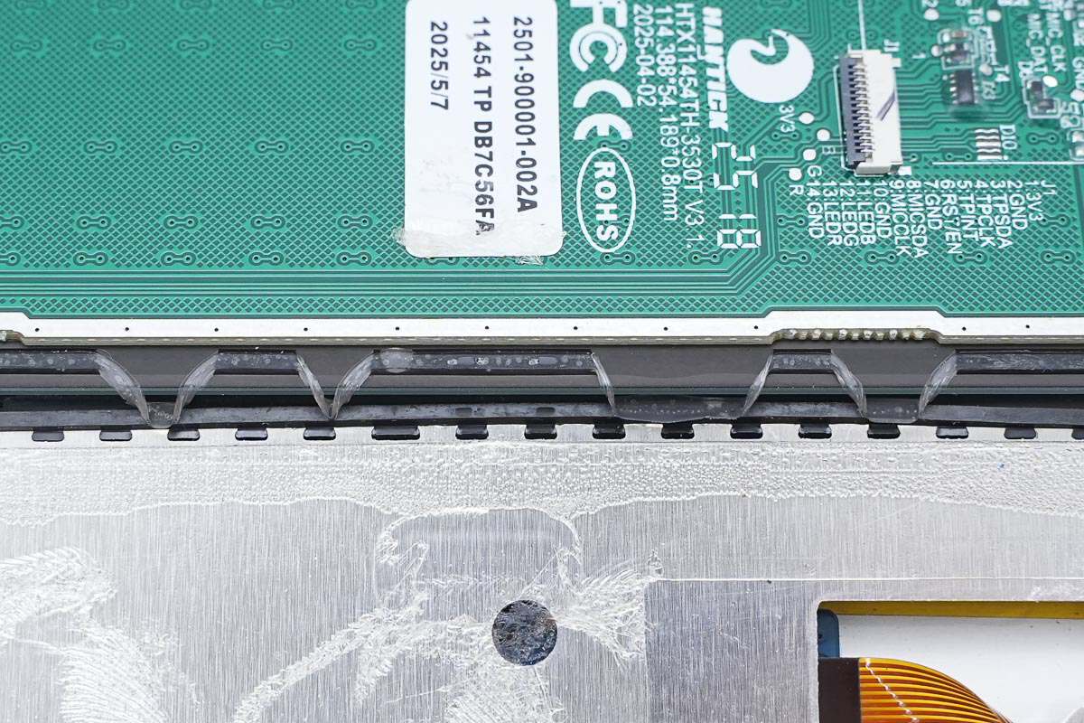
The touch panel is connected to the PCB via a ribbon cable.
The touch panel is attached to the casing with double-sided adhesive.
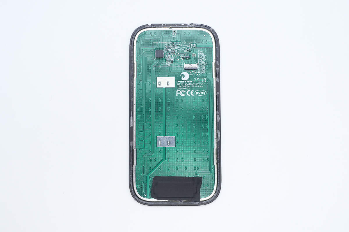
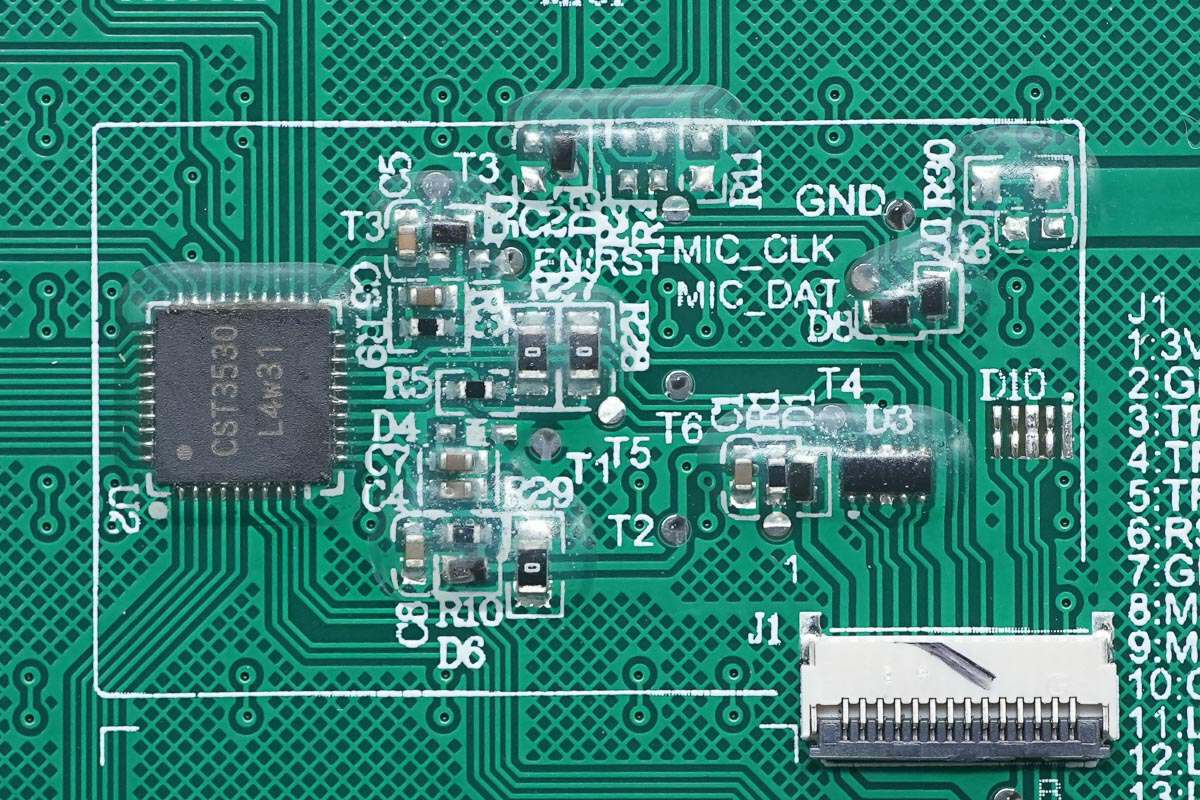
The touch panel includes a ribbon cable socket, a touch controller chip, and indicator lights.
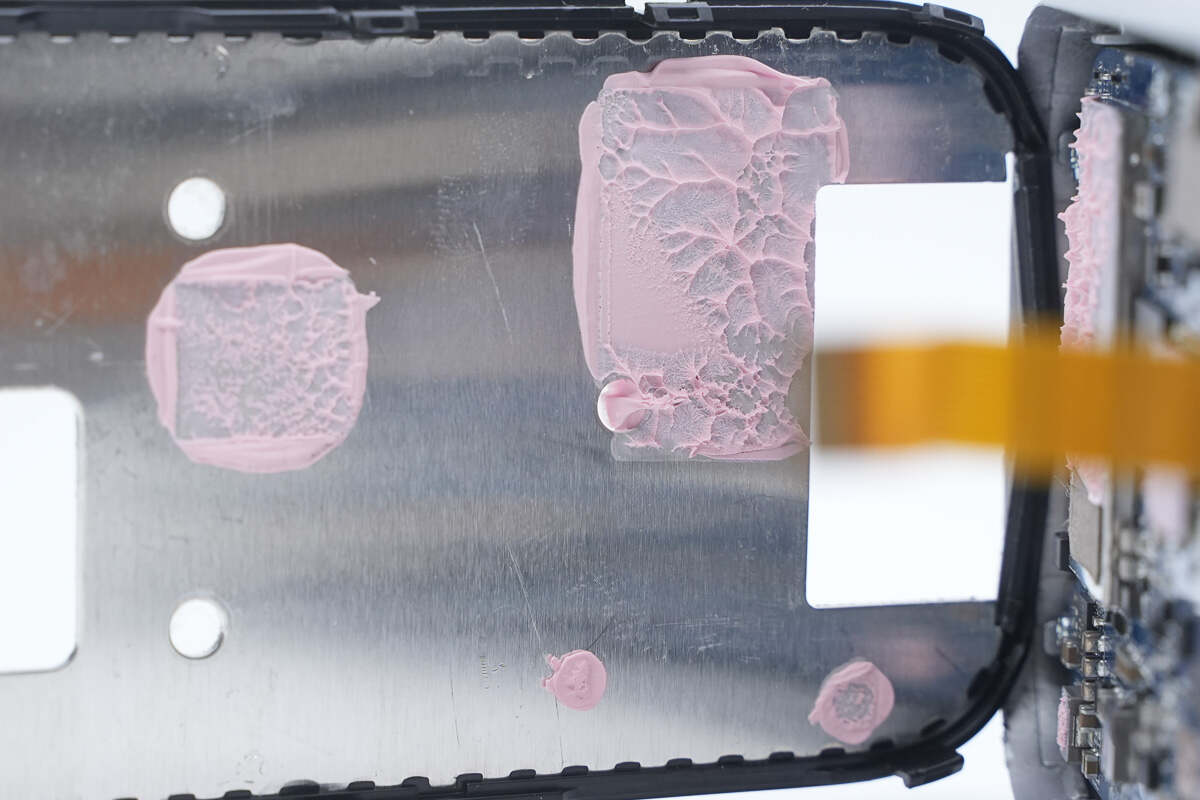
The components are sealed and protected with adhesive.
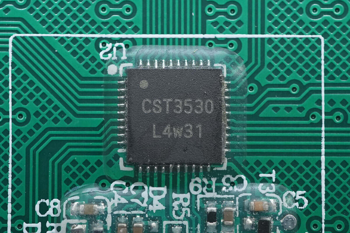
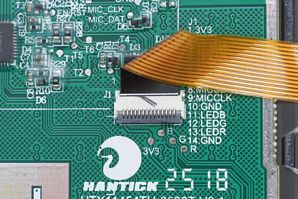
The touch controller chip is from HYNITRON, model CST3530. It features a high-performance capacitive sensing circuit and a DSP module, supports 10-point touch, 30 drive/sense channels, and comes in a QFN40 package.
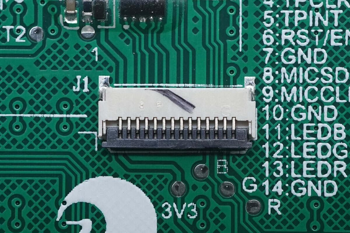
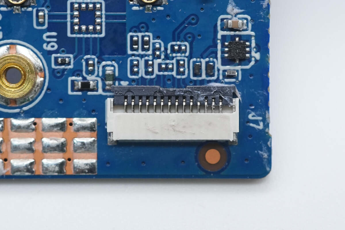
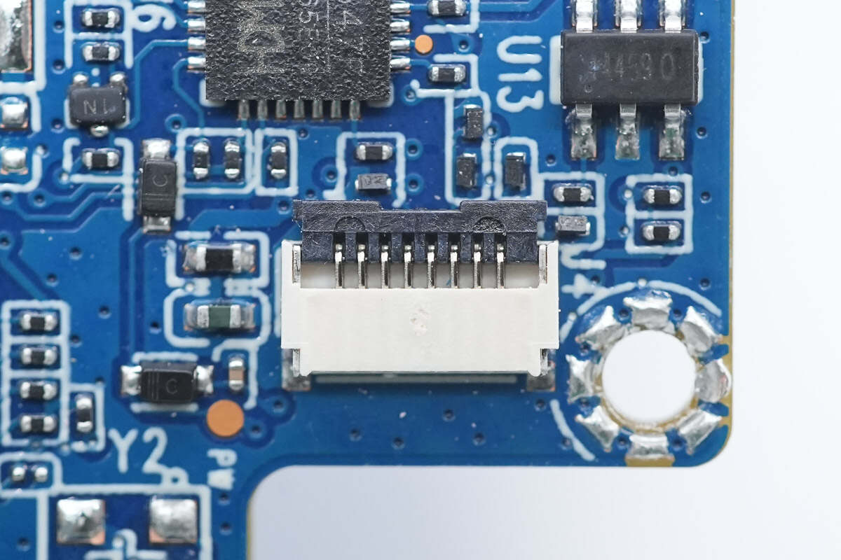
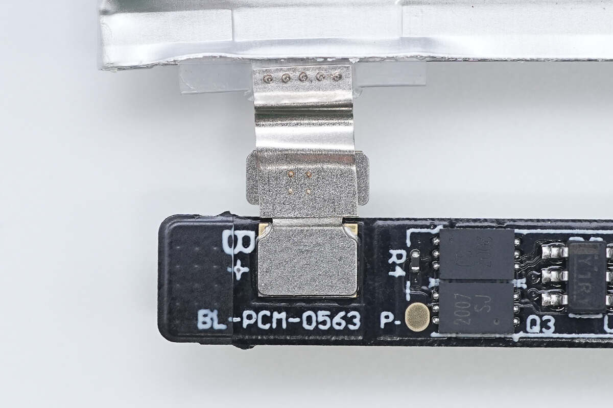
Close-up of the ribbon cable socket connecting to the PCBA module.
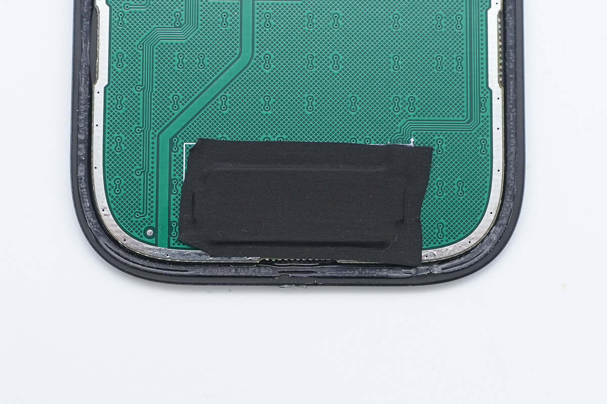
The status indicator light is covered with a light-blocking adhesive tape.
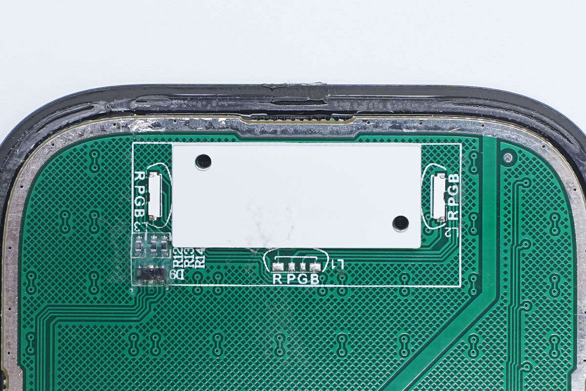
Under the adhesive tape, there is a light shield and an RGB LED.
A TVS array is used for electrostatic protection.
The touch PCB is attached to the inside of the casing with double-sided adhesive.
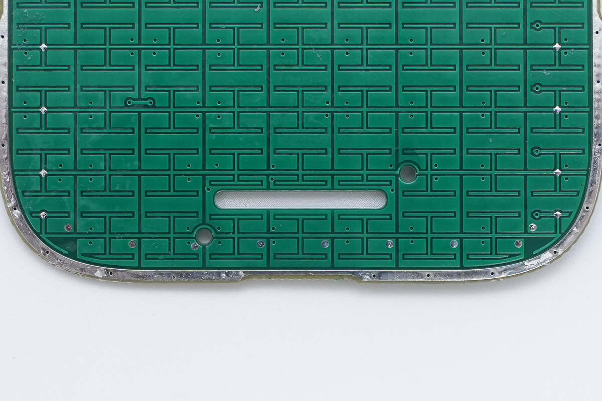
Close-up of the touch electrodes above the touch PCB.
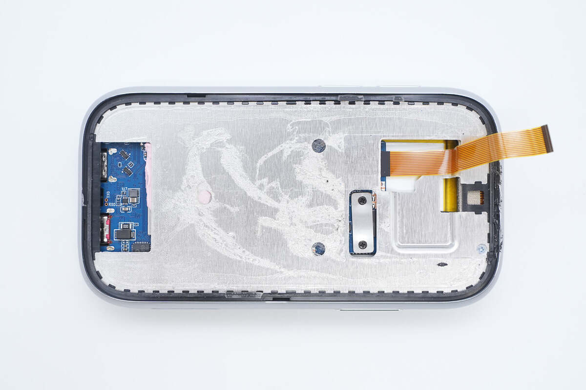
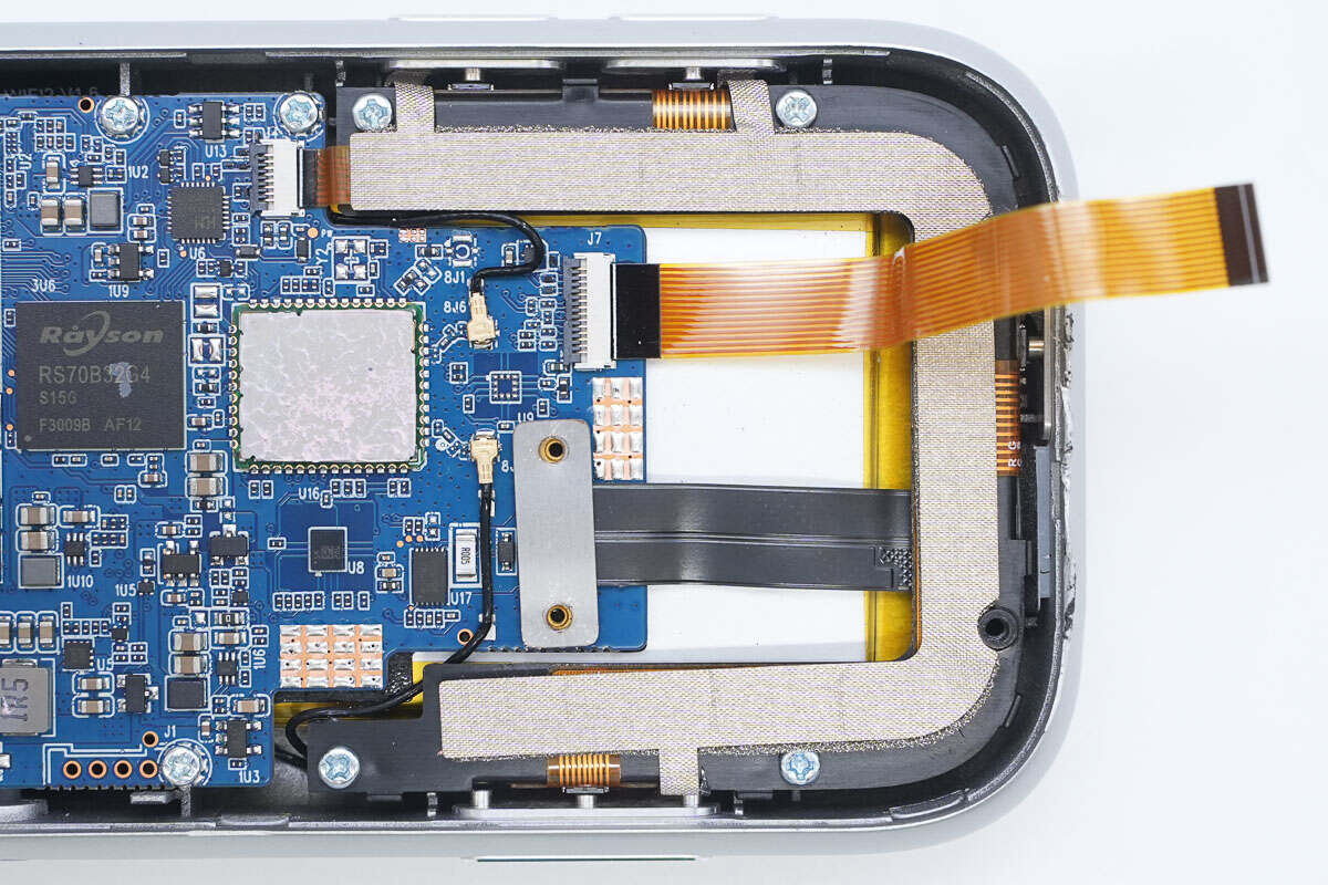
There is a mounting bracket inside the casing.
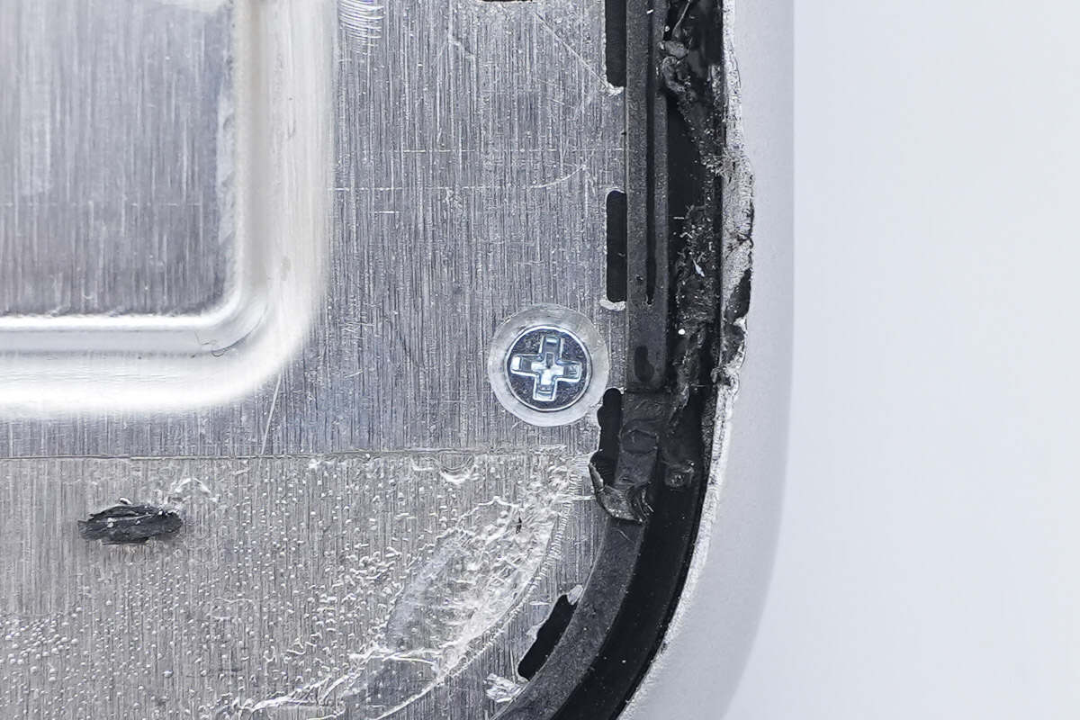
The bracket is secured with screws.
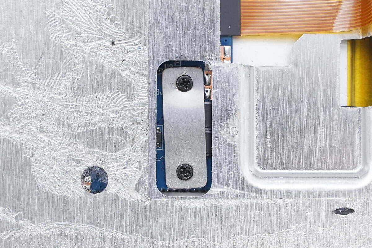
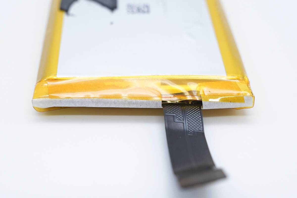
The battery ribbon cable is secured with a screw-down clamp.
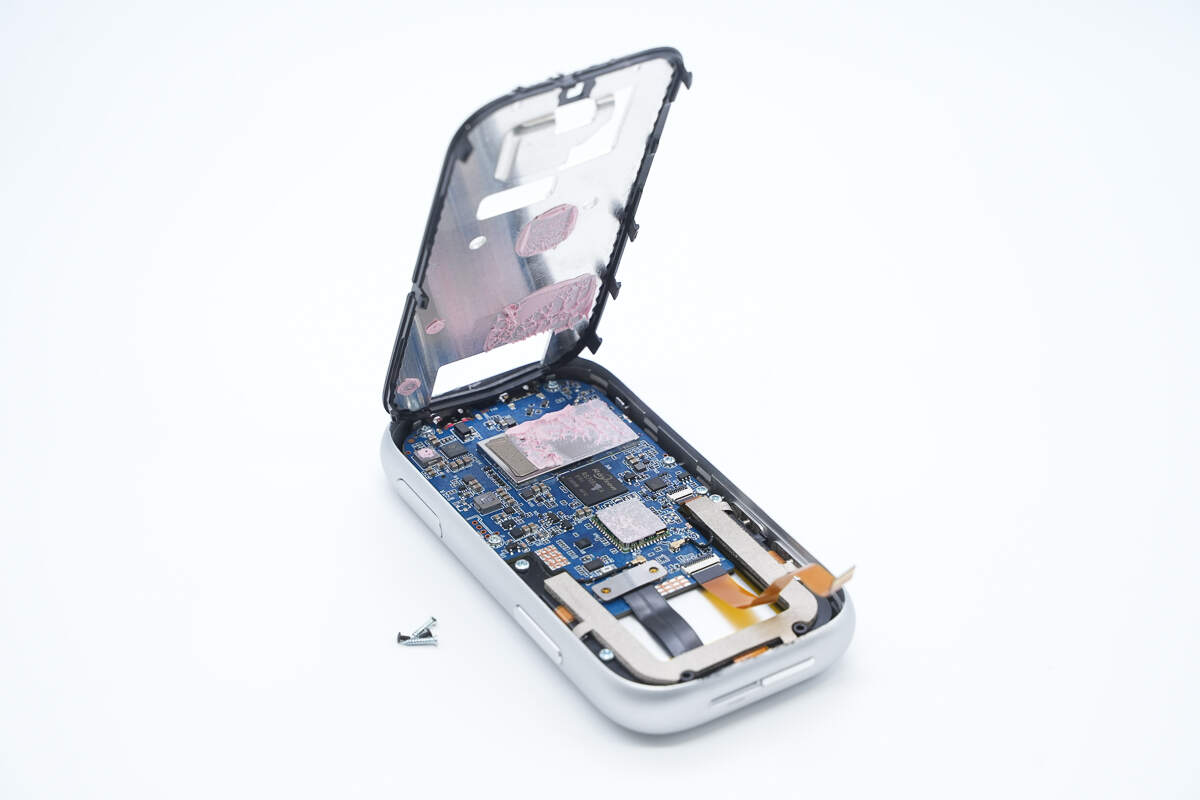
Unscrew the screws and remove the mounting bracket.
Pink thermal gel is applied to the heat-generating chip area.
The shielding cover, wireless communication module, and inductors are coated with pink thermal gel.
The ribbon cable for the side buttons is attached to the plastic bracket.
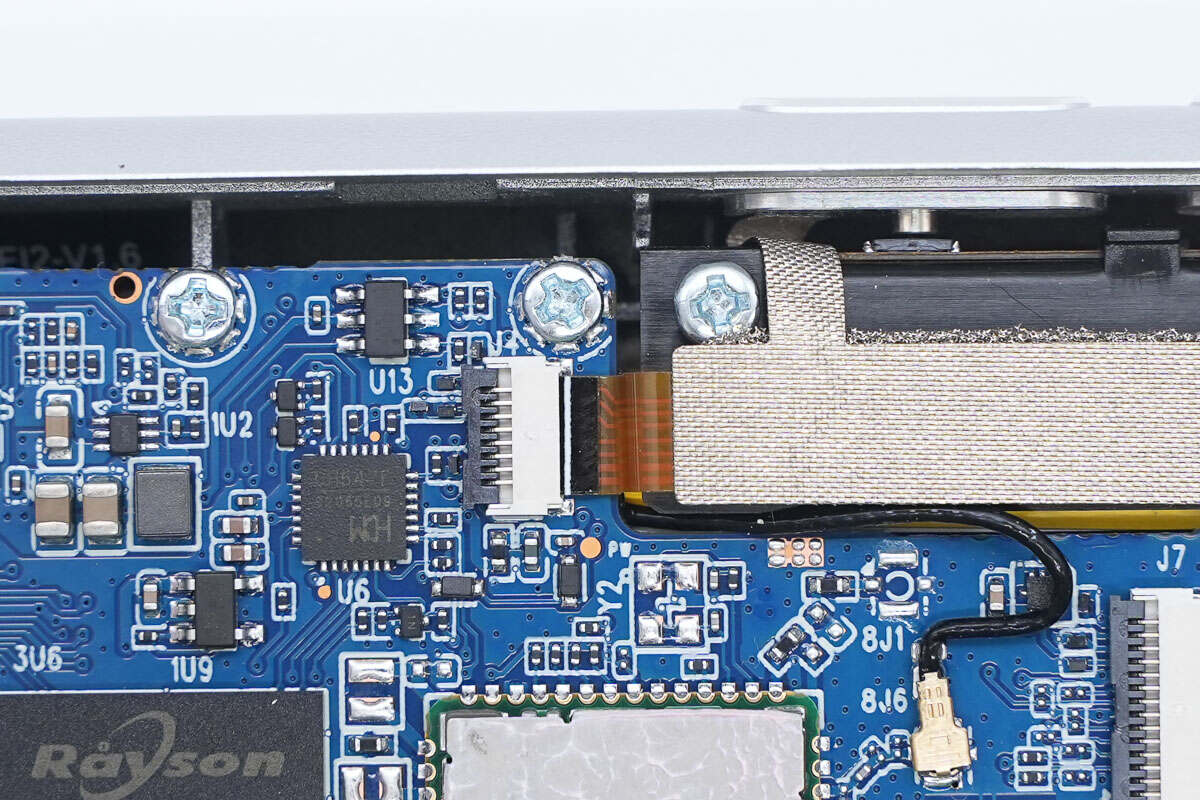
Close-up of the ribbon cable connector.
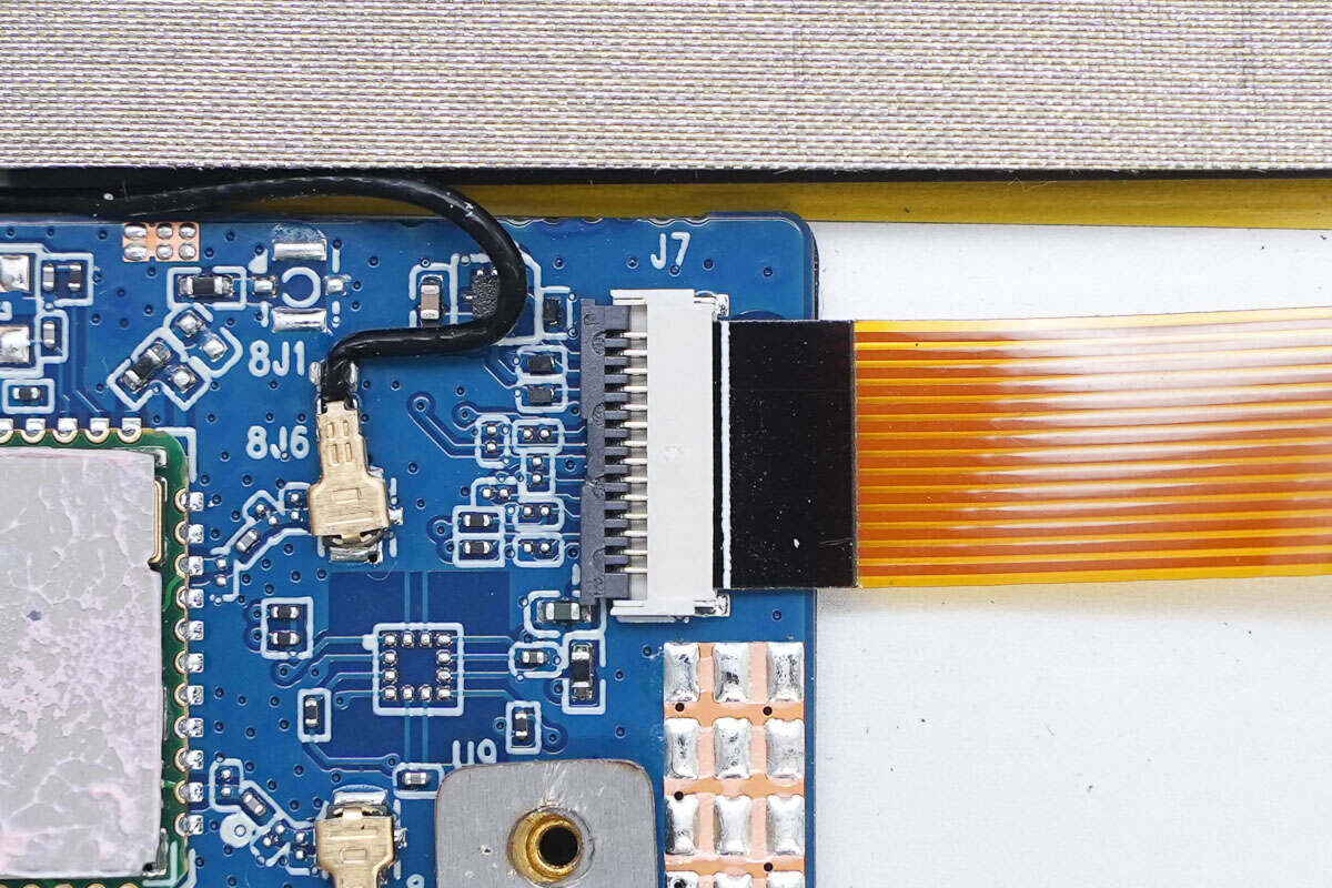
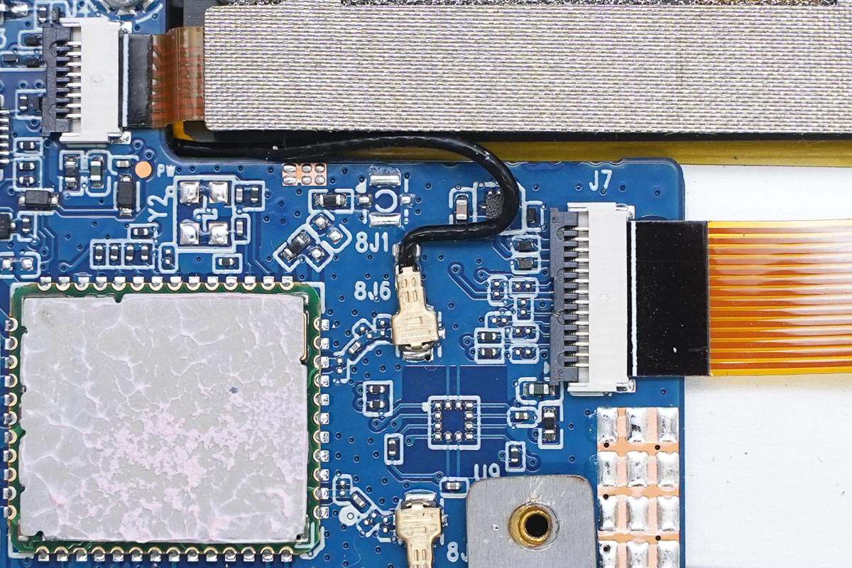
Close-up of the ribbon cable connecting to the touch panel.
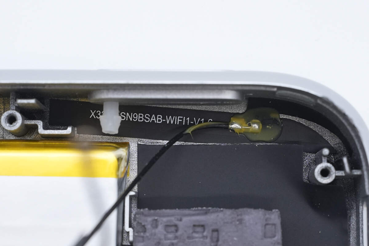
The wireless antenna is connected via a feeder cable.
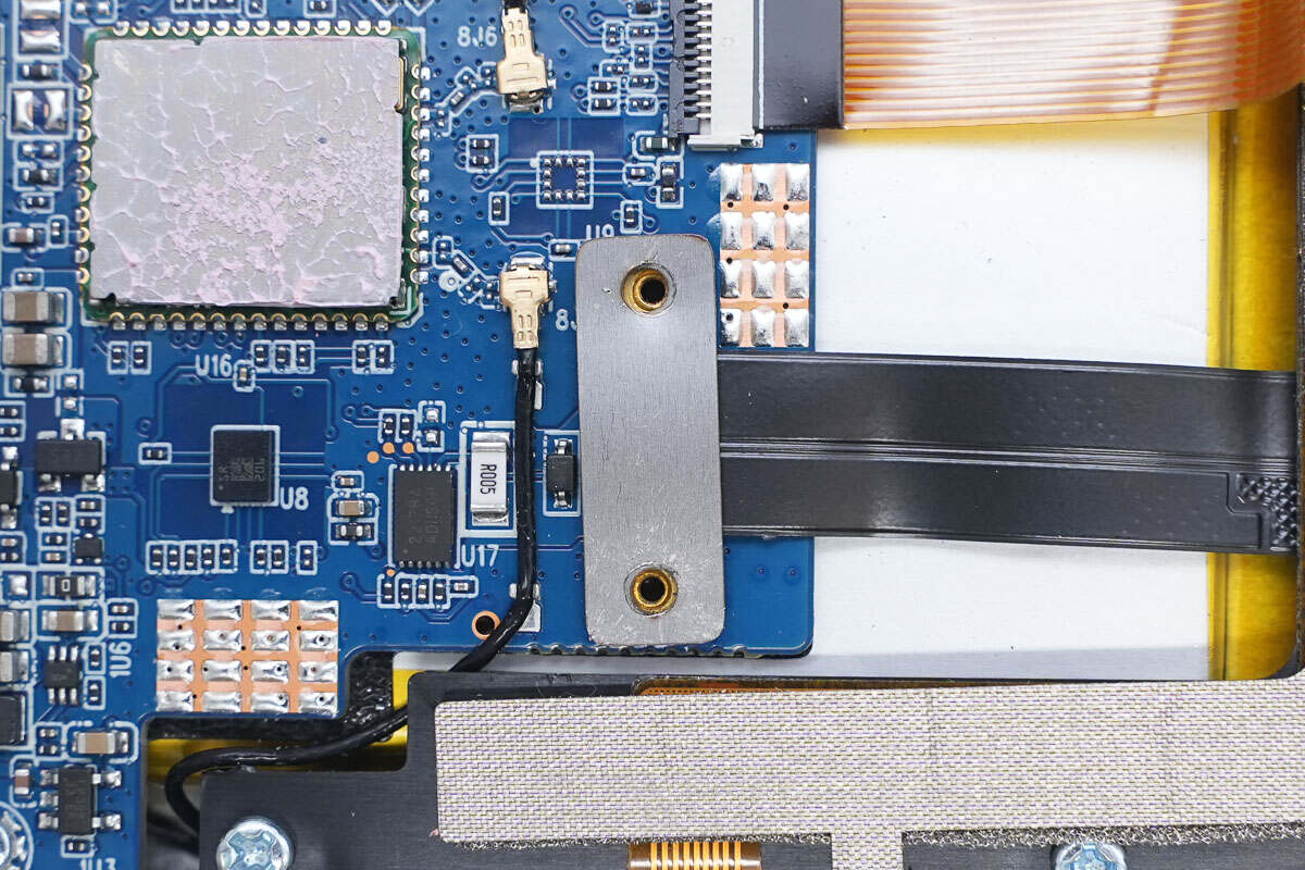
The battery ribbon cable socket is secured with a clamp plate.
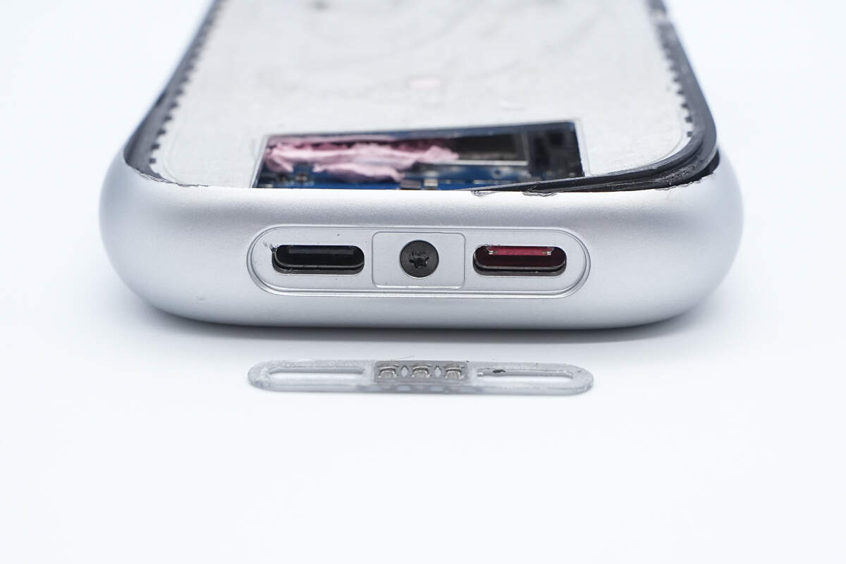
Remove the USB-C port cover. Inside, there is a screw.
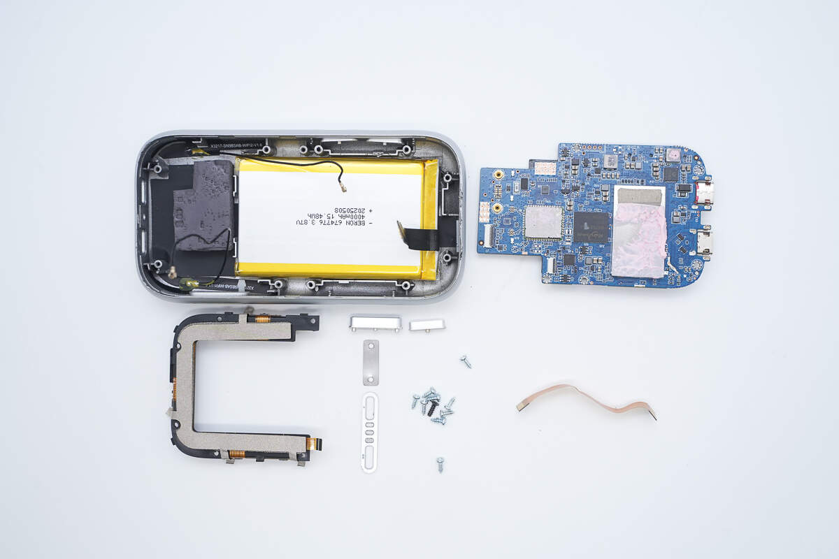
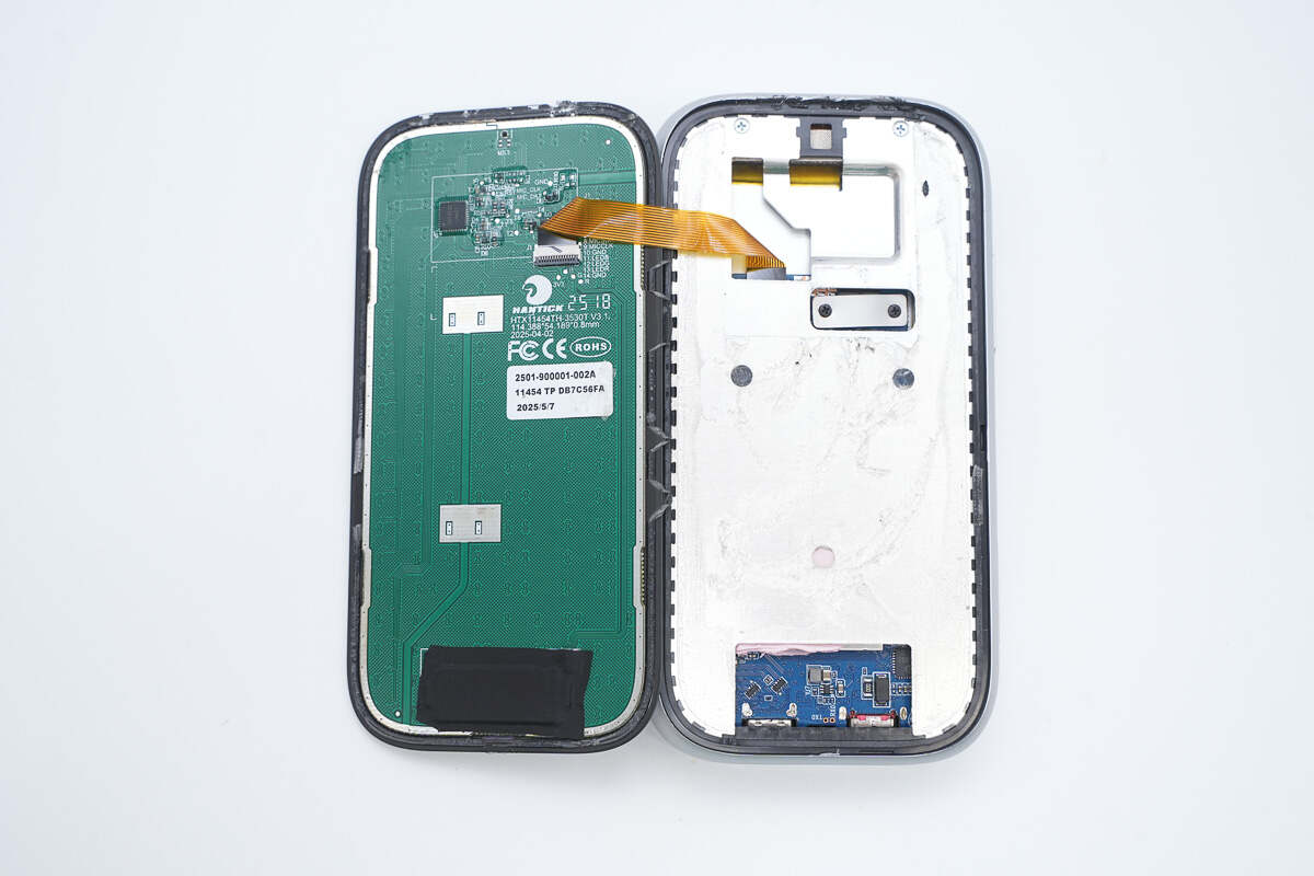
Remove the bracket, then take out the PCBA module and the button bracket.
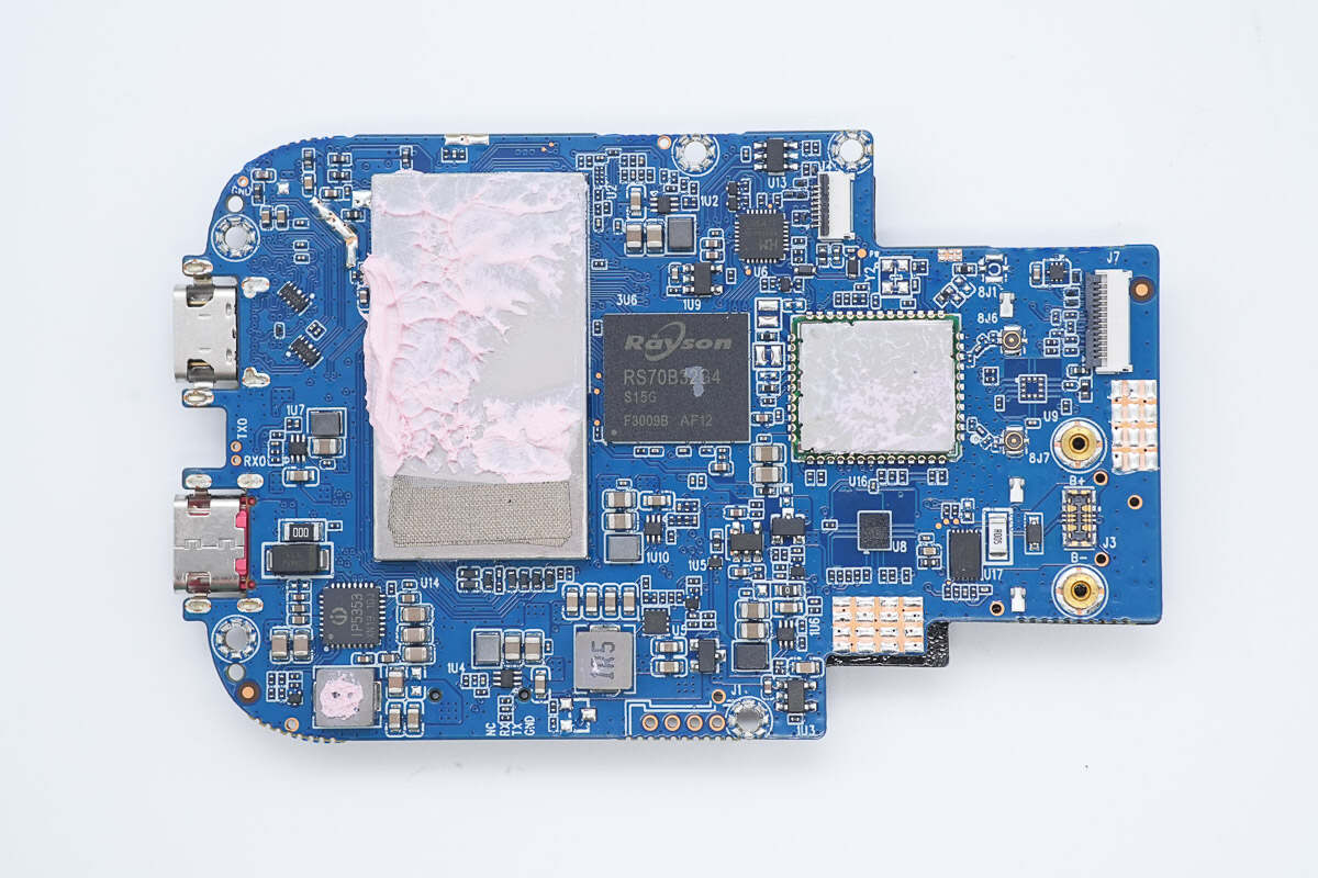
The front of the PCBA has a shielding cover, and the wireless module is also equipped with a shielding cover.
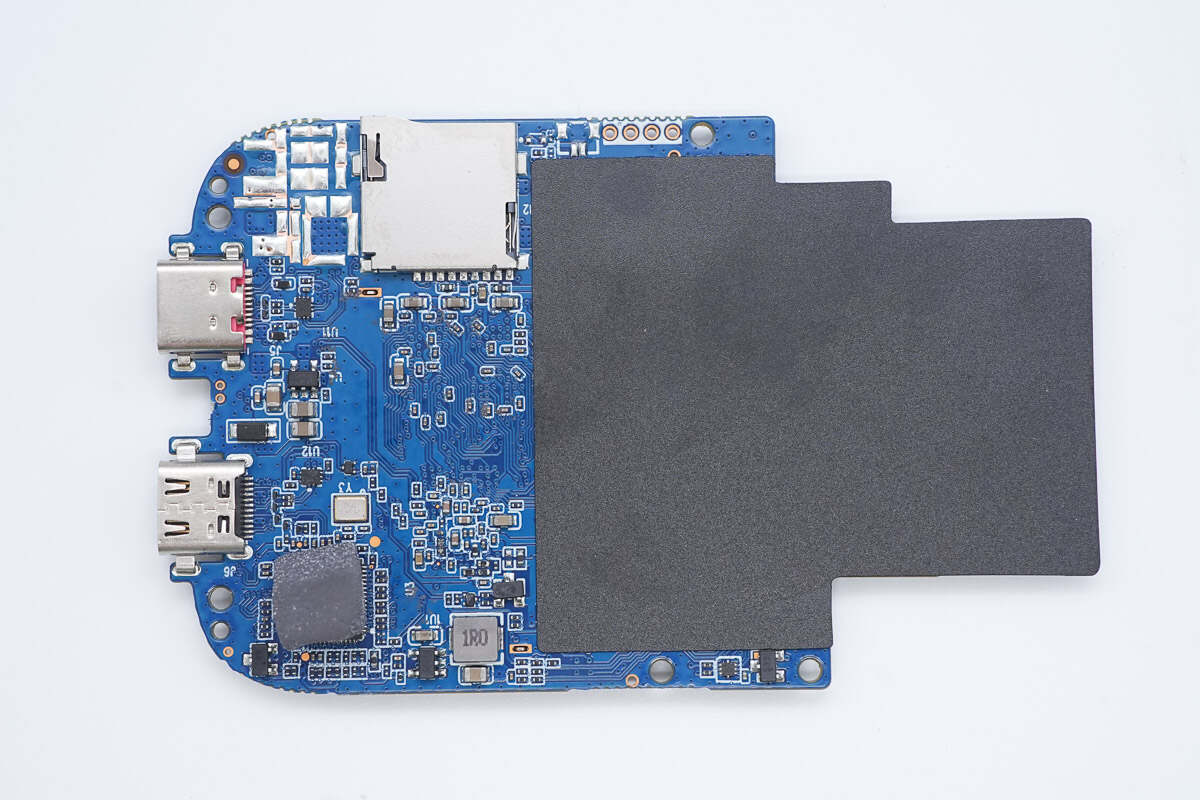
The back features a TF card slot, with a mylar sheet insulation attached on the right side.
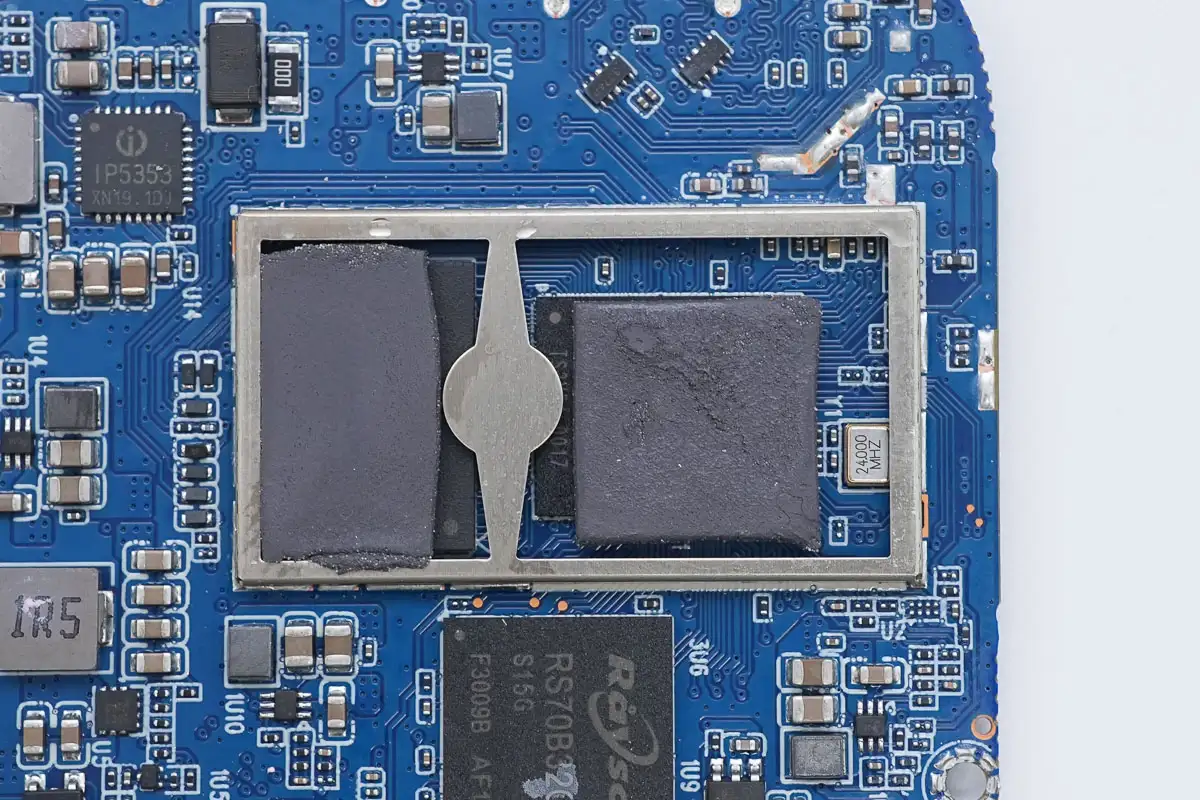
Two chips inside the shielding cover are covered by thermal pads.
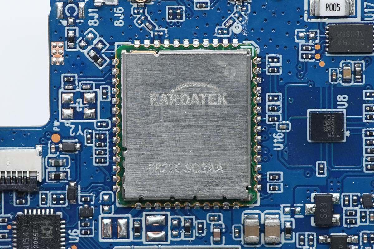
The WiFi module is from Eardatek and contains the REALTEK RTL8822 chip.
A chip in the lower right corner of the back is covered with a thermal pad.
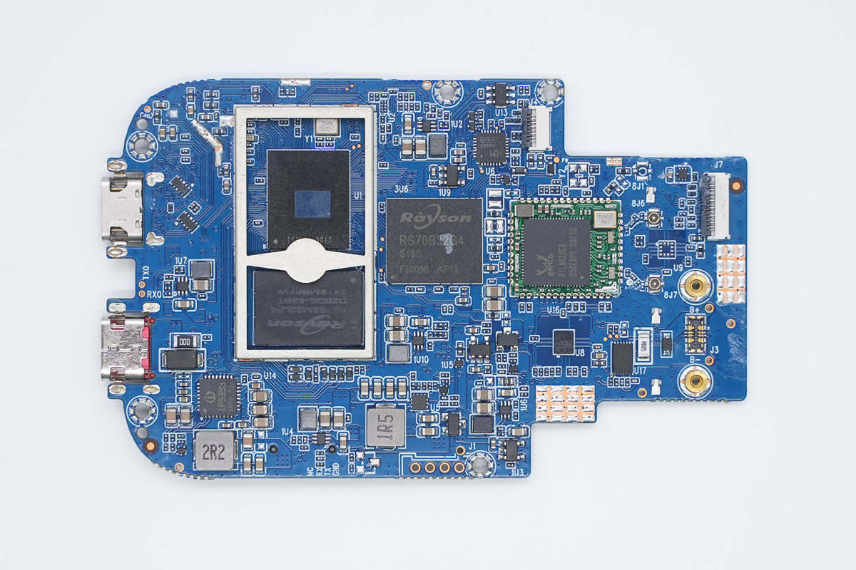
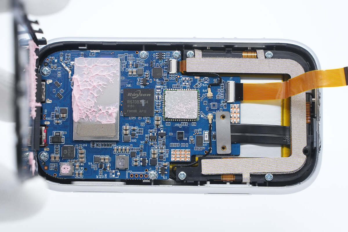
Front view of the PCBA module: inside the shielding cover are the master control chip and memory chip. On the right side are the eMMC storage and the WiFi module. Above them is the MCU. The lower left corner houses the battery charging chip and boost converter chip. On the right side are the fuel gauge and sampling resistor.
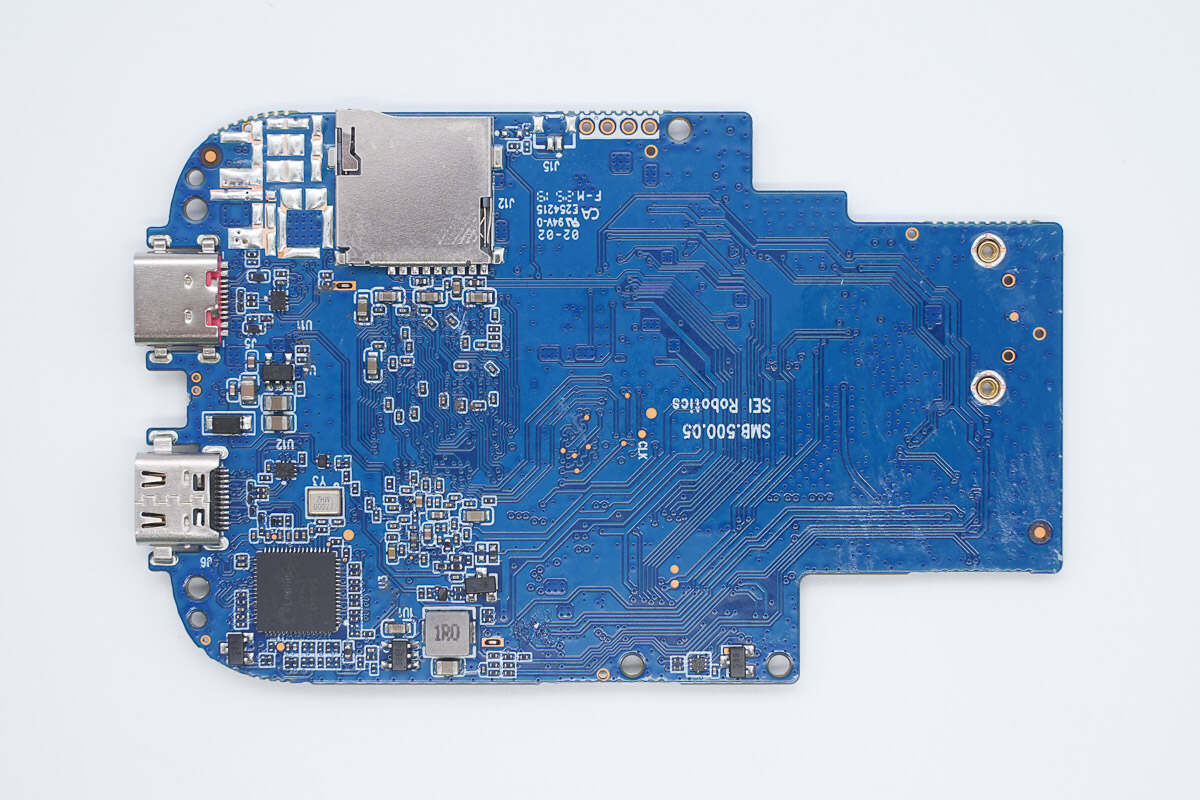
The back features a TF card slot and a video conversion chip.
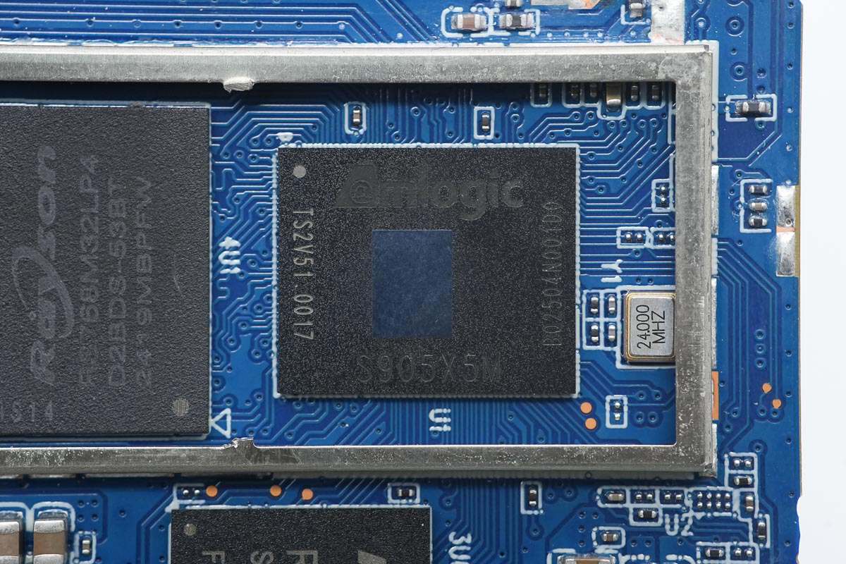
The master control chip is from Amlogic, model S905X5M. It is built with a 6nm process, features a quad-core ARM Cortex-A55 CPU, an ARM Mali-G310 V2 GPU, supports AISR and HDMI 2.1b, and comes in a BGA package.
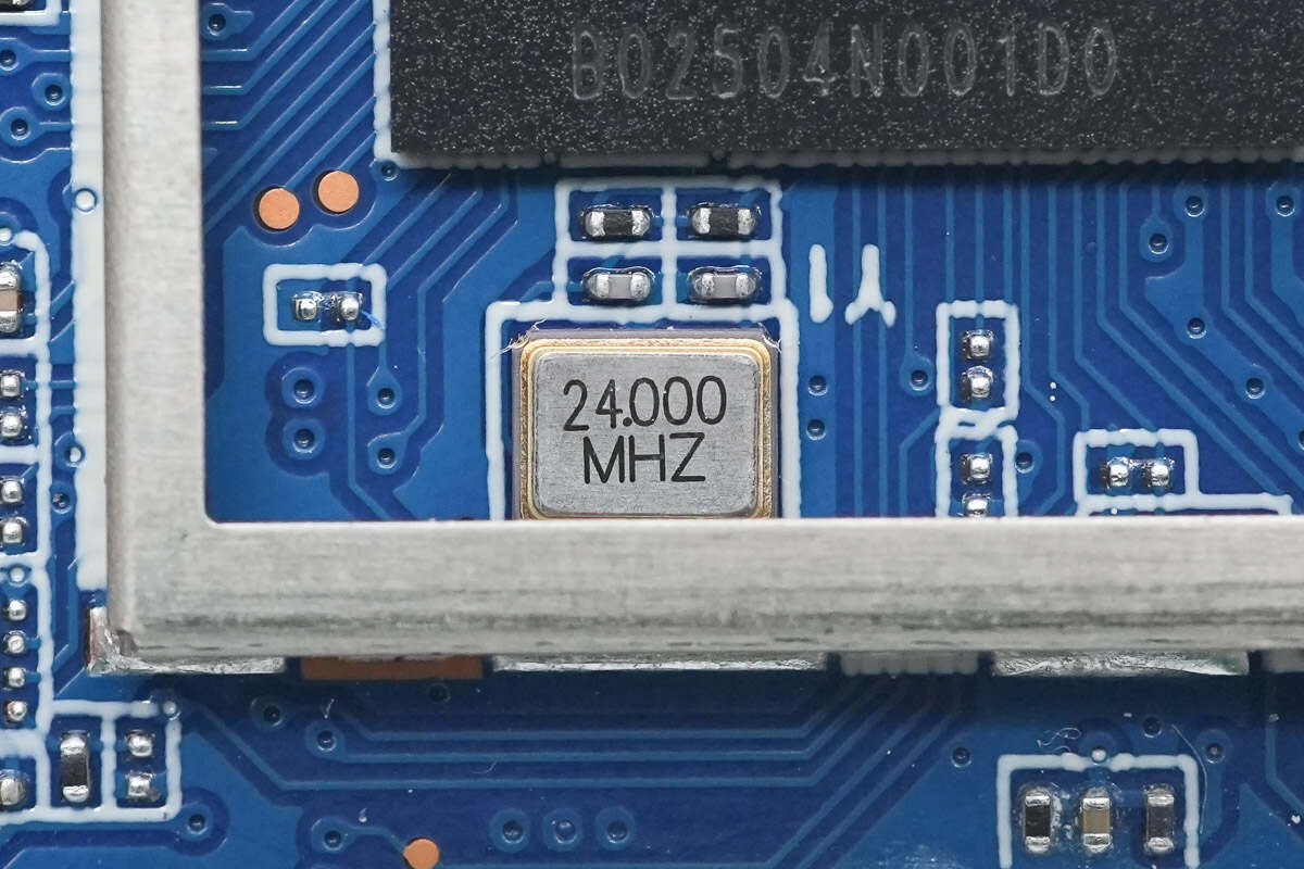
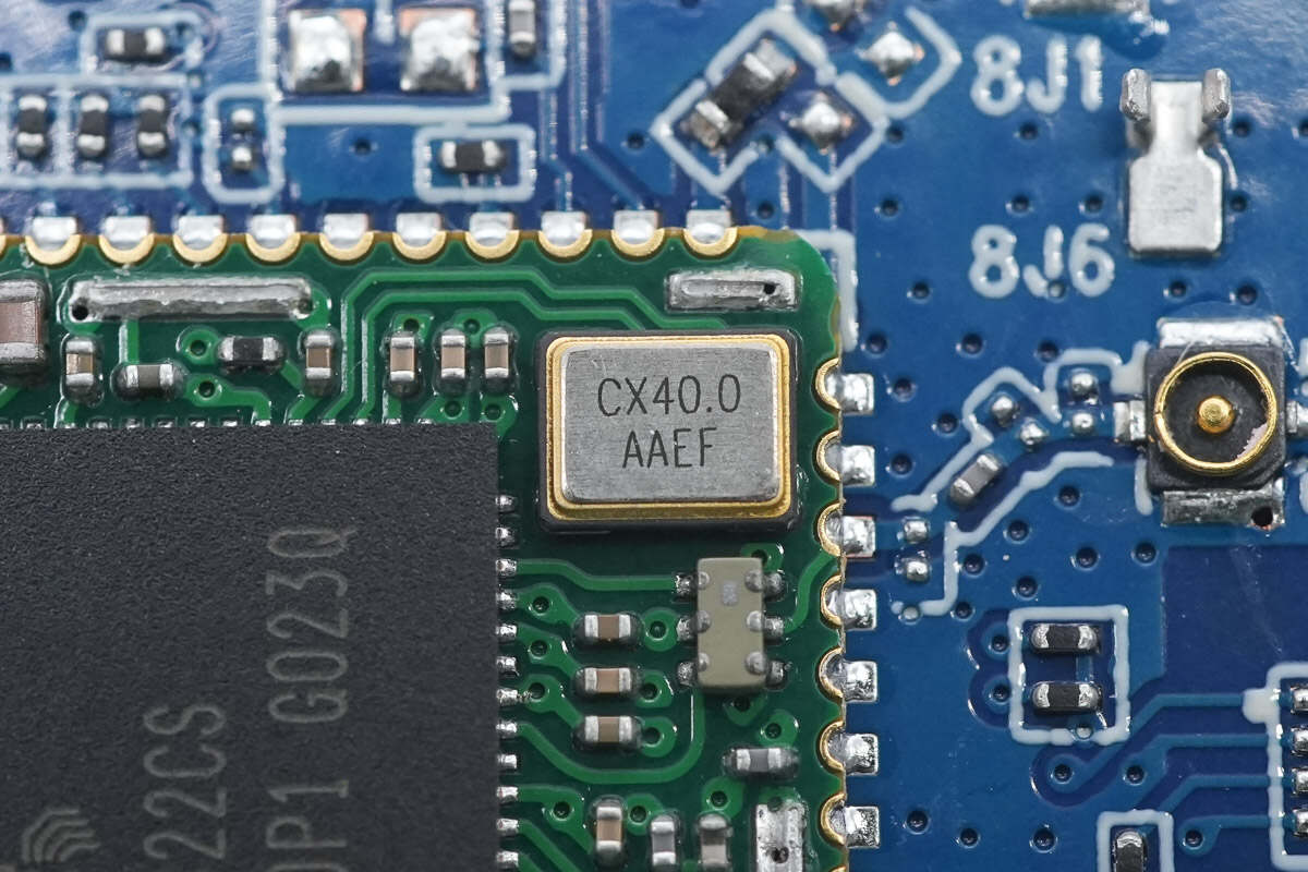
Close-up of the 24.000 MHz clock crystal oscillator.
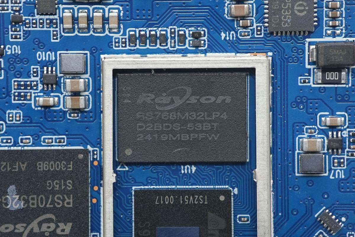
The memory chip is from Rayson, model RS768M32LP4D2BDS-53BT. It is LPDDR4X memory with a speed of 3733 Mbps, a capacity of 3GB, and comes in an FBGA 200-ball package.
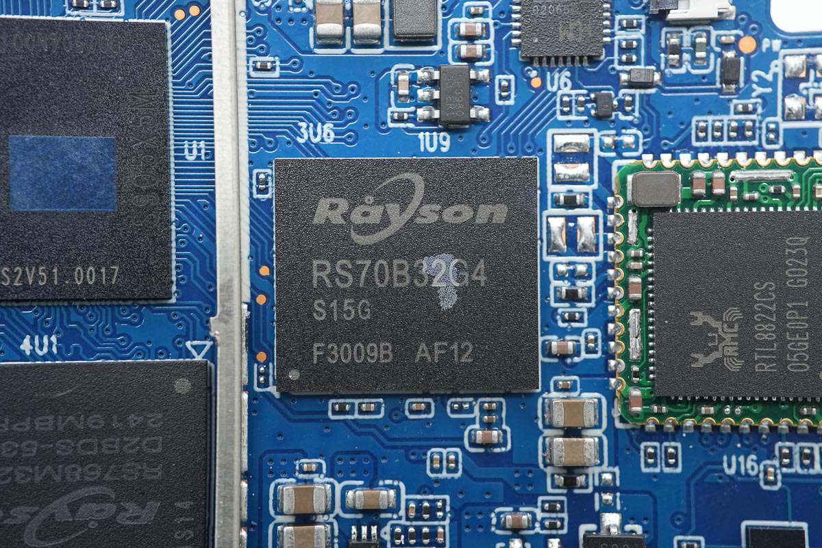
The eMMC storage is from Rayson, model RS70B32G4S15G. It uses an eMMC 5.1 interface, has a capacity of 32GB, and comes in an FBGA153 package.
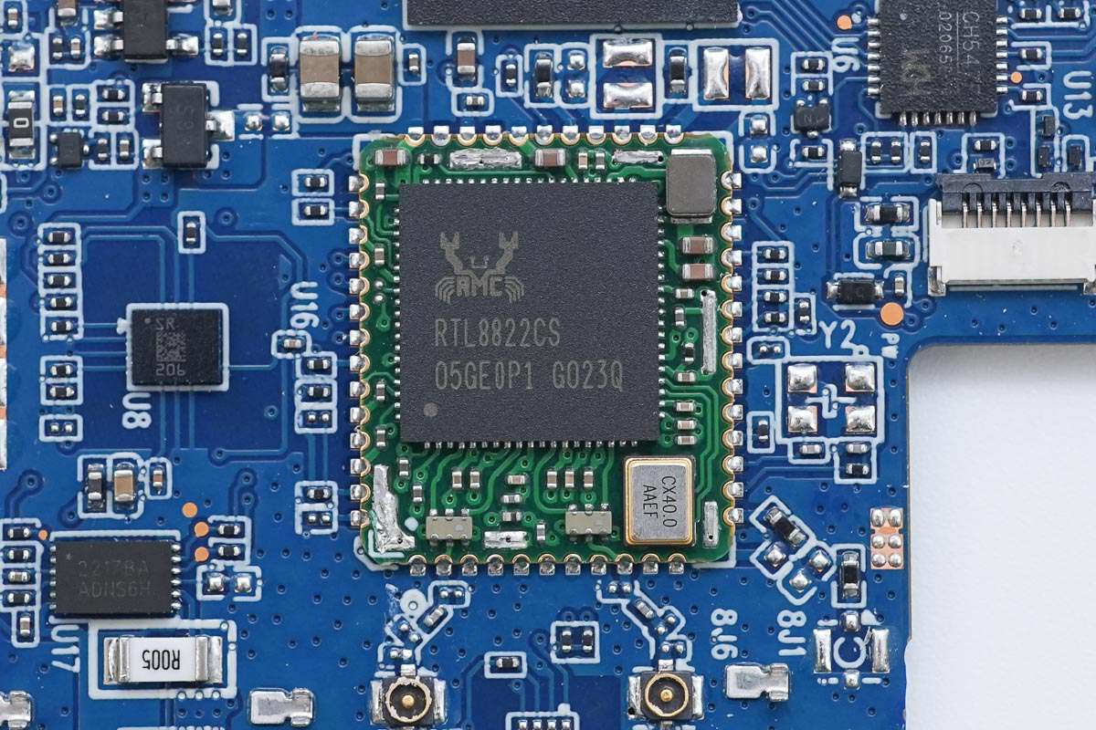
The wireless chip is from REALTEK, model RTL8822CS. It supports 2.4GHz and 5GHz bands, complies with 802.11b/g/n/ac wireless standards, supports SDIO and UART interfaces, and comes in a QFN-76 package.
Close-up of the external buck inductor next to the chip.
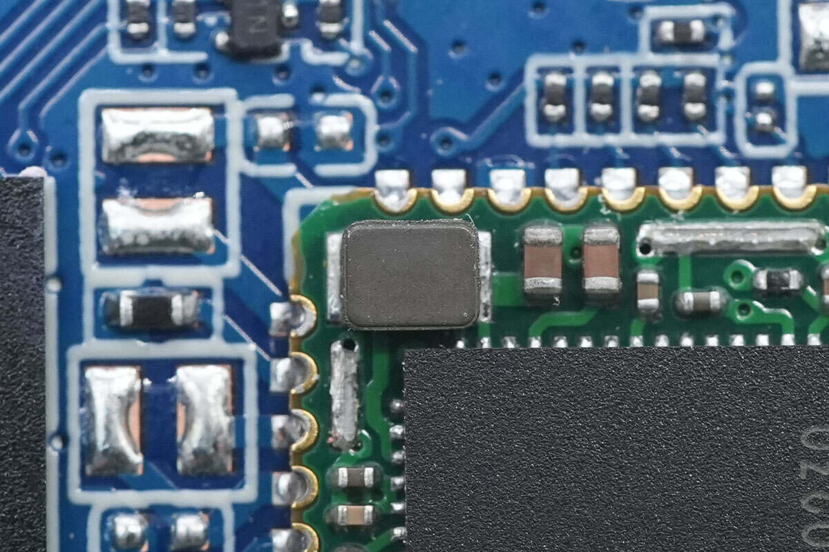
Close-up of the external clock crystal oscillator next to the chip.
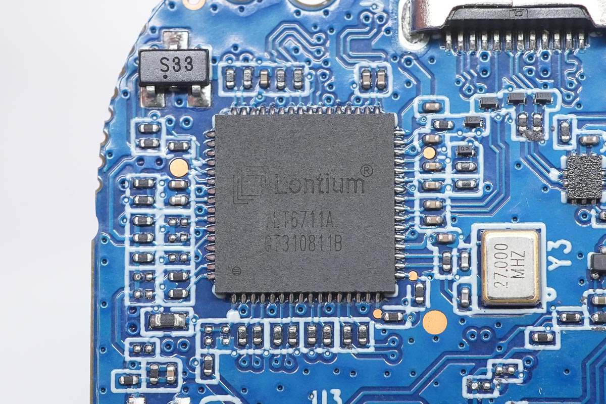
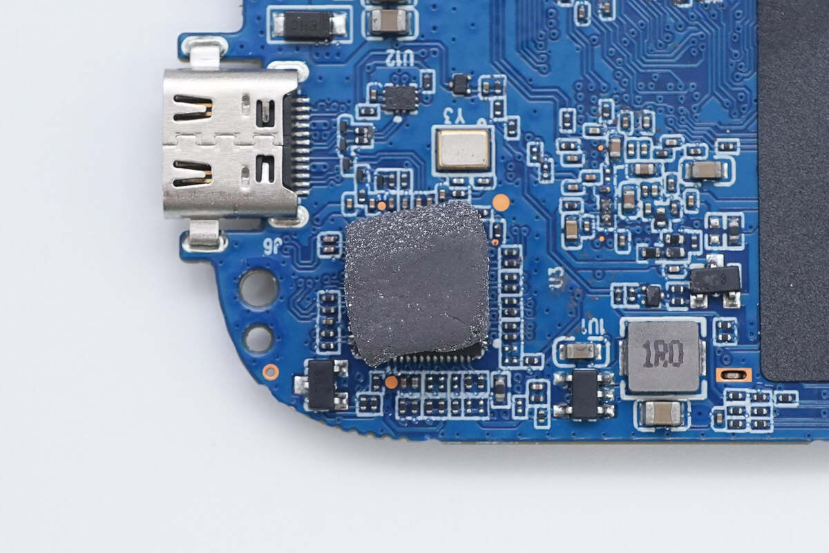
The video conversion chip is from Lontium, model LT6711A. It converts HDMI 2.0 input to DP 1.2 output, integrates a PD controller internally, and comes in a QFN64 package.
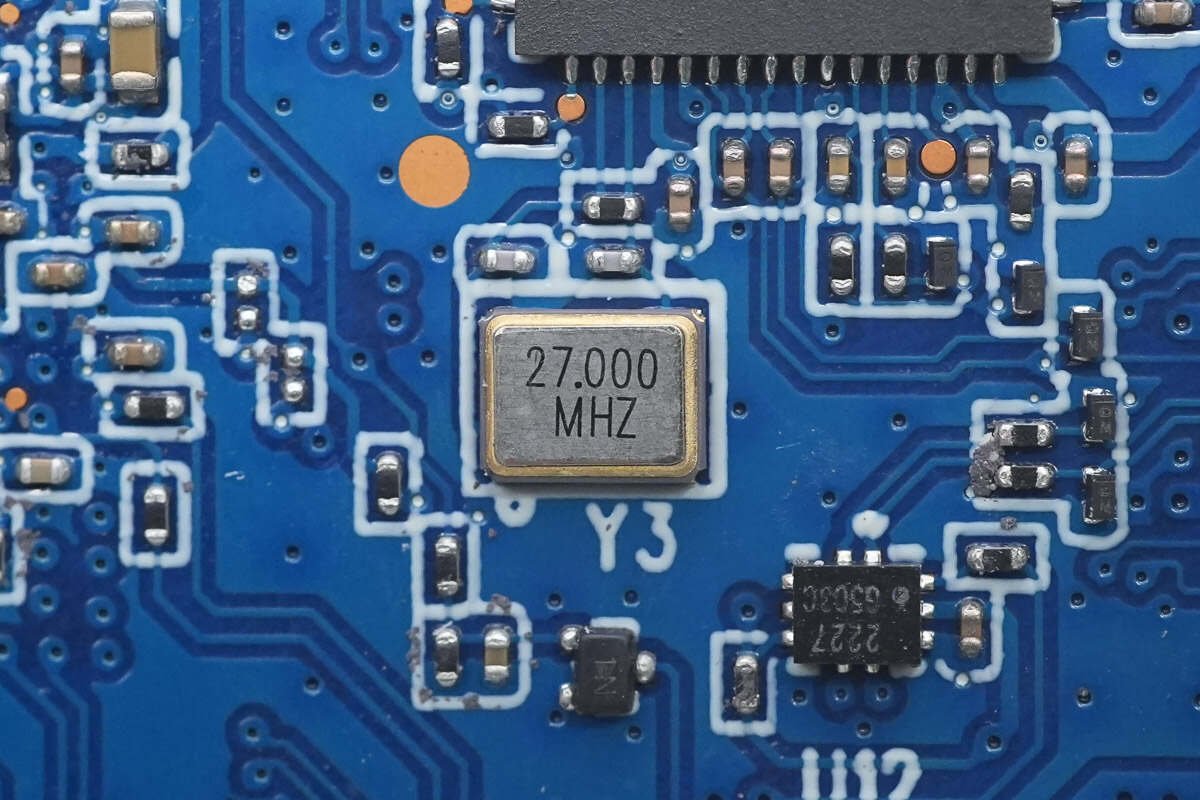
The chip is paired with an external 27.000 MHz clock crystal oscillator.
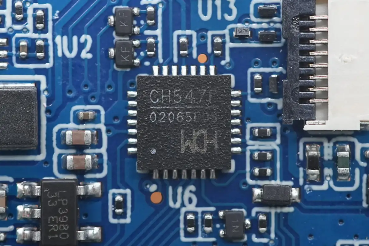
The MCU is from WCH, model CH547F. It is an enhanced E8051 core microcontroller with 64KB program ROM, 1KB + 256B RAM, USB interface, built-in ADC, UART, and SPI interfaces, and comes in a QFN28 package.
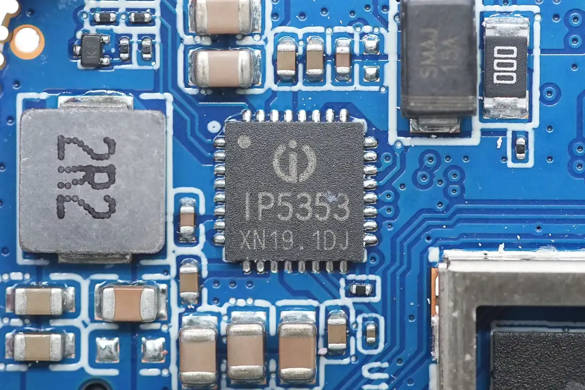
The battery charging chip is from Injoinic, model IP5353. It is an integrated power SOC for mobile power banks supporting multiple fast-charging protocols. It includes a synchronous buck-boost converter, battery charging management, and battery level indication, providing a complete power solution for fast-charging power banks.
The built-in synchronous switching charging system supports 18W charging with a battery charging current up to 5A. The synchronous boost converter supports 22.5W output and features automatic sleep mode. The IP5353 supports battery charging voltages of 4.2V, 4.3V, 4.35V, and 4.4V, as well as an external NTC for battery temperature protection. It comes in a QFN32 package.
Here is the information about Injoinic IP5353.
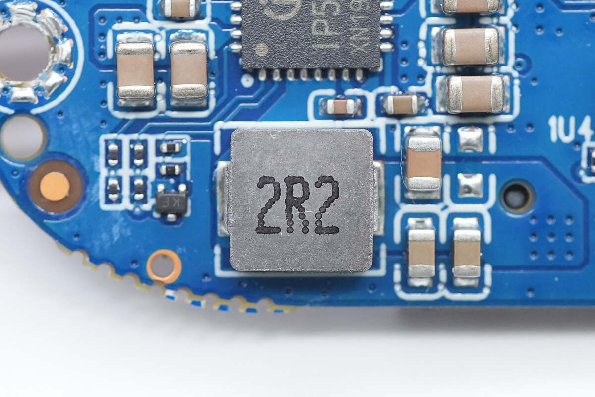
A 2.2μH alloy inductor is used for battery charging and discharging.
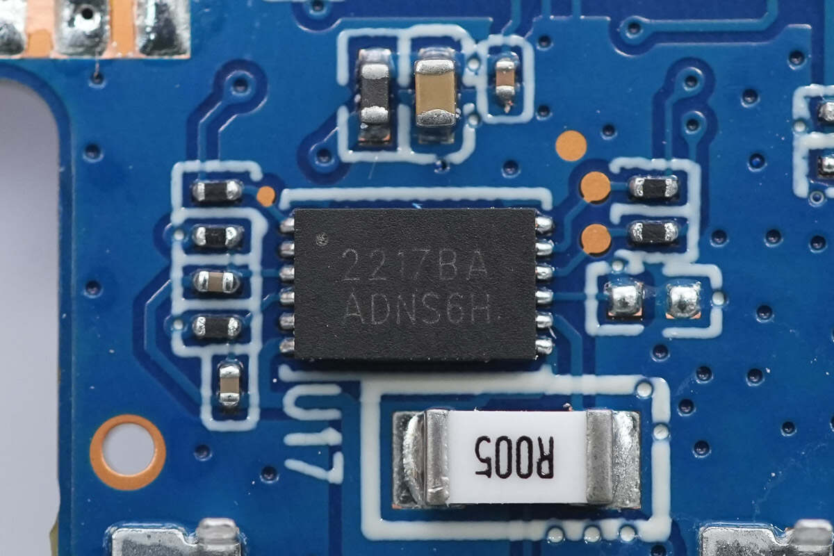
The battery fuel gauge is from Cellwise, model CW2217BAAD. It features a built-in 14-bit ADC for temperature and voltage measurement and a 16-bit ADC for current measurement. It supports a 1mΩ shunt resistor and is compatible with lithium manganese, lithium cobalt, and lithium polymer batteries. The chip comes in a DFN-12 package.
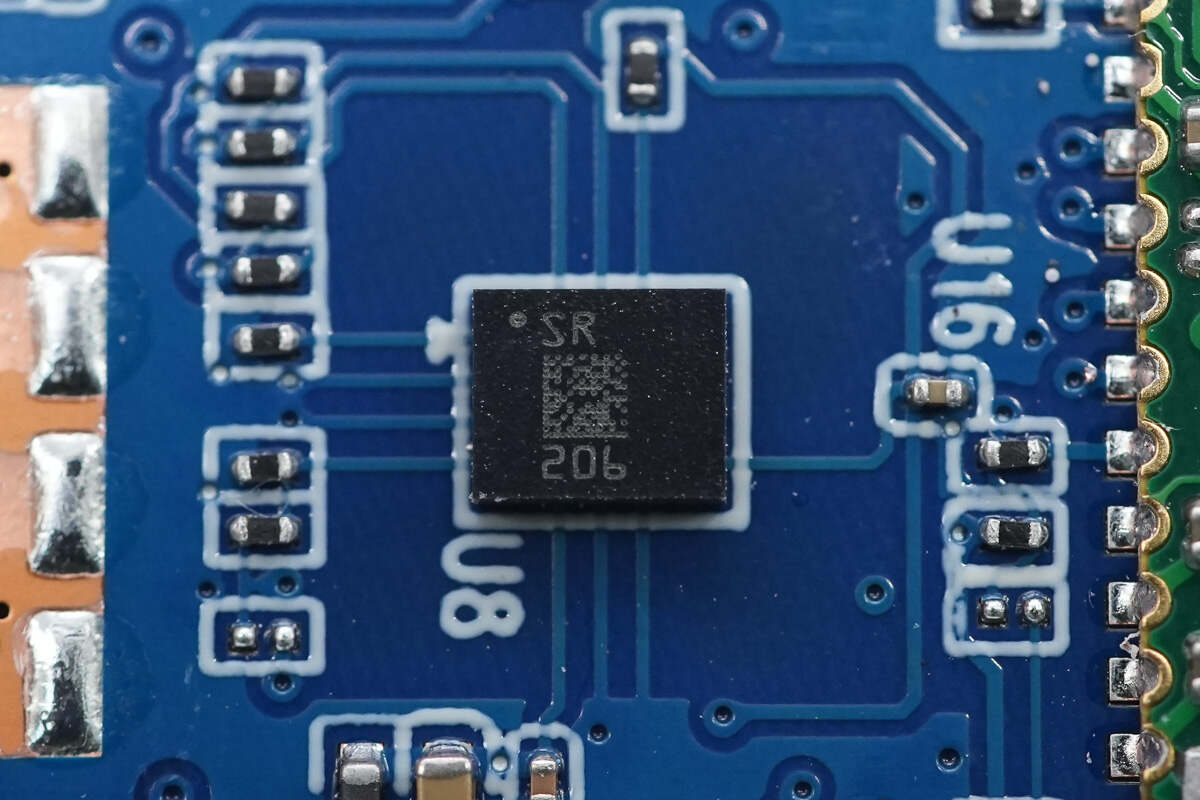
The accelerometer is from STMicroelectronics, marked with SR, model LSM6DSR. It features a built-in 3D digital accelerometer and 3D digital gyroscope, supports SPI, I2C, MIPI, and I3C interfaces, and comes in an LGA-14L package.
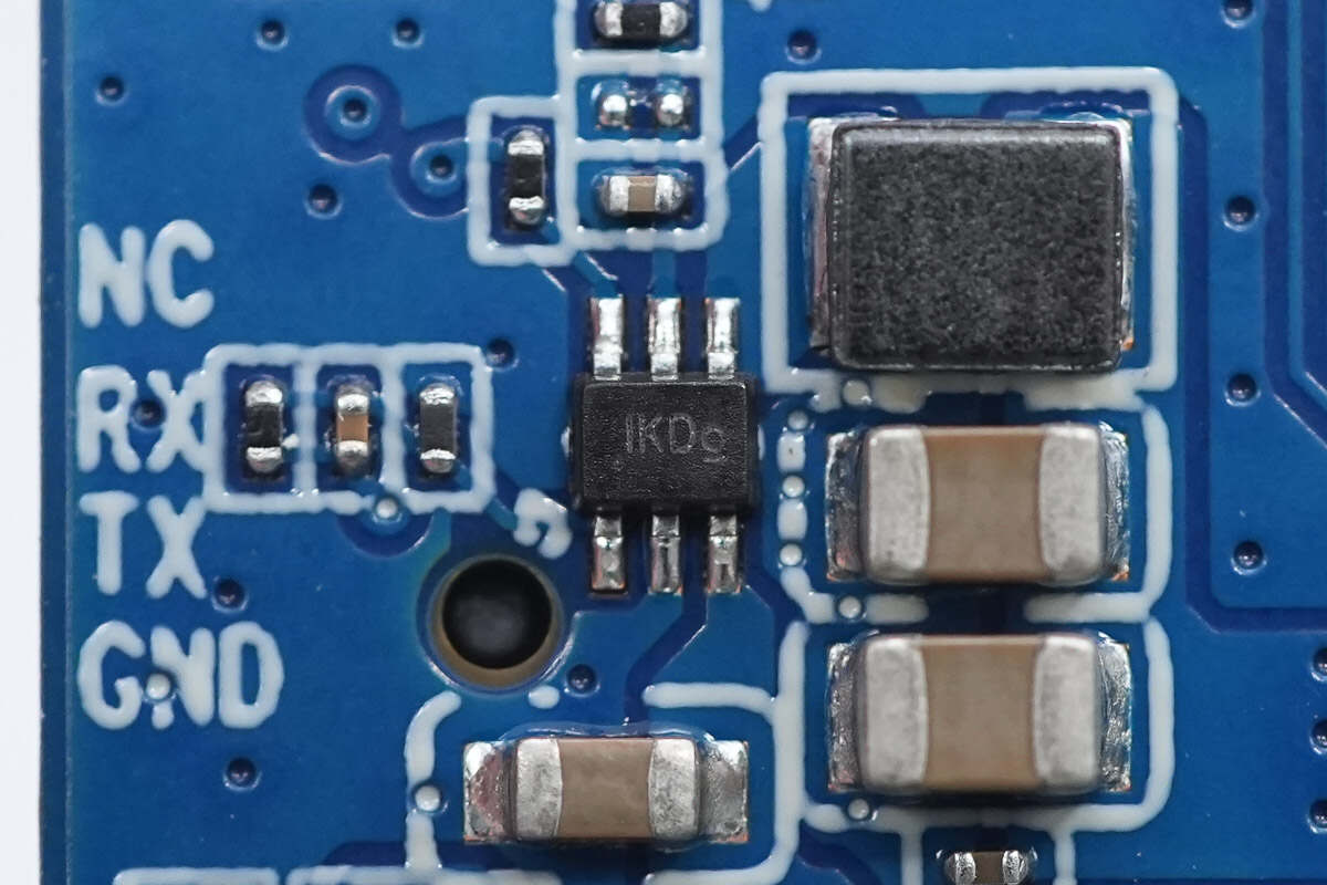
The synchronous buck converter chip is from ETA, marked with IK, model ETA3415. It integrates MOSFETs, supports a 7V input voltage, operates at a switching frequency of 3MHz, and supports a 1A output current. The chip includes short-circuit and overheat protection features and comes in a SOT563 package.
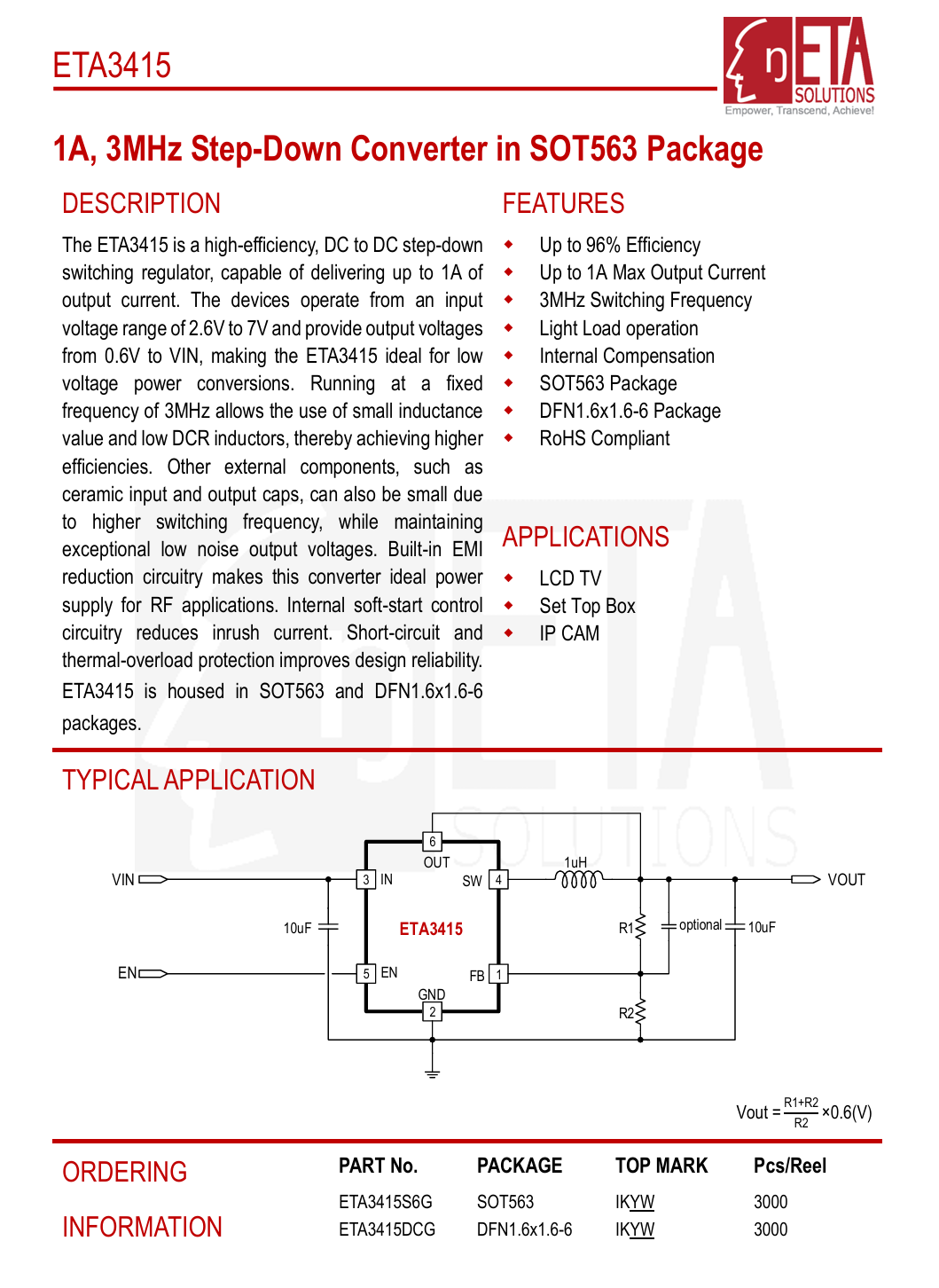
Here is the information about ETA ETA3415.
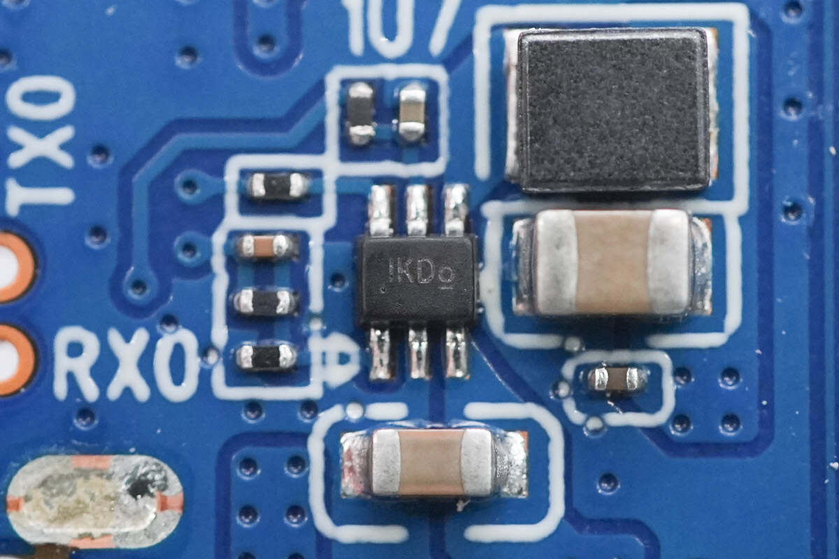
Close-up of the other ETA3415 synchronous buck converter chip.
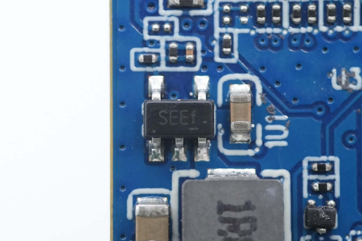
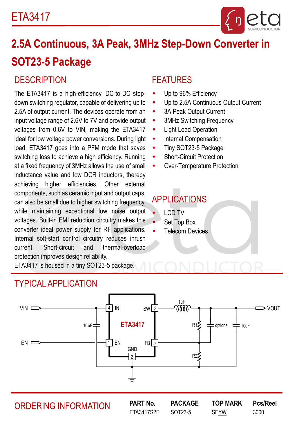
The synchronous buck converter chip is from ETA, marked with SE, model ETA3417. It integrates internal MOSFETs, supports 7V input voltage, operates at a switching frequency of 3MHz, and supports 2.5A continuous output current and 3A peak output current. It features soft-start, short-circuit protection, and overheat protection, and comes in a SOT23-5 package.
Here is the information about ETA ETA3417.
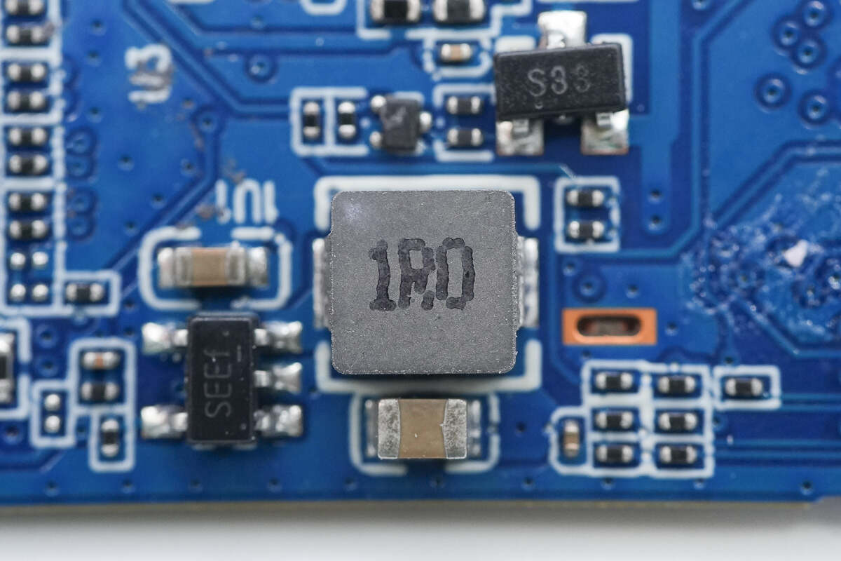
An external 1μH alloy inductor is paired with the chip.
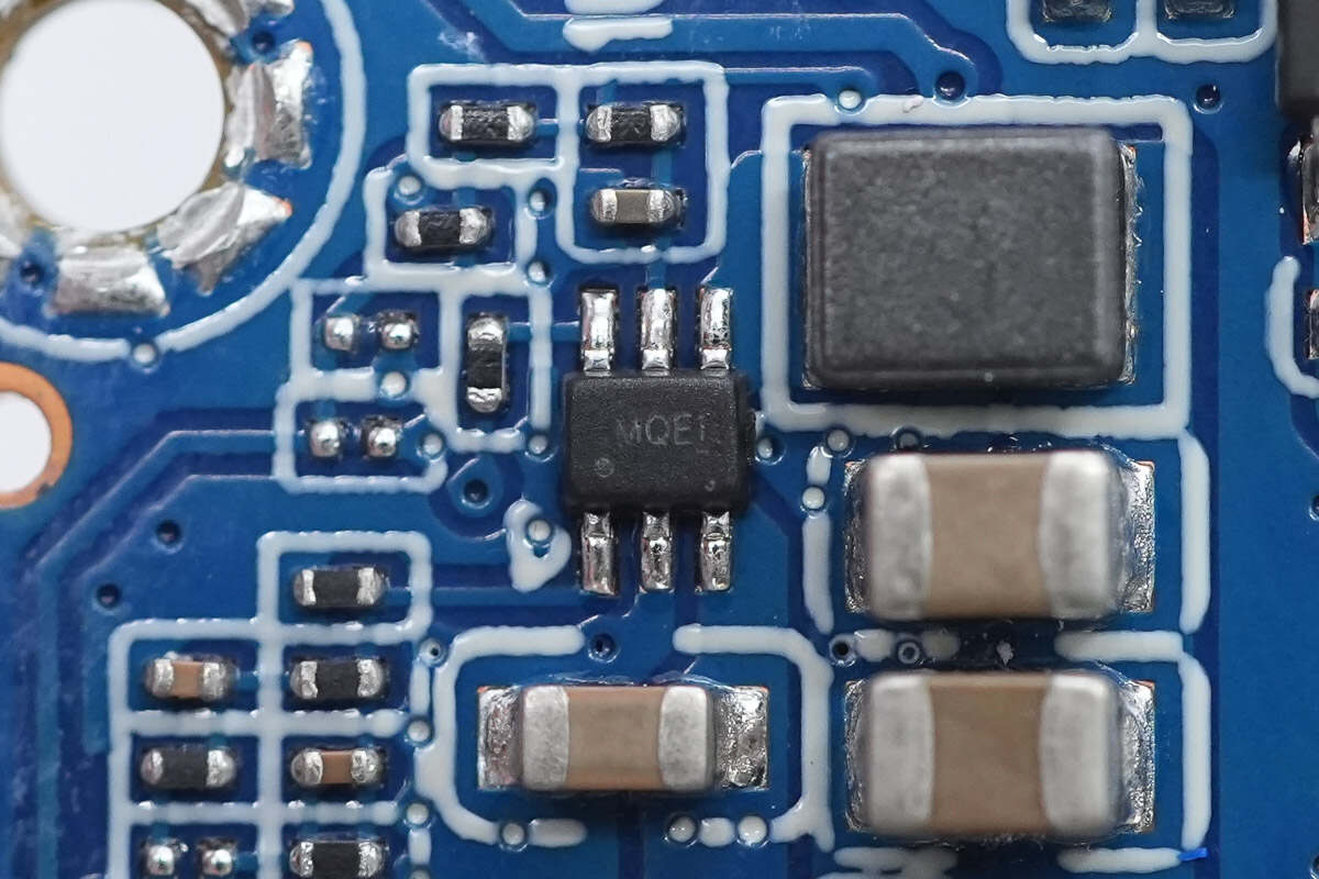
The synchronous buck converter chip is from ETA, marked with MQ, model ETA3512. It integrates internal MOSFETs, supports 5.5V input voltage, operates at a switching frequency of 2MHz, and supports 3A output current. The chip features cycle-by-cycle overcurrent protection, short-circuit protection, and overheat protection, and comes in a SOT563 package.
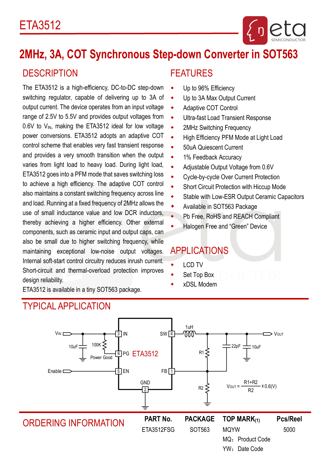
Here is the information about ETA ETA3512.
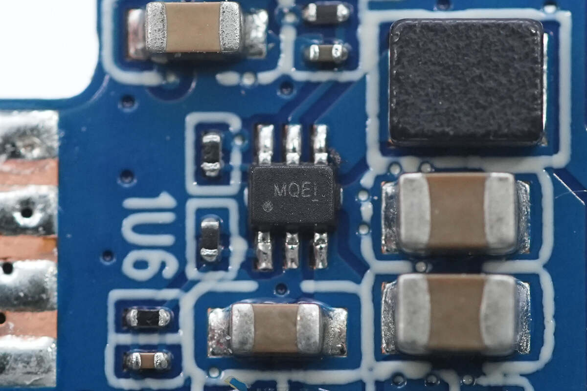
Close-up of the other ETA3512 synchronous buck converter chip.
A total of three ETA3512 synchronous buck converter chips are used.
The boost converter chip is from VOLTAIC, model VIS2007. It is a fully integrated synchronous boost converter with built-in 10/30mΩ MOSFETs, supports a 5V output voltage, and features an 8A peak switching current limit. It includes integrated compensation circuitry and soft-start, offers overcurrent and short-circuit protection, as well as output overvoltage protection and thermal shutdown. It comes in an FCQFN-10 package.
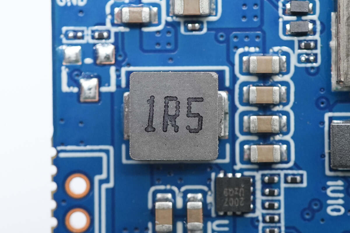
Close-up of the 1.5μH alloy boost inductor.
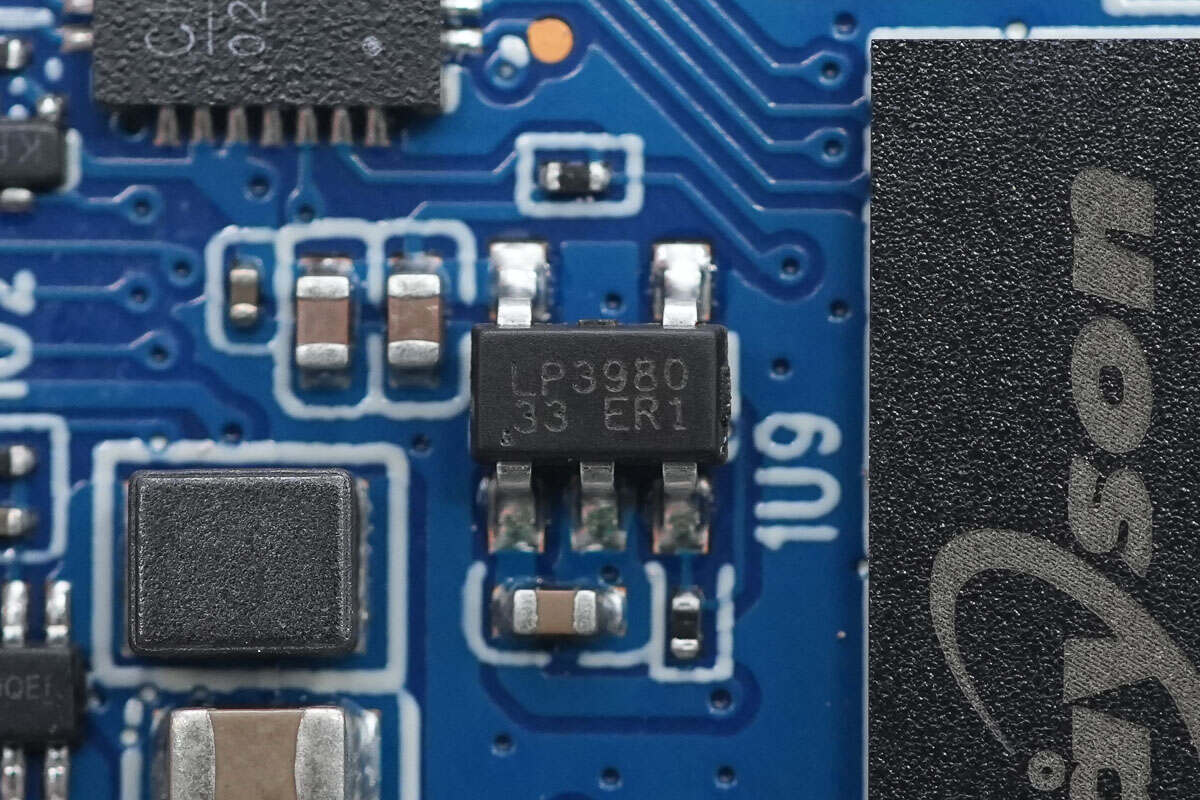
The voltage regulator chip is from LPS, model LP3980-33B5F. It supports a 5.5V input voltage, outputs 3.3V, delivers 500mA output current, and comes in a SOT23-5 package.
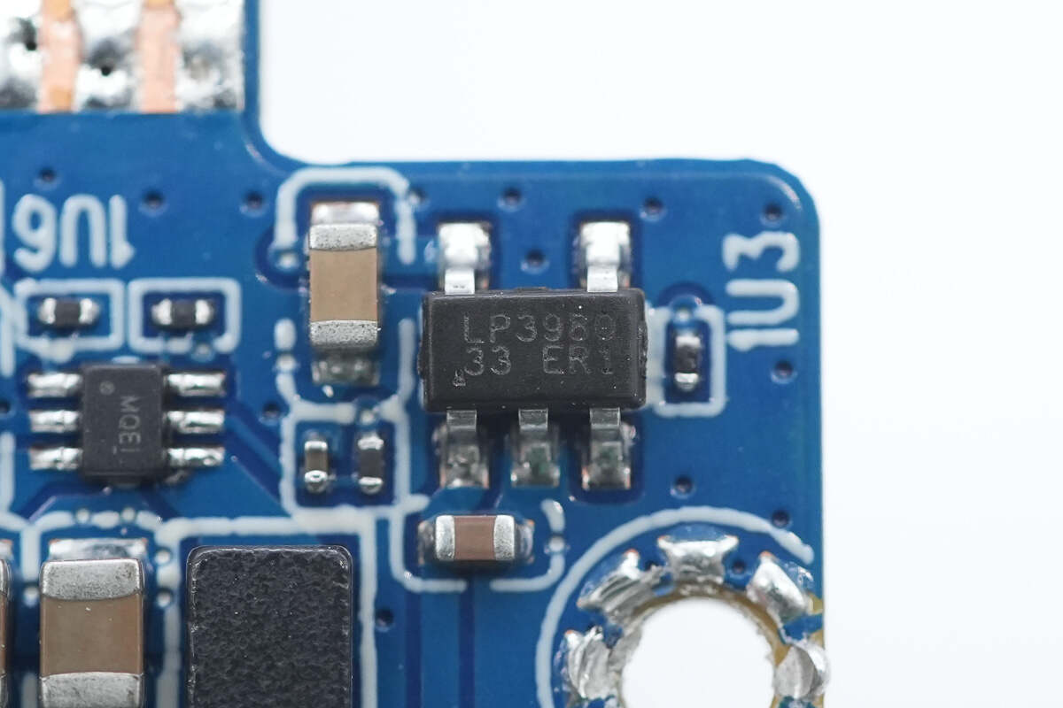
The other voltage regulator chip has the same model.
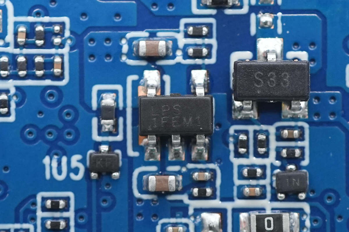
The voltage regulator chip is from LPS, marked with "LPS 1F," model LP3983HAB5F. It is an ultra-low noise regulator supporting a 6V input voltage, with adjustable output voltage and a 600mA output current. It comes in a SOT23-5 package.

The overcurrent protection chip is from LPS, marked with "LPS C0," model LPW5209AB5F. It supports a 6V input voltage, has a current limit of 2.1A configurable via an external resistor, and provides short-circuit and overheat protection. It comes in a SOT23-5 package.
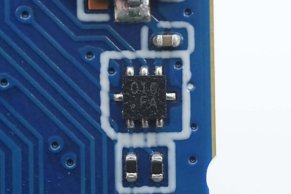
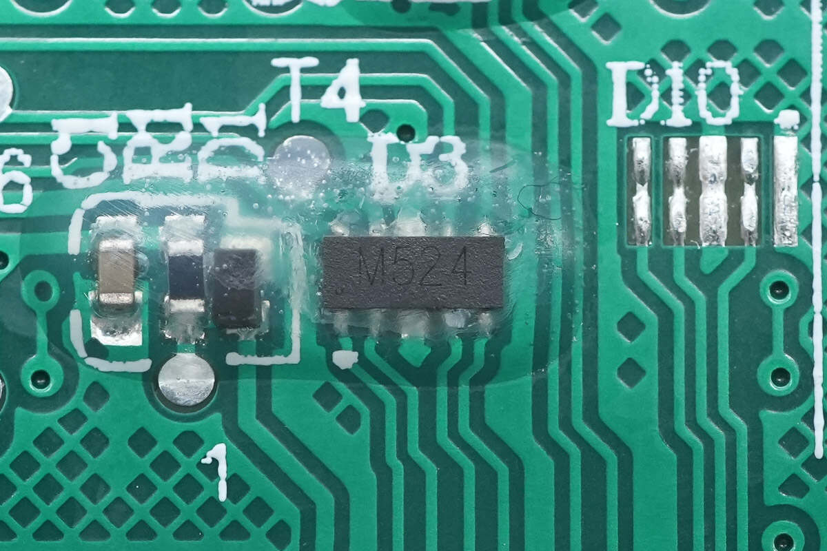
The LED driver chip is from Awinic, marked with "016," model AW2016QNR. It is a three-channel constant current LED driver with automatic charging indication. It supports four selectable maximum drive current levels, 16 levels of LED current configuration, and 4096 color mixing options. Communication is via the I2C interface, and it comes in a QFN-8L package.
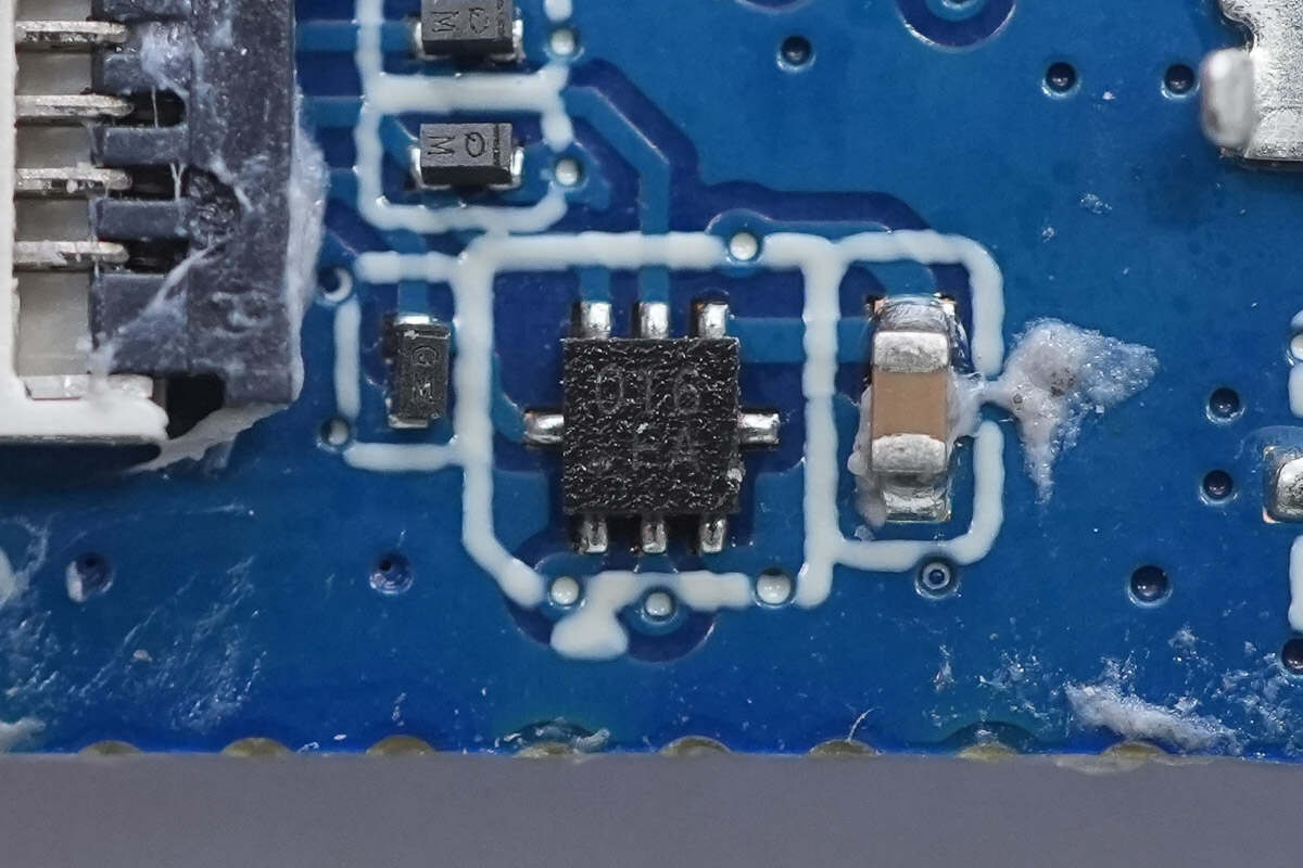
The other LED driver has the same model.
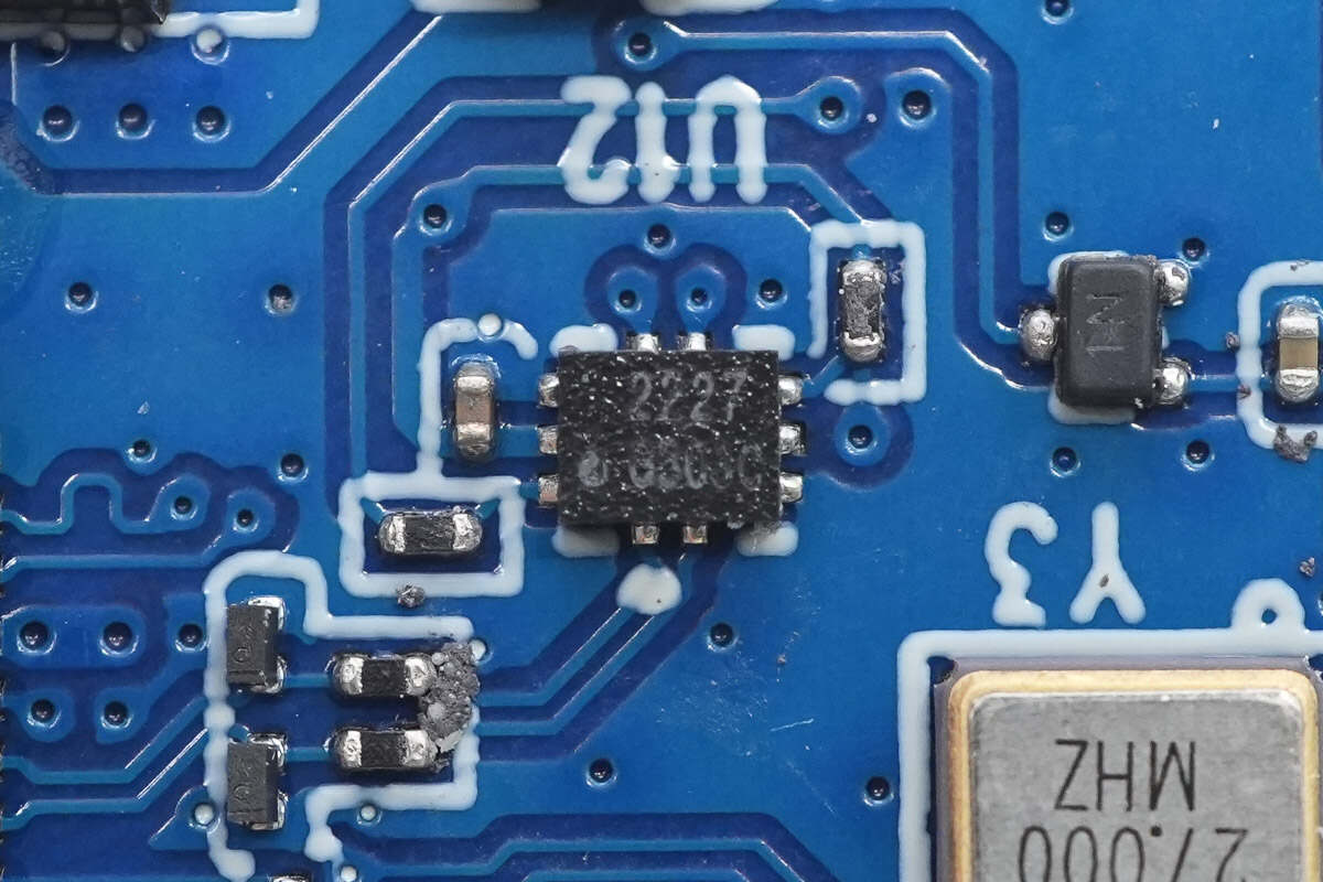
Close-up of the toggle switch marked with "2227."
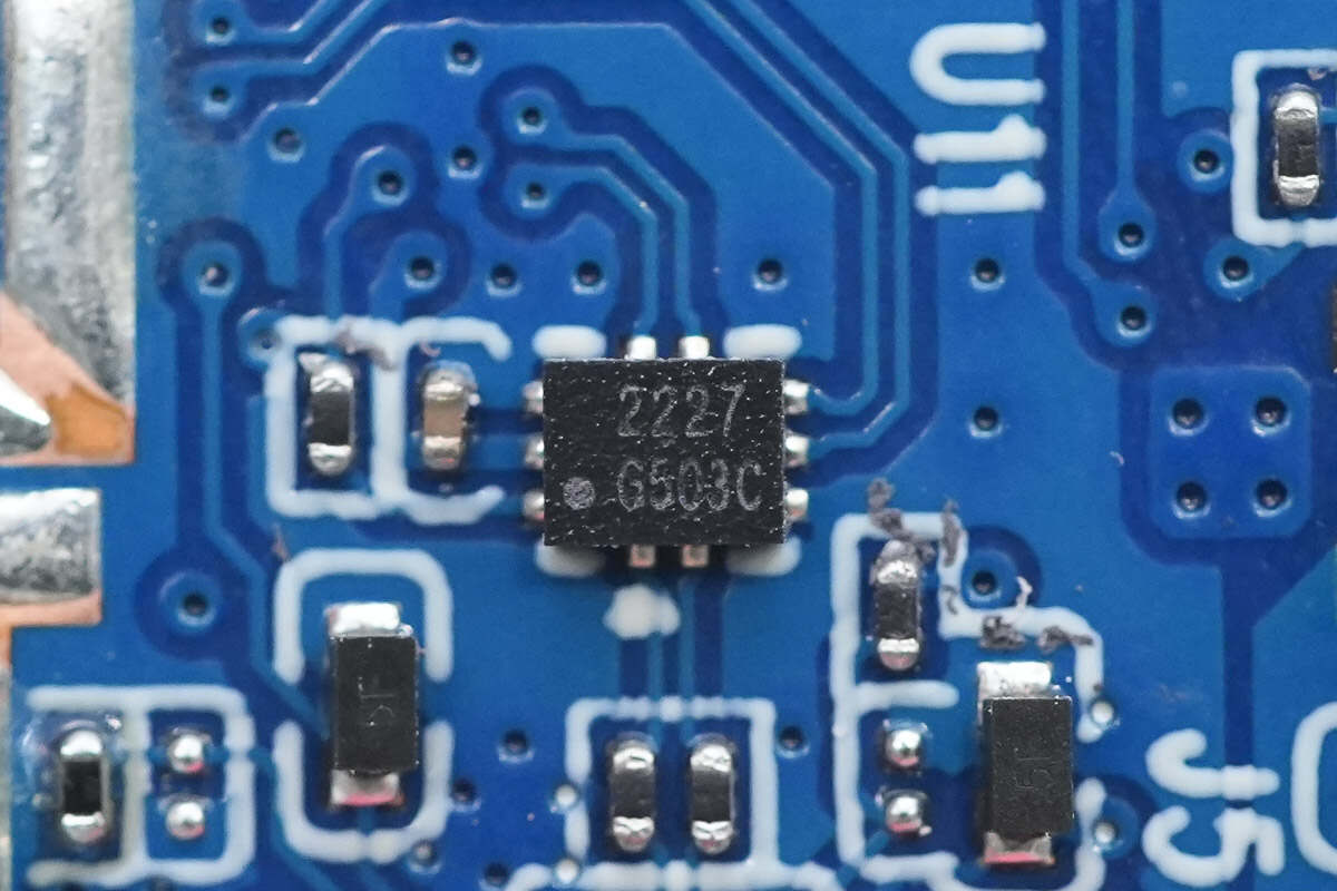
There are two toggle switches of the same model.
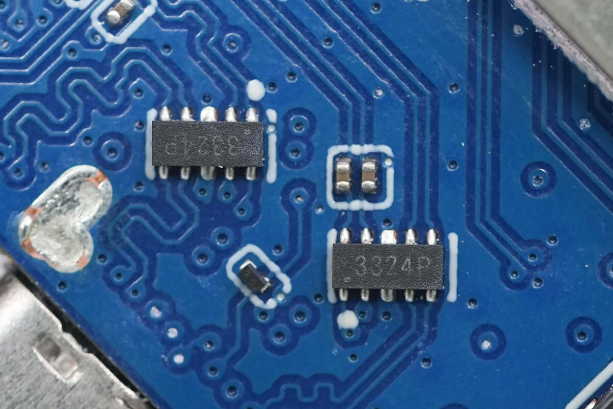
Two TVS arrays marked with "3324P" are used for electrostatic protection of the USB-C interface.
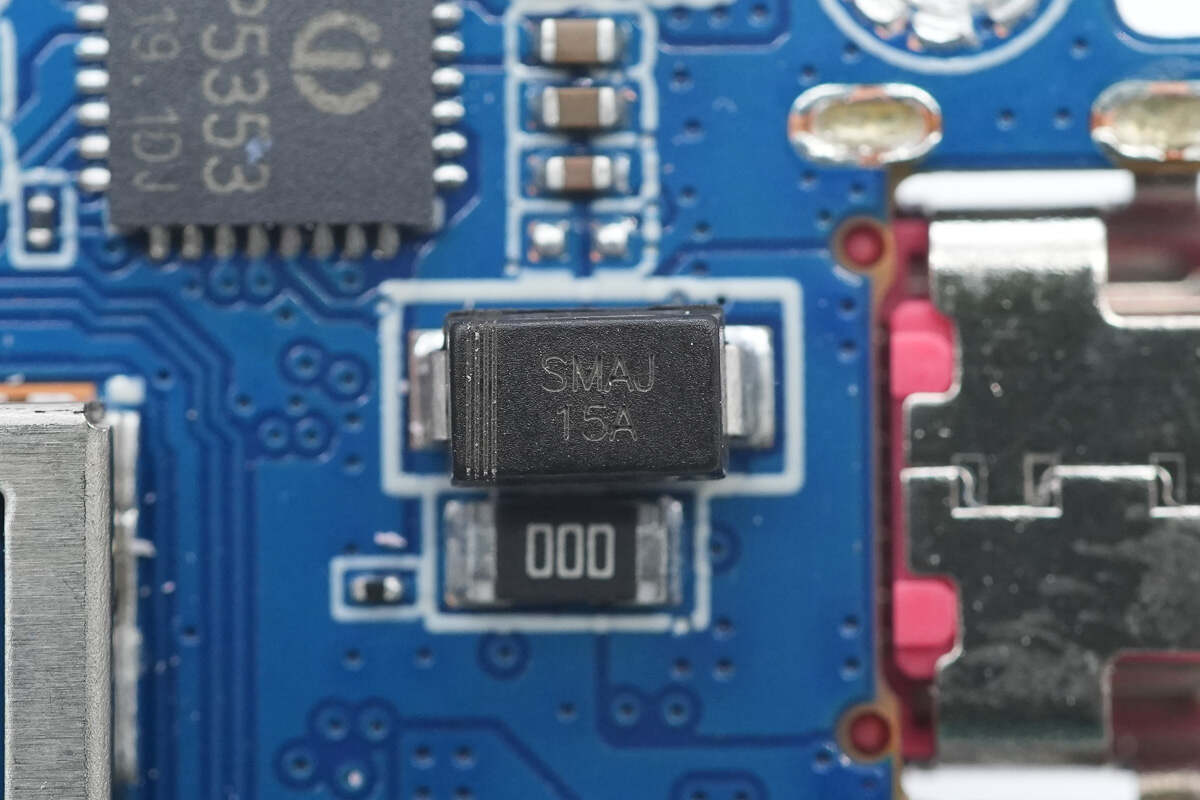
An SMAJ15A TVS diode is used for overvoltage protection on the USB-C interface.
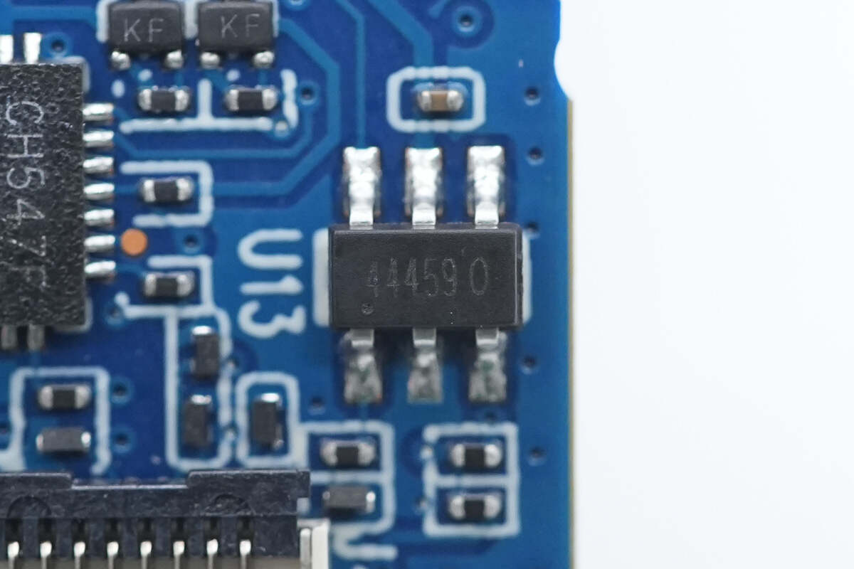
Close-up of the chip marked with "444590."
Close-up of the ribbon cable connector for the touch screen.
Close-up of the ribbon cable connector for the side buttons.
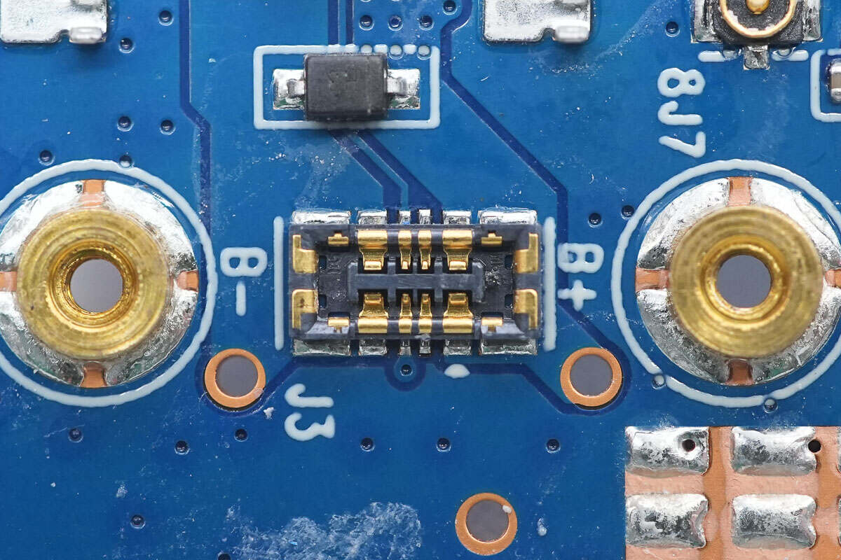
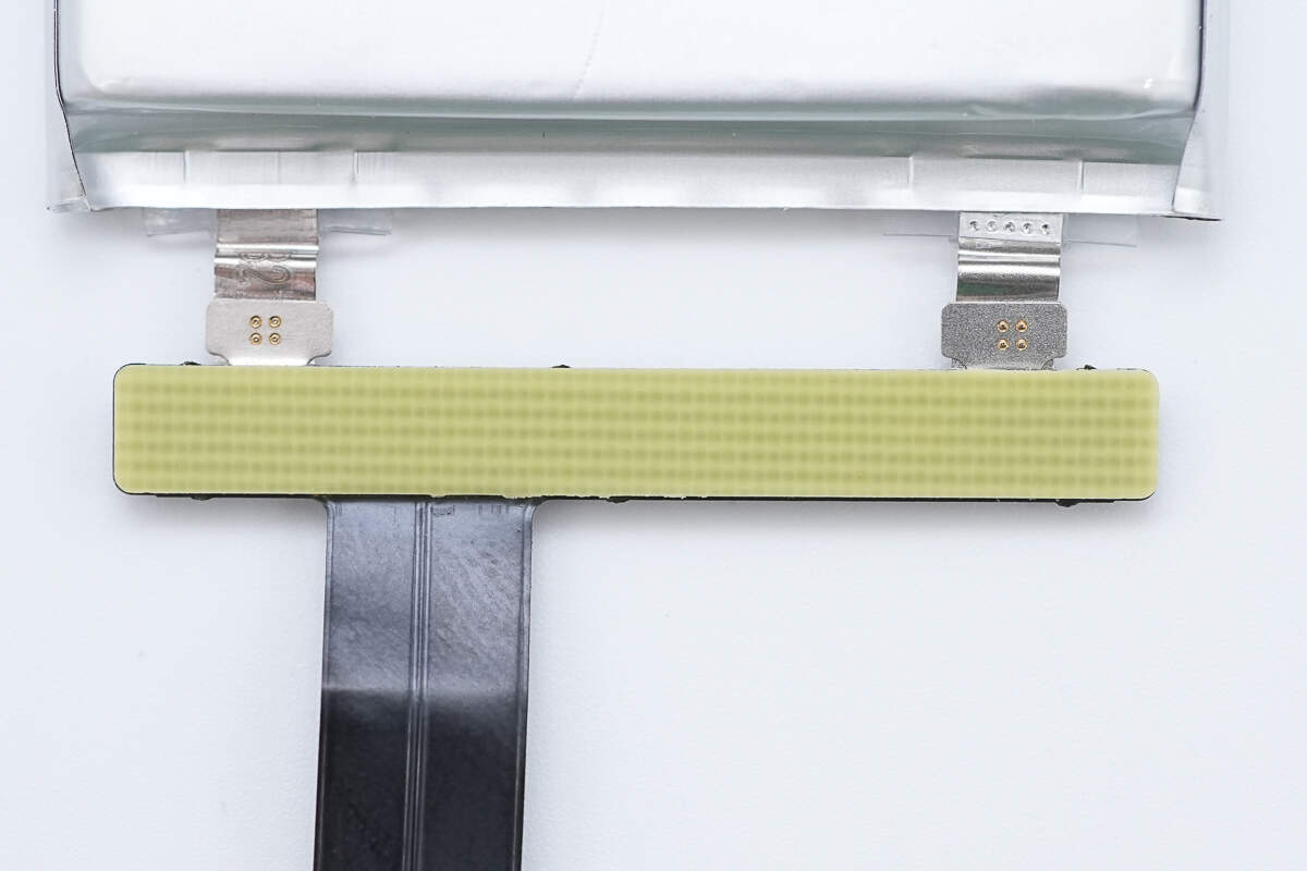
Close-up of the battery ribbon cable connector.
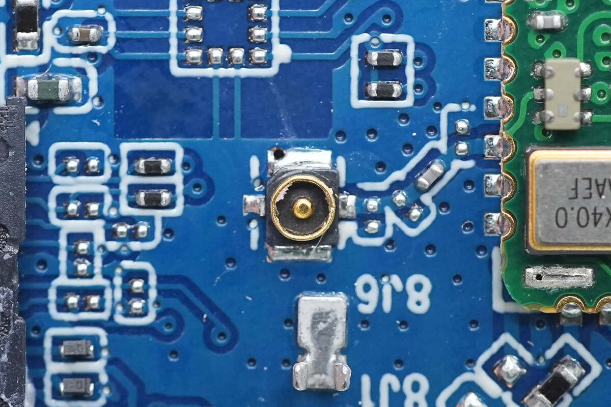
Close-up of the connector for the WiFi antenna.
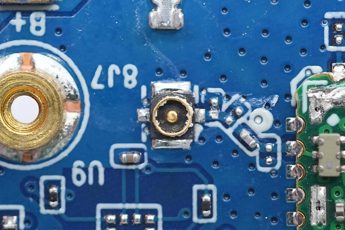
The other antenna connector is the same.
Close-up of the TF card slot.
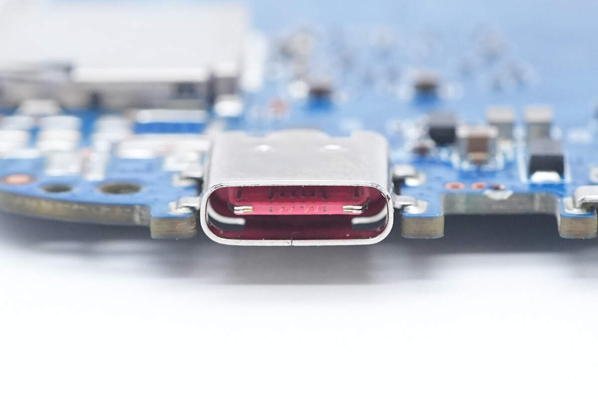
The USB-C connector for power input has a red plastic sheet.
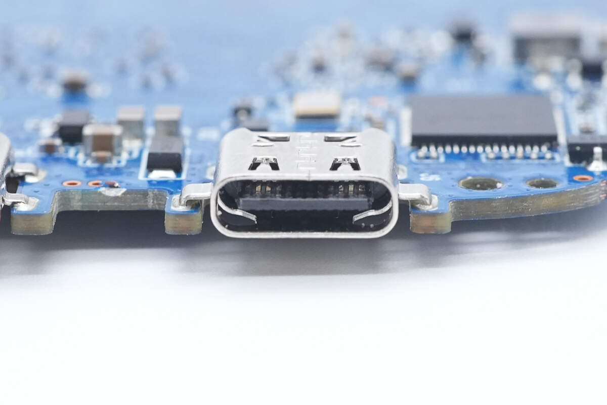
The USB-C connector for video output has a black plastic core.
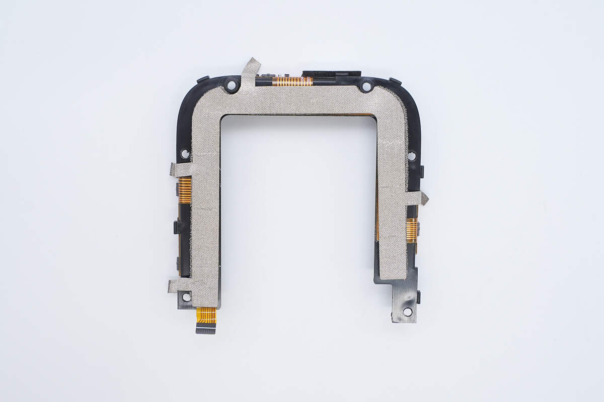
The bracket has ribbon cables attached for the buttons and indicator lights.
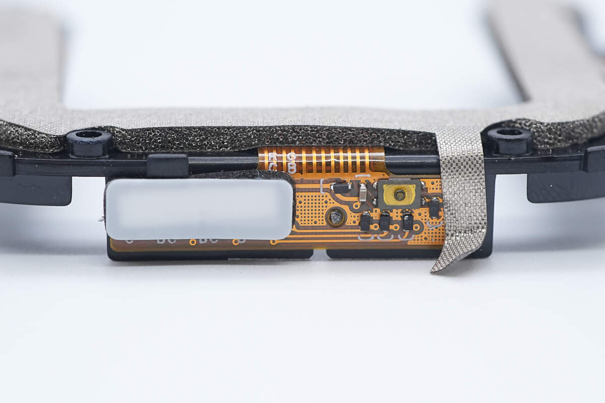
Close-up of the LED indicator lights and buttons.
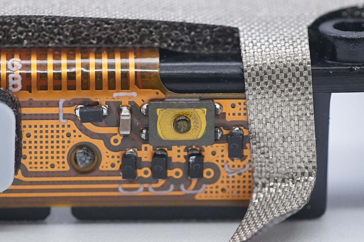
The buttons and LED indicator lights are protected by TVS diodes for electrostatic discharge protection.
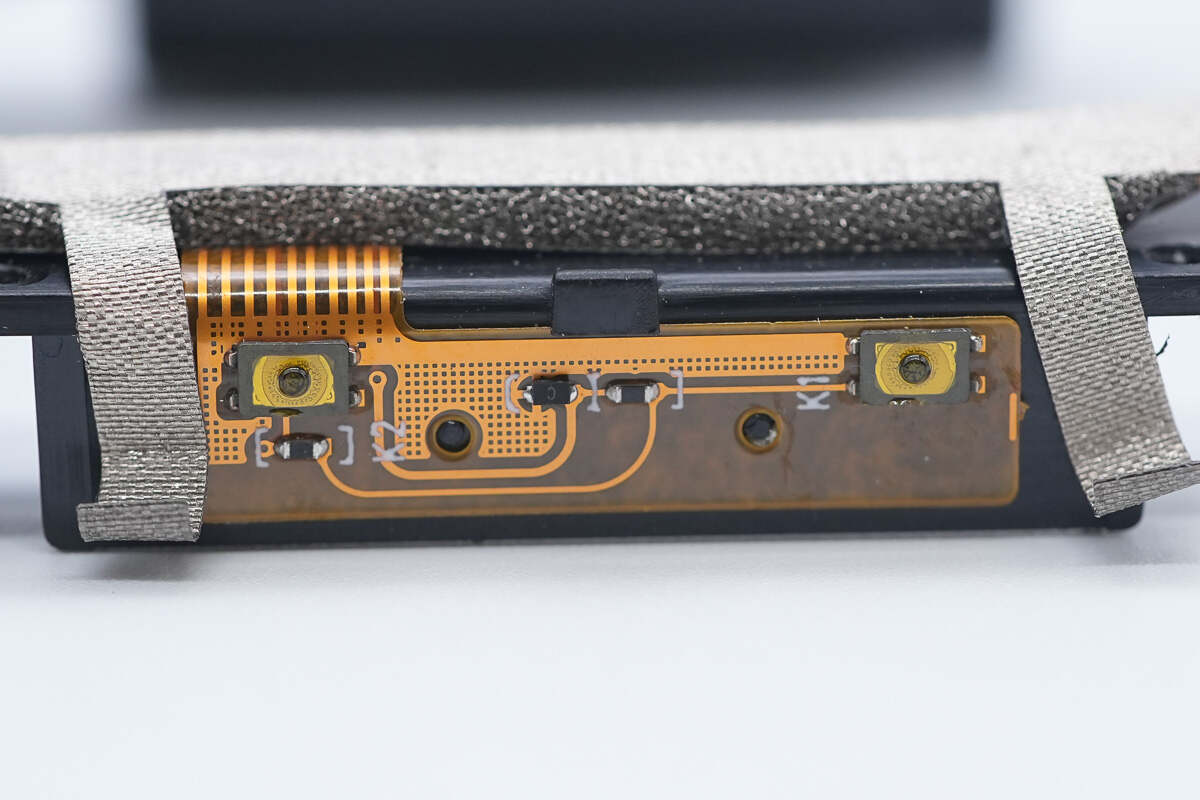
The volume up and down buttons are also protected by TVS diodes for electrostatic discharge protection.
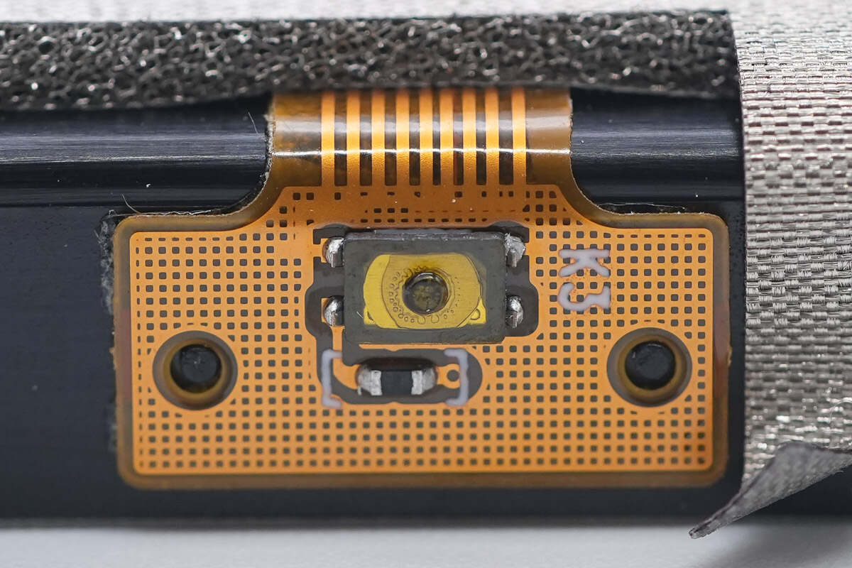
The shortcut key is also protected by TVS diodes for electrostatic discharge protection.
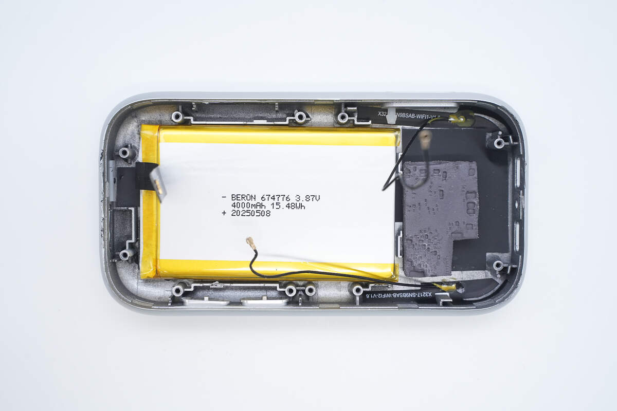
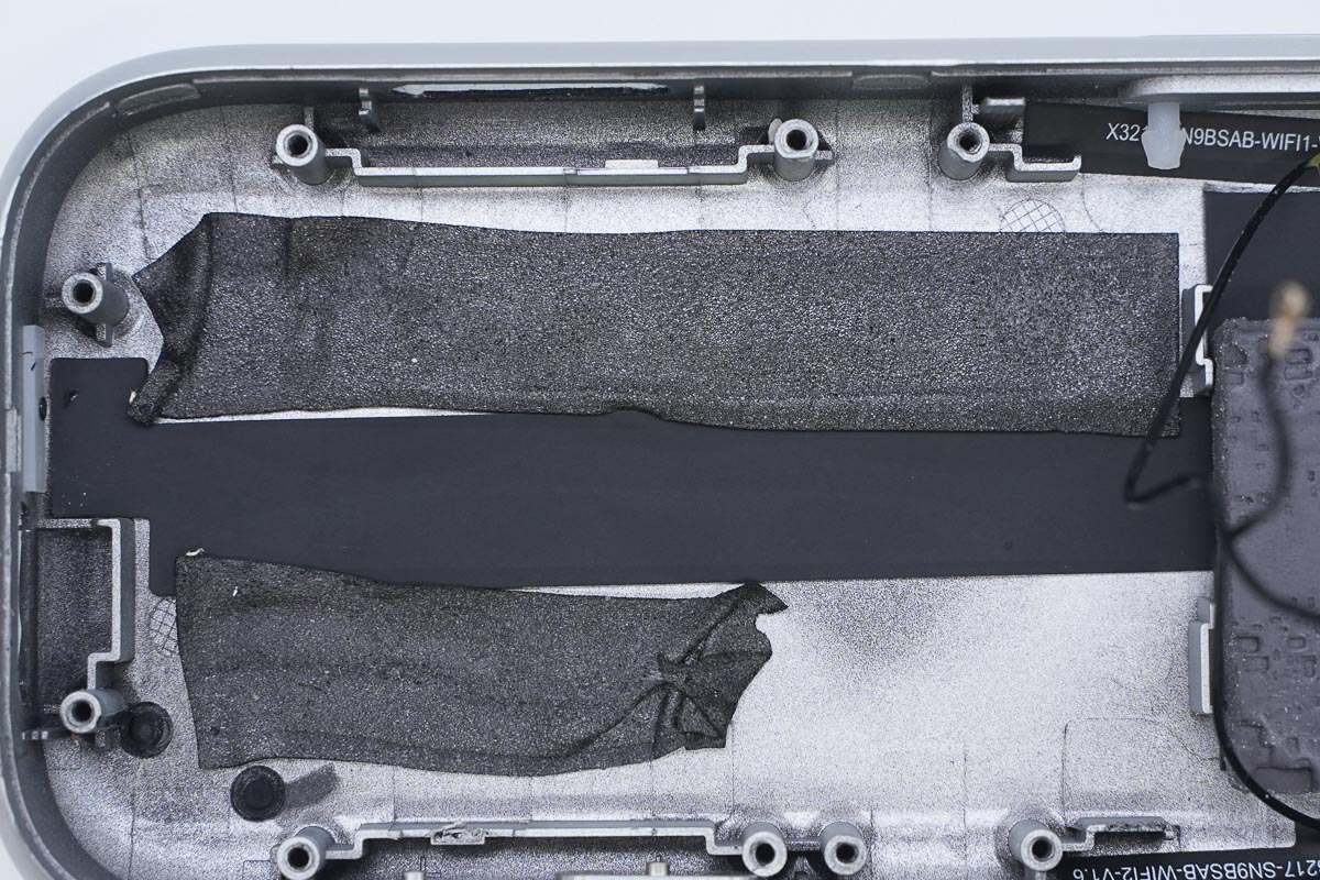
The interior of the casing contains the battery and thermal pads.
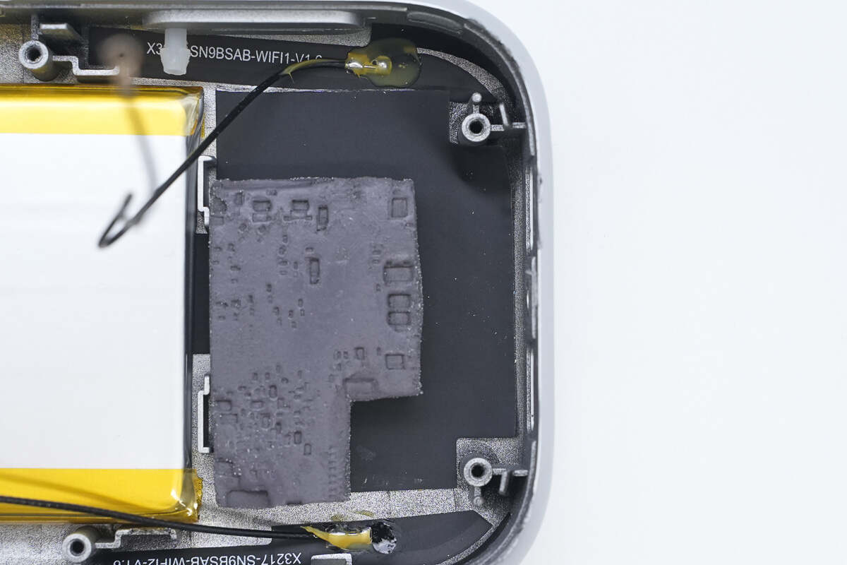
Beneath the thermal pad is a graphite thermal sticker, with WiFi antennas positioned on both the top and bottom sides.
Close-up of the WiFi antenna with a coaxial feeder cable soldered to it.
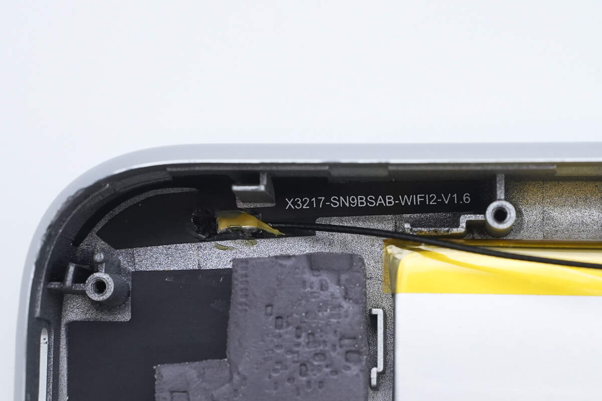
Close-up of the other antenna.
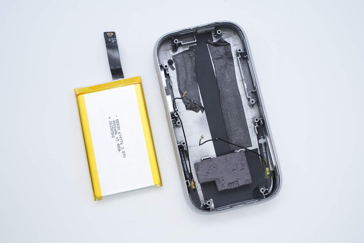
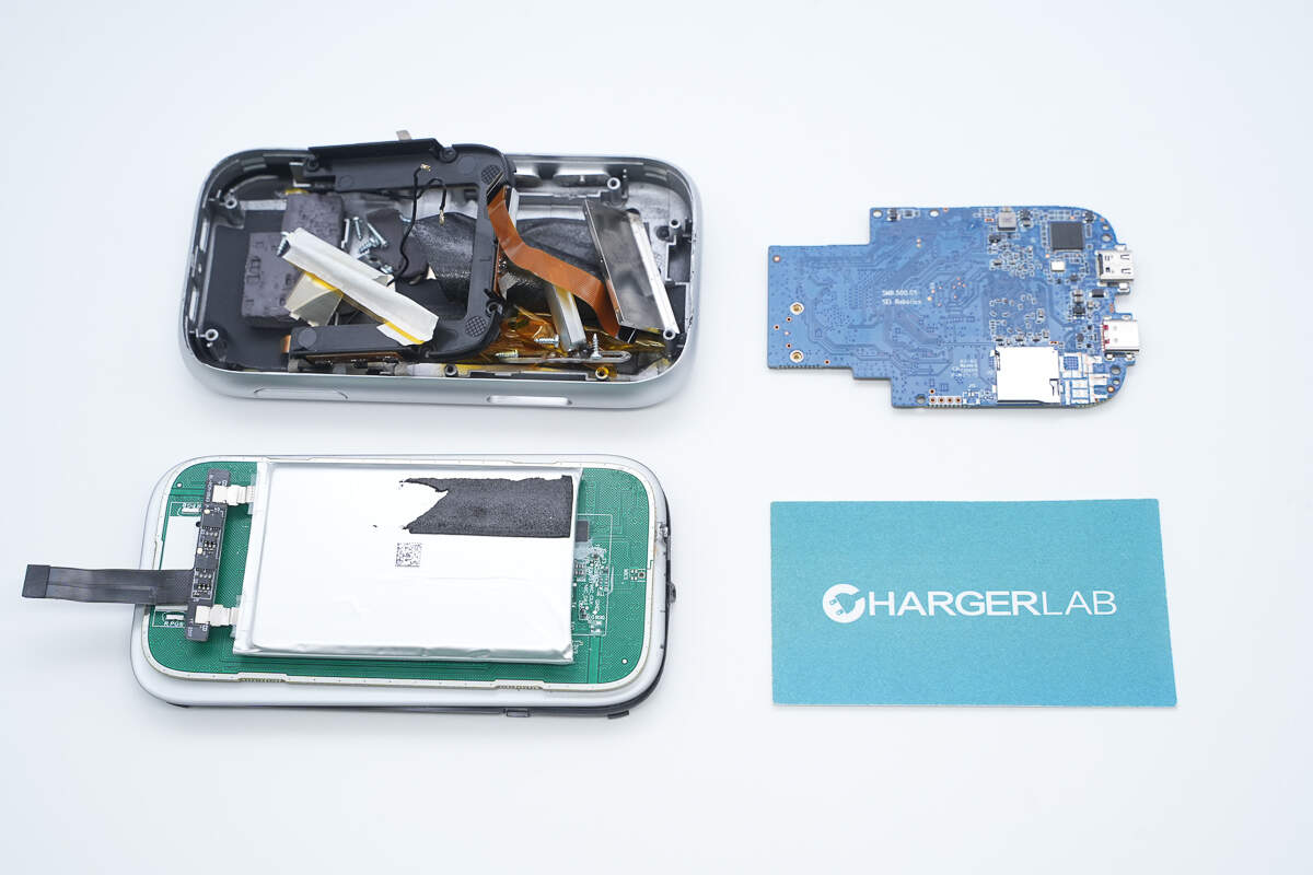
Removing the battery from inside the casing.
The battery is secured with double-sided adhesive, and graphite thermal stickers are applied inside the casing.
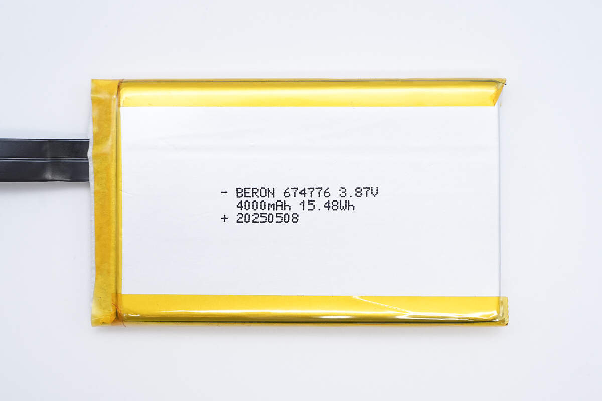
The battery is from BERON, model 674776, with a nominal voltage of 3.87V, capacity of 4000mAh, and energy of 15.48Wh.
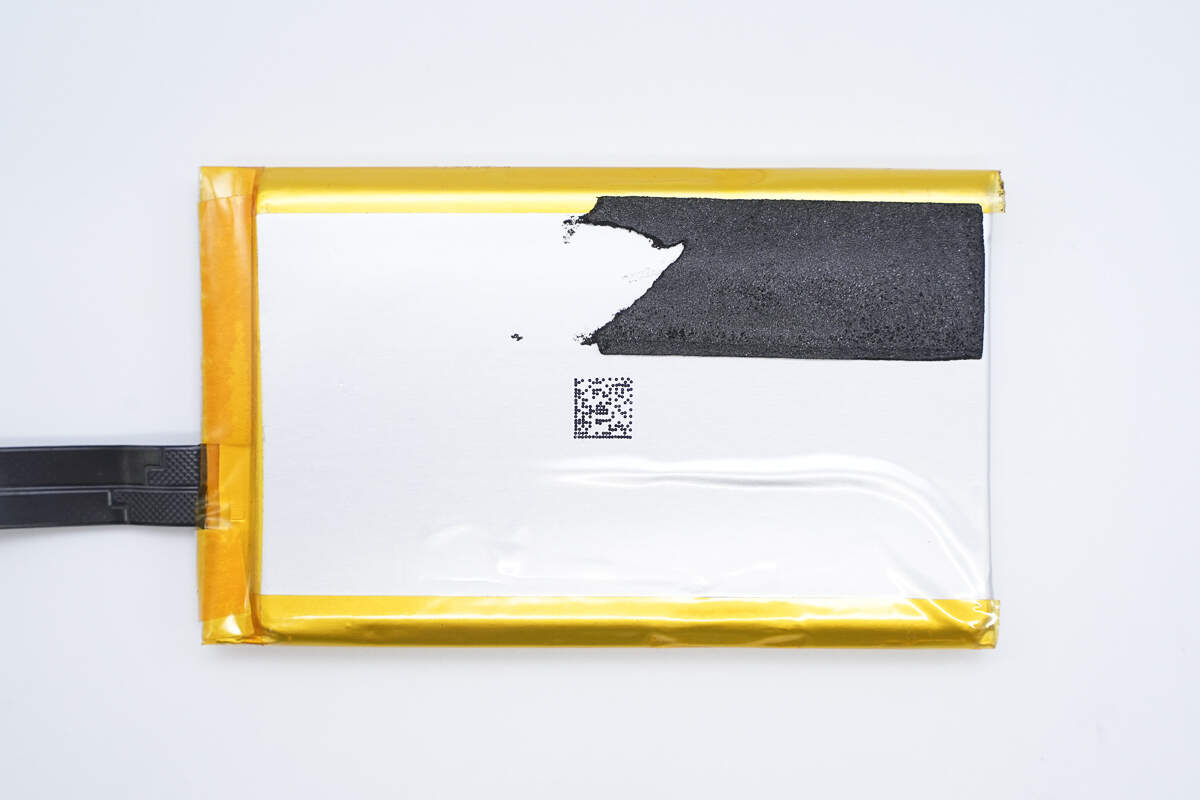
The back of the battery is printed with a QR code.
The front end of the battery is equipped with a protection PCB.

The battery protection PCB contains a protection chip and battery protection MOSFETs.
There are no components on the back side.
The battery tabs are connected by spot welding.
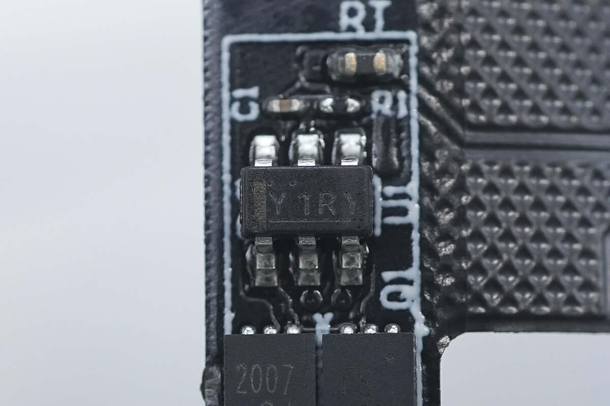
The battery protection chip is marked with "Y1RY," and there is a thermistor located at the upper right.
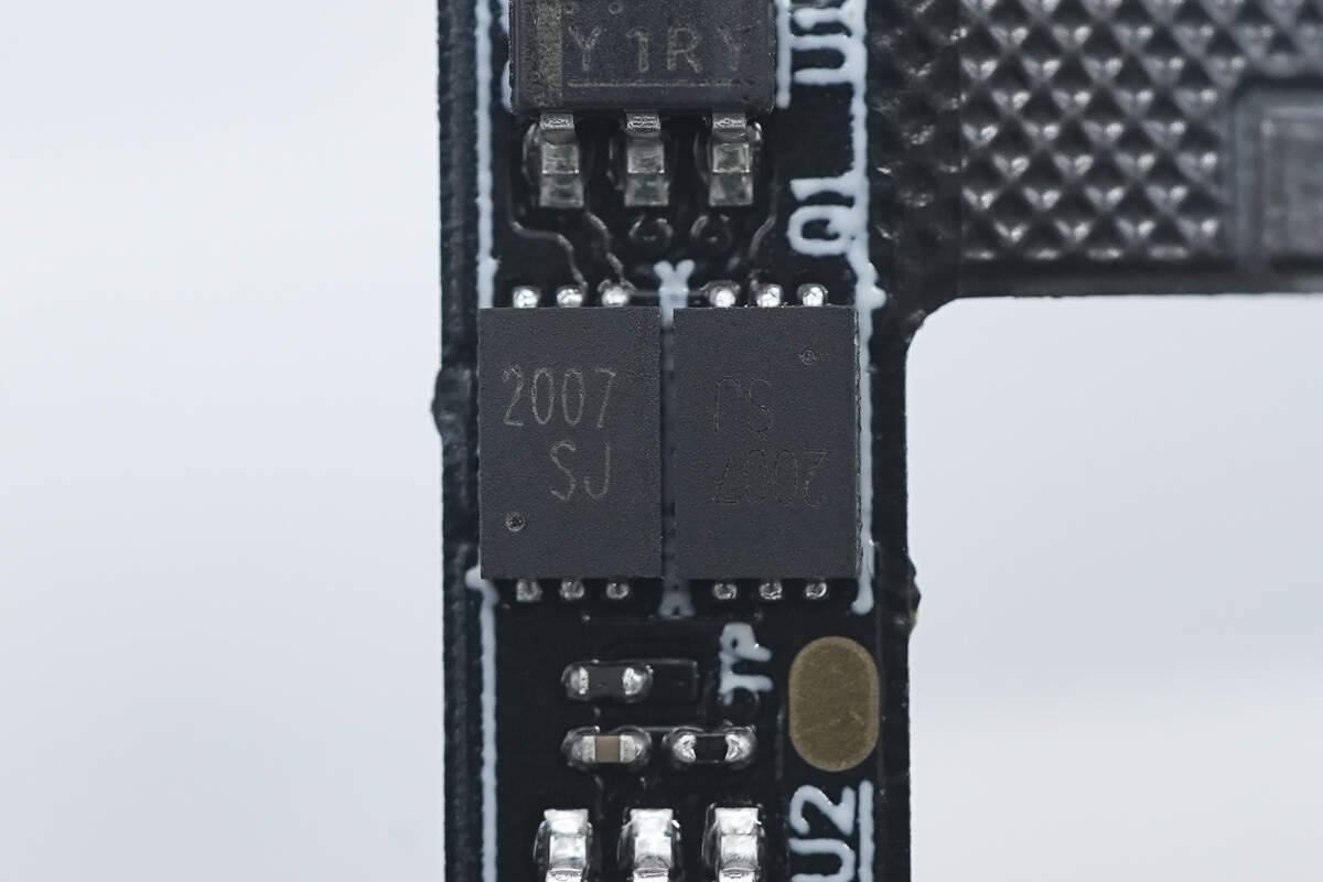
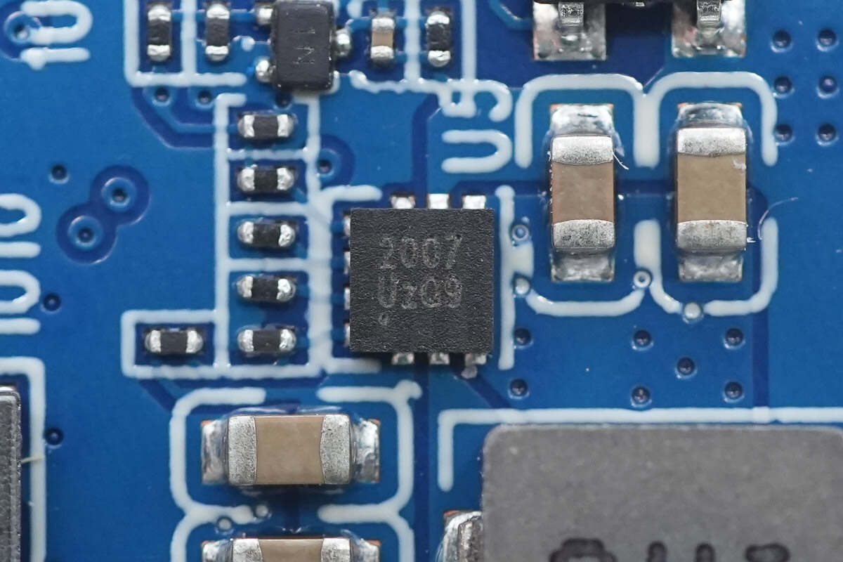
There are two battery protection MOSFETs marked "2007." The protection PCB includes two identical protection circuits; to save space, further details are omitted.
Well, those are all components of the RayNeo Magic Box 2 for AR Glasses.
Summary of ChargerLAB
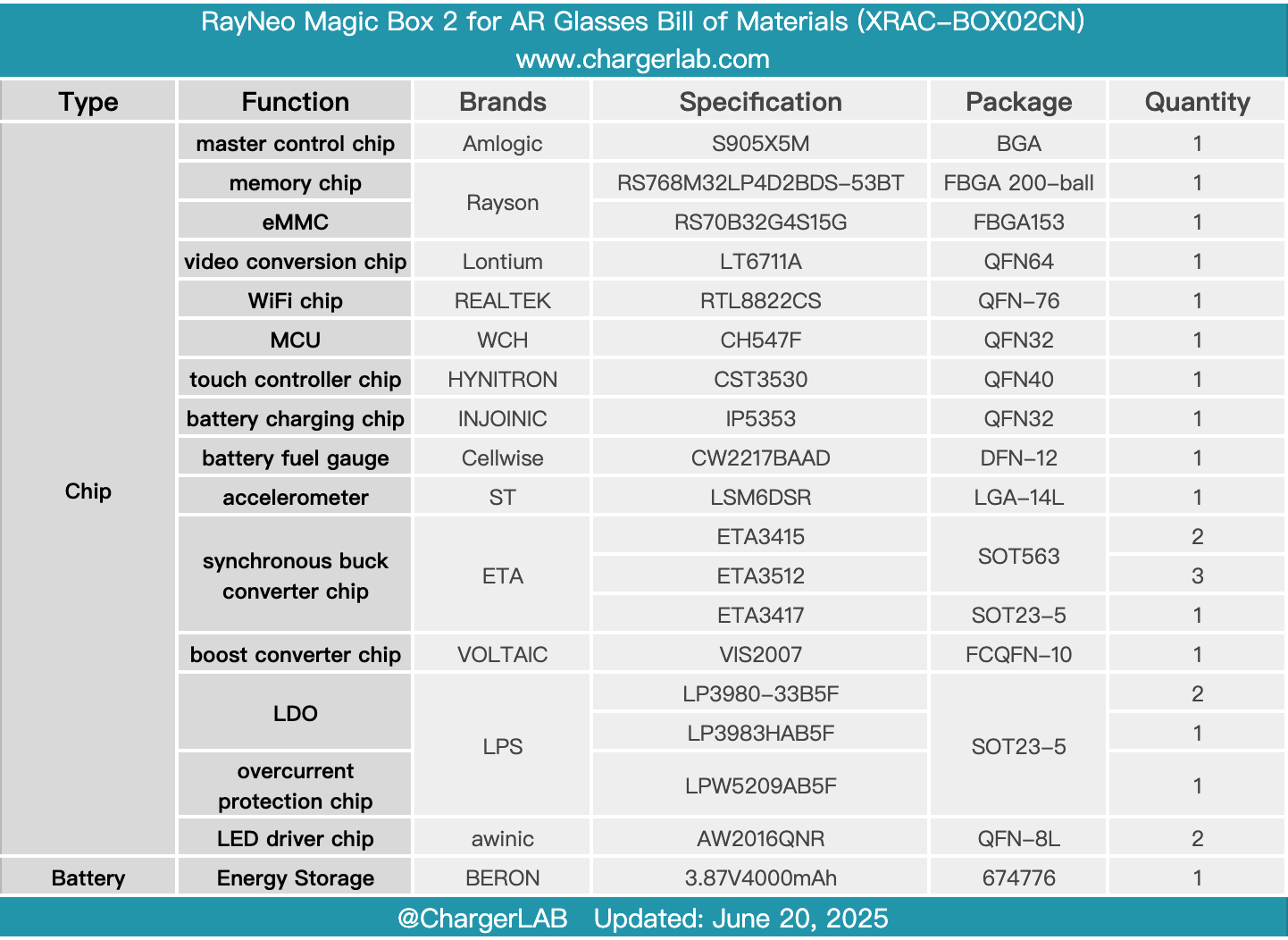
Here is the component list of the RayNeo Magic Box 2 for AR Glasses for your convenience.
The RayNeo Magic Box 2 is a multifunctional device that can connect directly to RayNeo glasses via a USB-C interface for an immersive, large-screen viewing experience. It supports video playback, screen casting, and NAS connection, delivering ultra-high-definition audio and video output while being compatible with various wireless protocols. The device features a large touch panel on the side for easy everyday use and includes a built-in battery that supports up to 4 hours of continuous video playback.
After taking it apart, we found it uses a HYNITRON touch chip. The PCBA module features a shielding cover and is equipped with an Amlogic S905X5M master control chip paired with Rayson LPDDR4X memory and eMMC storage. It also uses a Lontium video conversion chip for DisplayPort output.
The battery charging chip is from Injoinic, with power measurement handled by a Cellwise fuel gauge. Synchronous buck converters come from ETA, and the LDO regulators are from LPS. The WiFi module is supplied by eardatek. The PCBA is coated with thermal gel and equipped with thermal pads to enhance heat dissipation. Additionally, graphite thermal stickers are applied inside the casing to reduce temperature rise and improve the user experience.
Related Articles:
1. Teardown of TECNO 45W Accessories Charger (U450TEC)
2. Teardown of Insta360 X5 Utility Fast Charge Case (CINSBAHM)
3. Teardown of Zhizu 2700Wh Zhiba MAX LiFePO₄ Swappable Battery Pack (DM60N-45ET)