Introduction
This teardown covers the NIU 280W electric bicycle charger. The charger features reverse-polarity protection on the output side and supports communication between the charger and the battery pack. Charging can only begin after mutual verification and coordination of technical parameters between the charger and the battery pack, ensuring safe operation.
The charger adopts a fixed-cable design, equipped with a 1.6-meter input cable and a 1-meter output cable. An indicator light is provided to display the charging status. Inside, a cooling fan is used to enhance airflow and dissipate the heat generated during charging. The following provides a closer look at this product.
Product Appearance
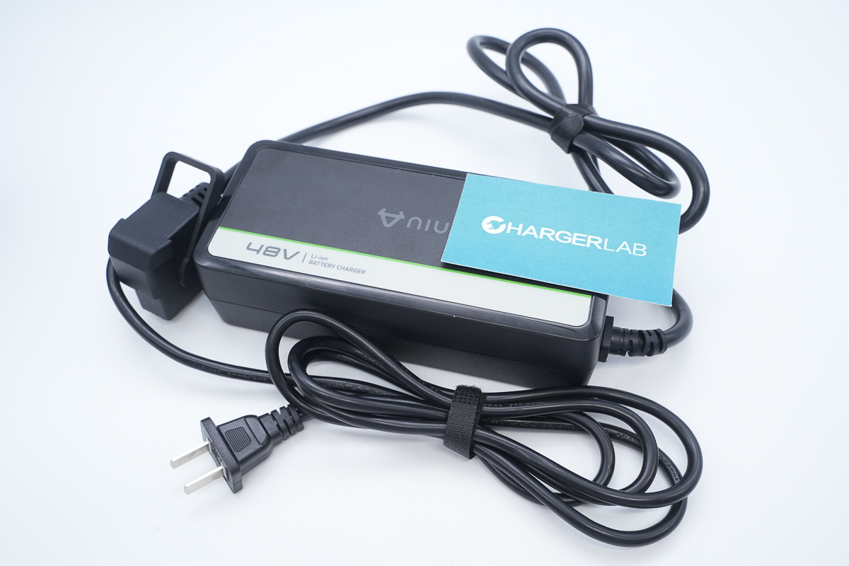
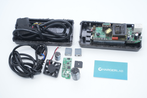
It adopts an integrated cable design.
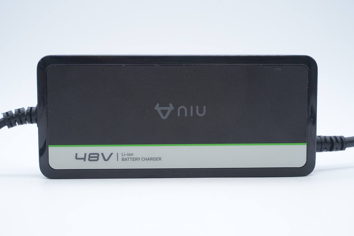
The front is printed with the NIU logo and “48V,” with a charging indicator located in the upper-right corner.
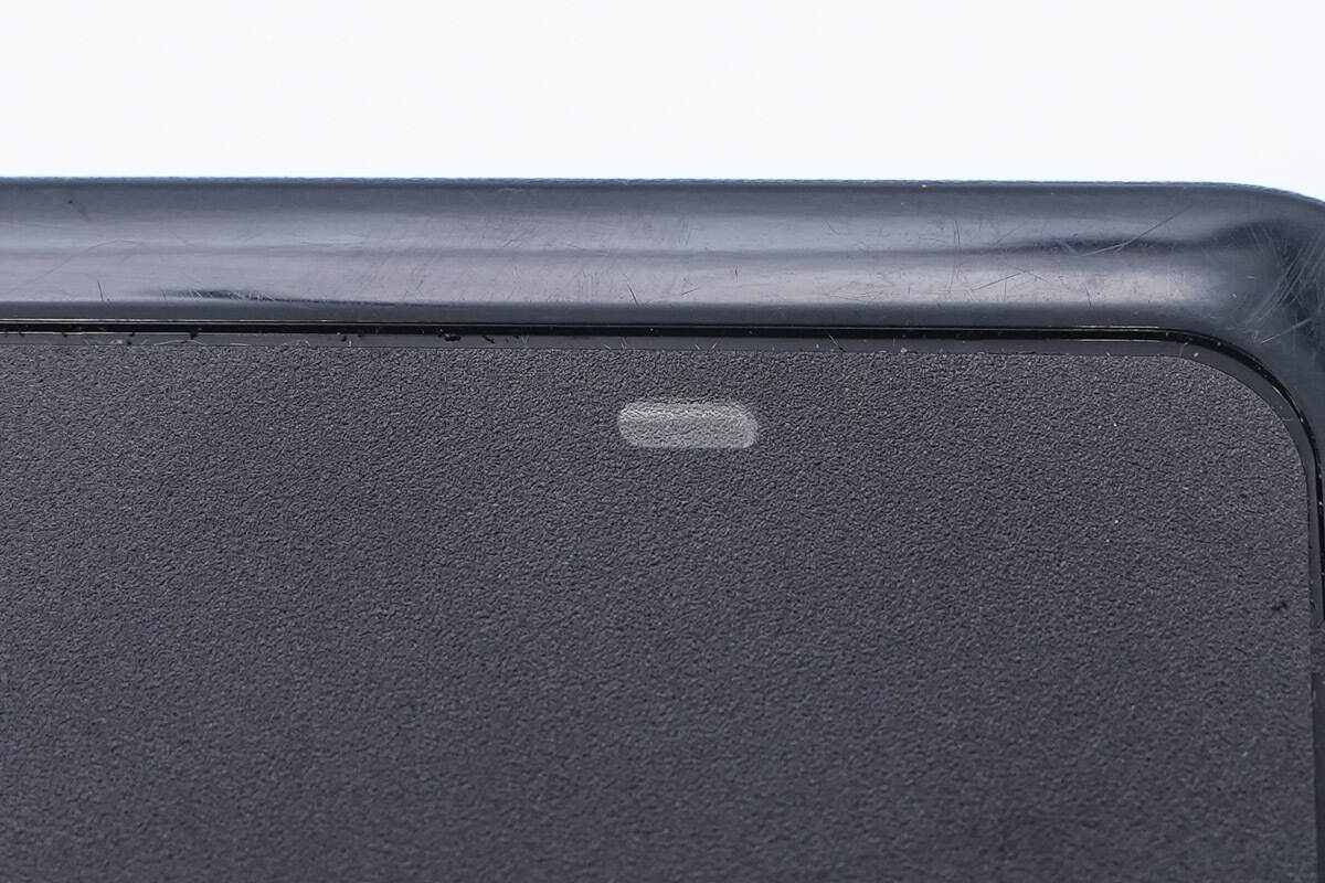
Close-up of the LED indicator.
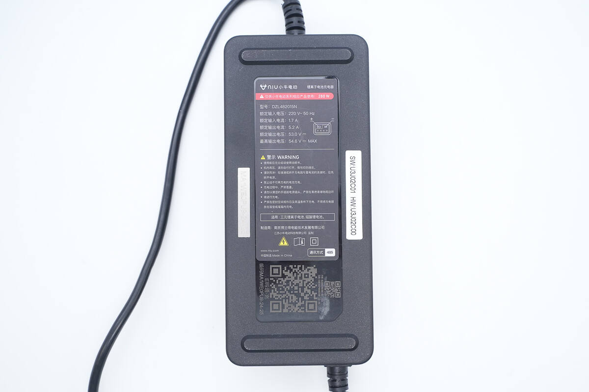
A nameplate is attached to the bottom, with anti-slip pads on both the upper and lower sides. On the left side of the nameplate is a permanent high-temperature-resistant label, while the label on the right indicates the charger’s hardware and software versions.
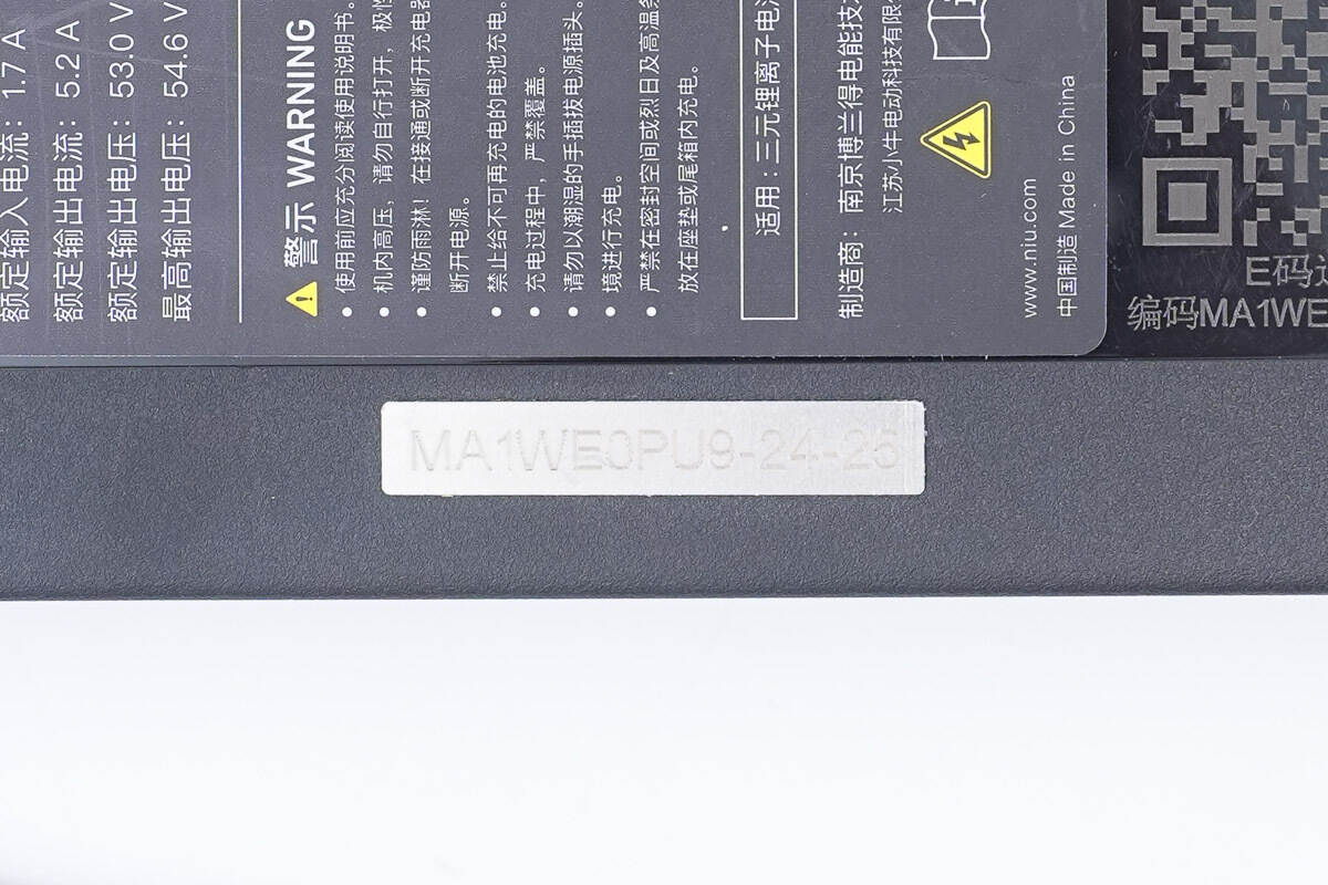
The permanent high-temperature-resistant label is marked MA1WE0PU9-24-25.
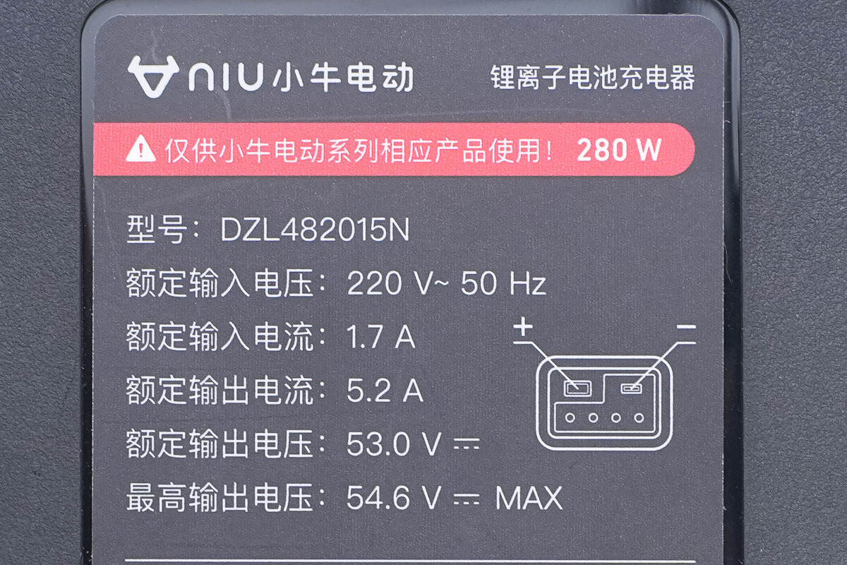
Model: DZL482015N
Rated input voltage: 220V~50Hz
Rated input current: 1.7A
Rated output current: 5.2A
Rated output voltage: 53.0V ⎓
Maximum output voltage: 54.6V ⎓ MAX
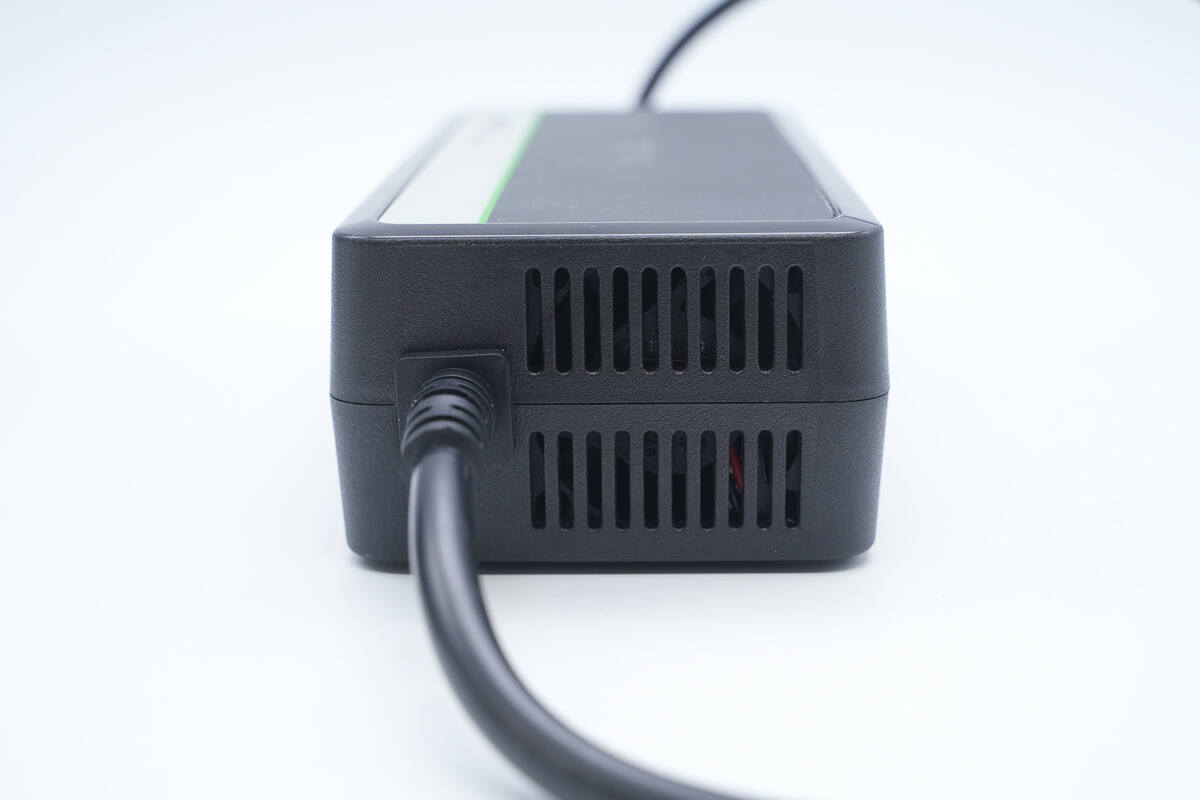
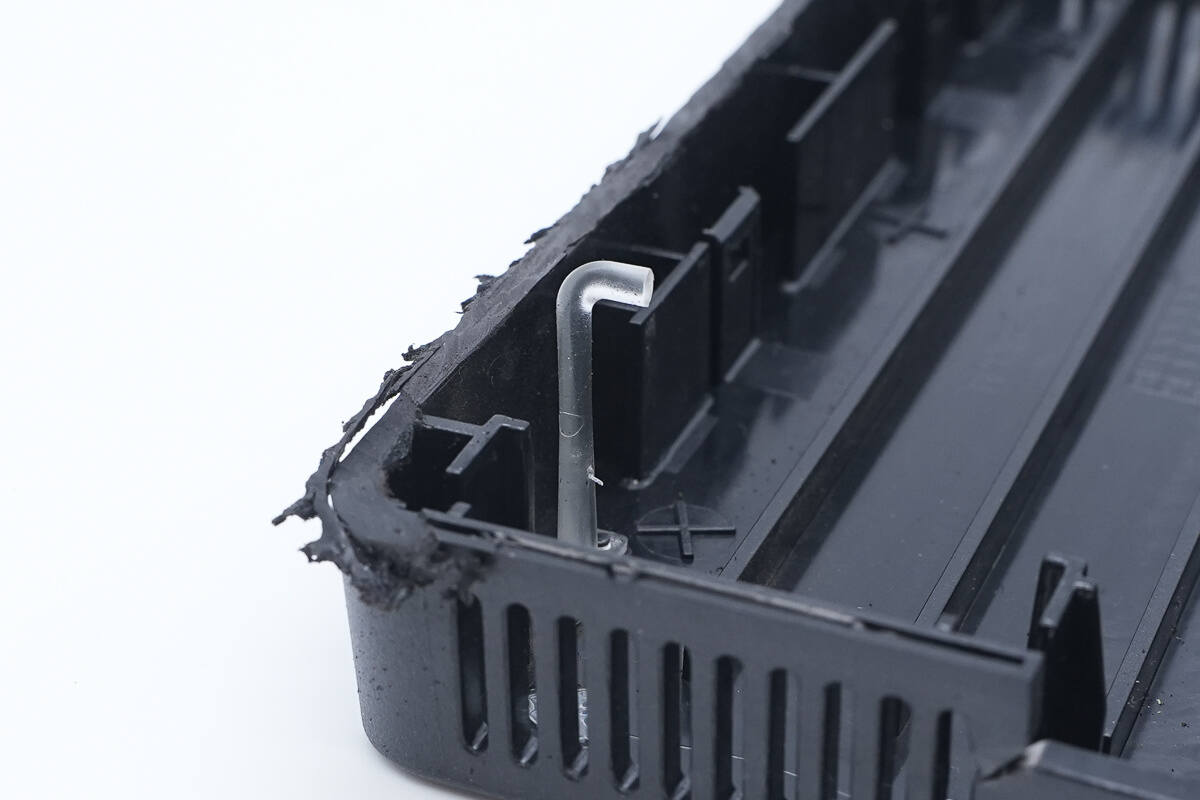
The AC input side is equipped with a cooling grille.
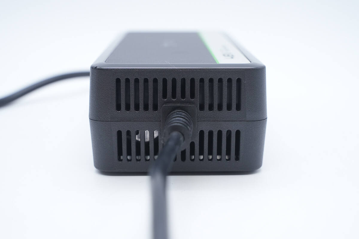
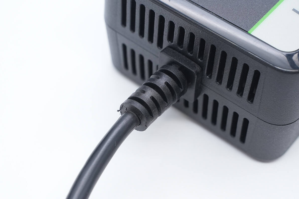
The DC output side also features a cooling grille with a cooling fan inside.
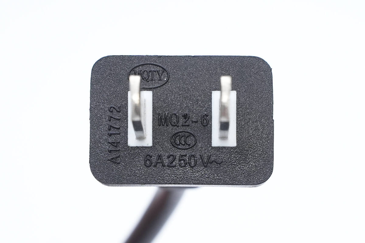
The input cable uses a two-pin plug rated at 6A 250V~, and it has passed CCC certification.
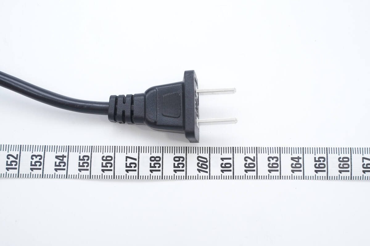
The length of the input cable is about 161 cm (63.39 inches).
The input cable features an anti-bending design.
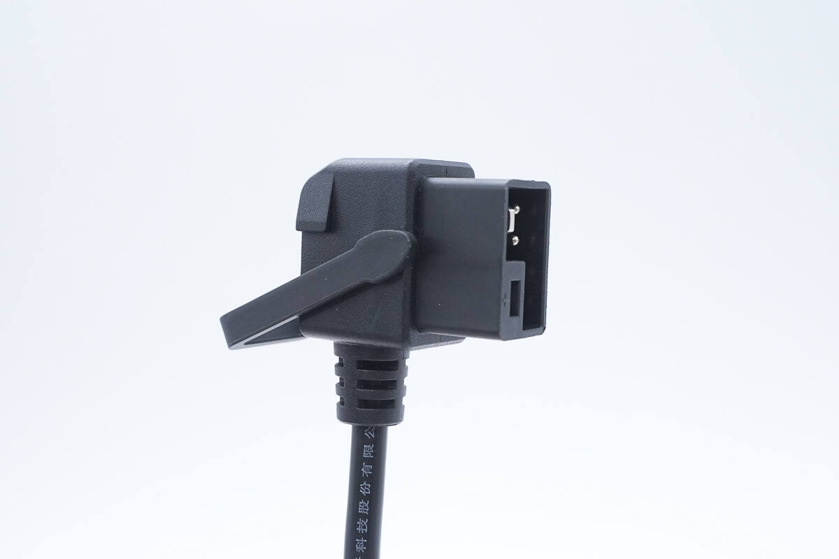
The output plug uses a new terminal design and is equipped with a handle.
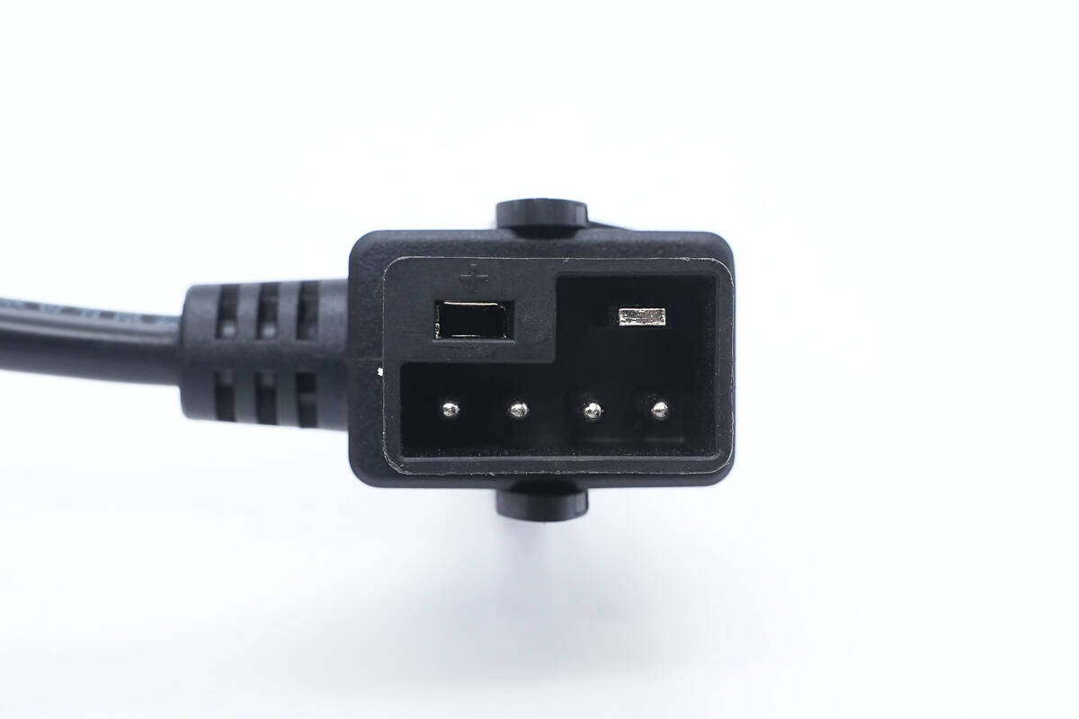
Close-up of the terminal: the positive pole has an independent chamber, preventing mismatches and significantly enhancing charging safety.
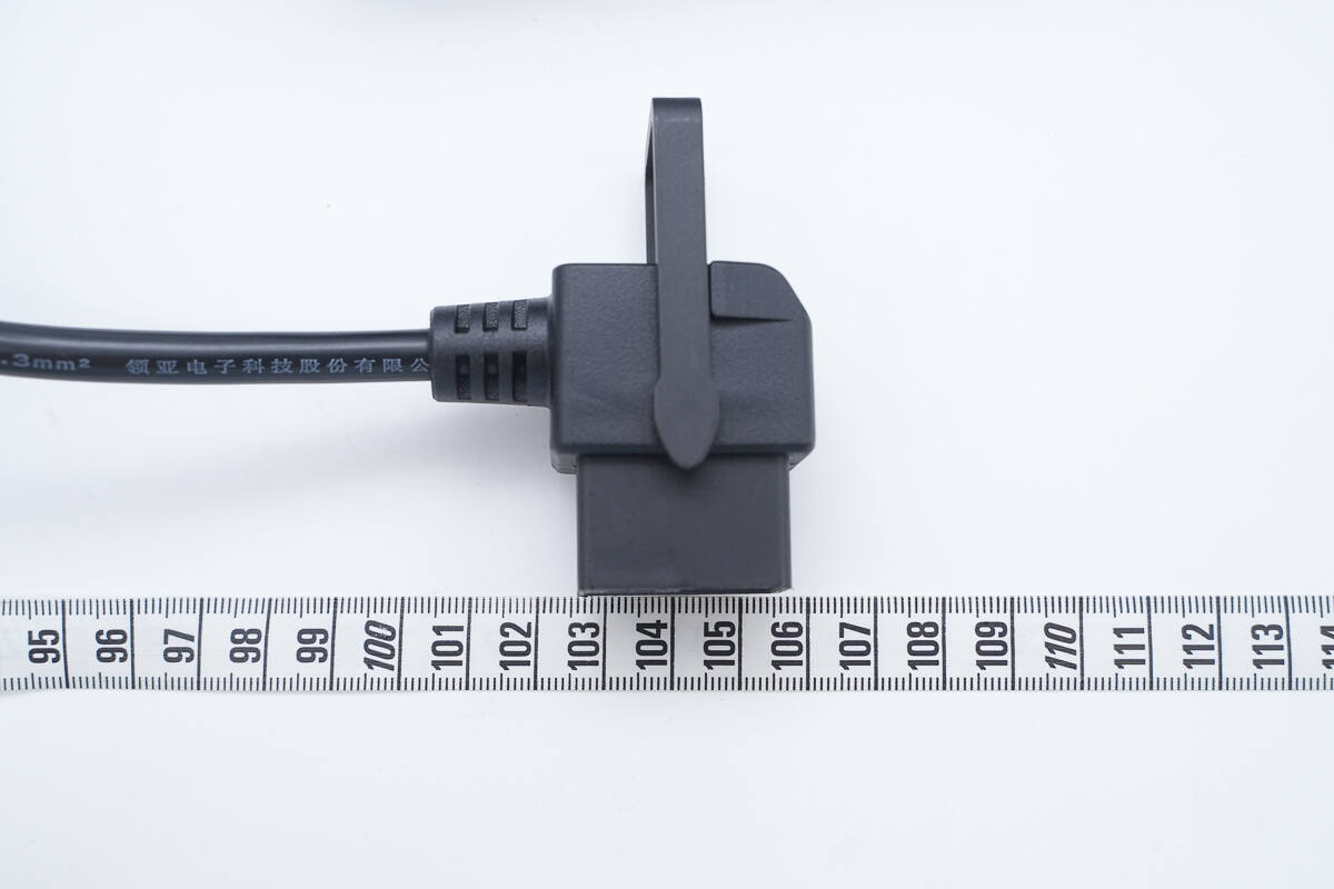
The length of the output cable is about 106 cm (41.73 inches).

The output cable has a four-core structure, with two cores of 1 mm² and two cores of 0.3 mm² cross-sectional area, used for charging and data communication.
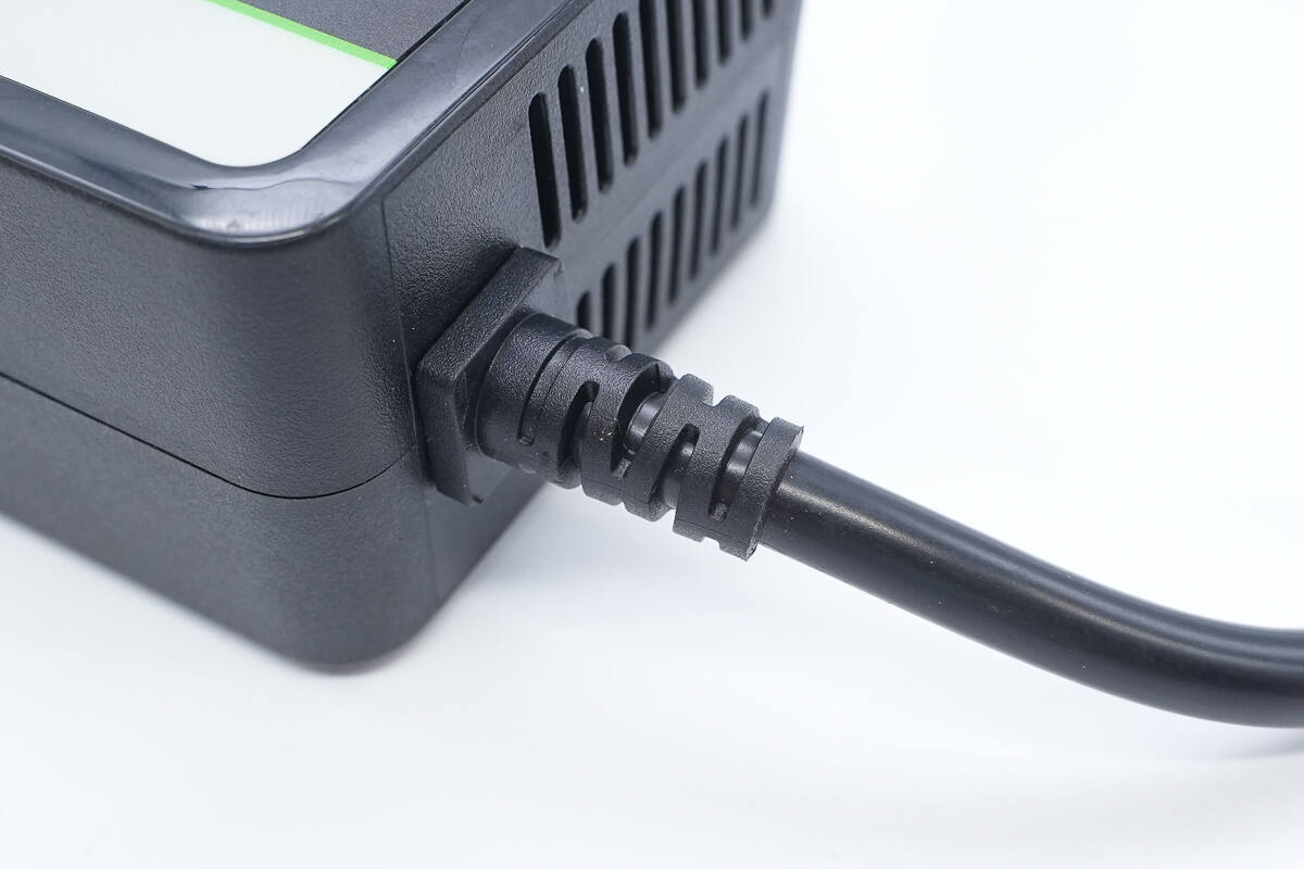
The output cable also features an anti-bending design.

The length of the charger is about 170.1 mm (6.7 inches).
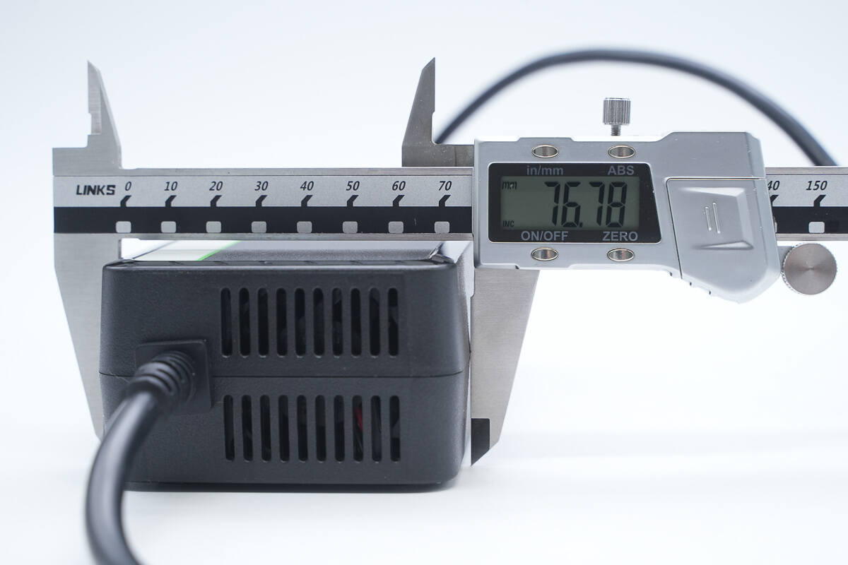
The width is about 76.8 mm (3.024 inches).
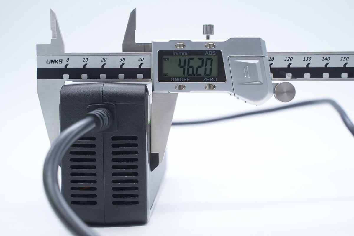
The thickness is about 46.2 mm (1.82 inches).
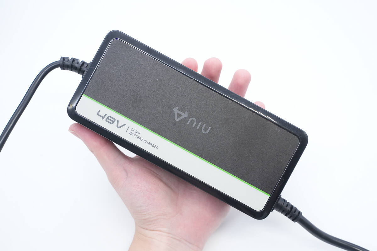
That's how big it is on the hand.
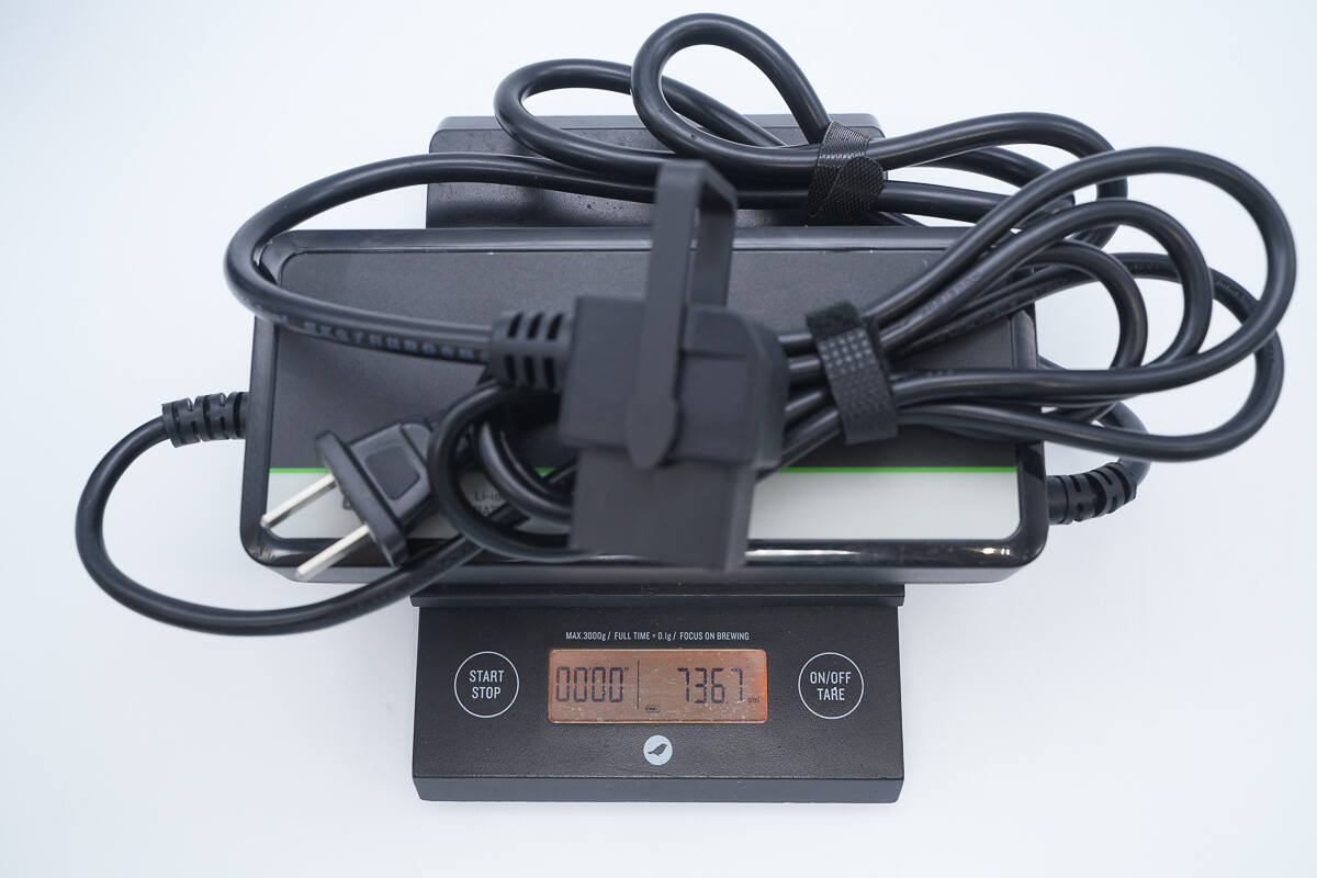
The weight is about 736 g (25.96 oz).
Teardown
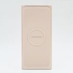
Next, let's take it apart to see its internal components and structure.
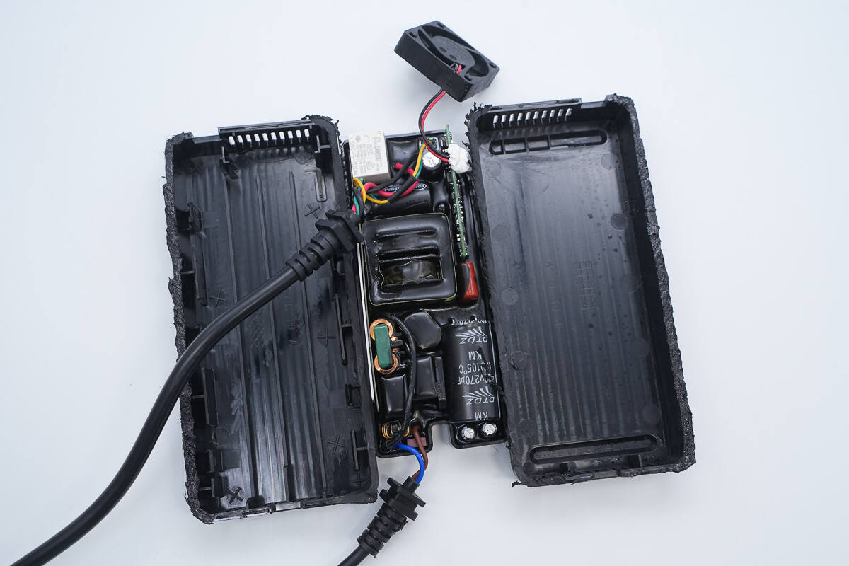
Cut along the seam to open the housing and remove the PCBA module.
Close-up of the LED indicator light guide strip.
The PCBA module has a plastic casing and is partially encapsulated.
The input cable is connected via soldering.
The output wire is also connected by welding, and the communication wire uses a crimped terminal with soldering.
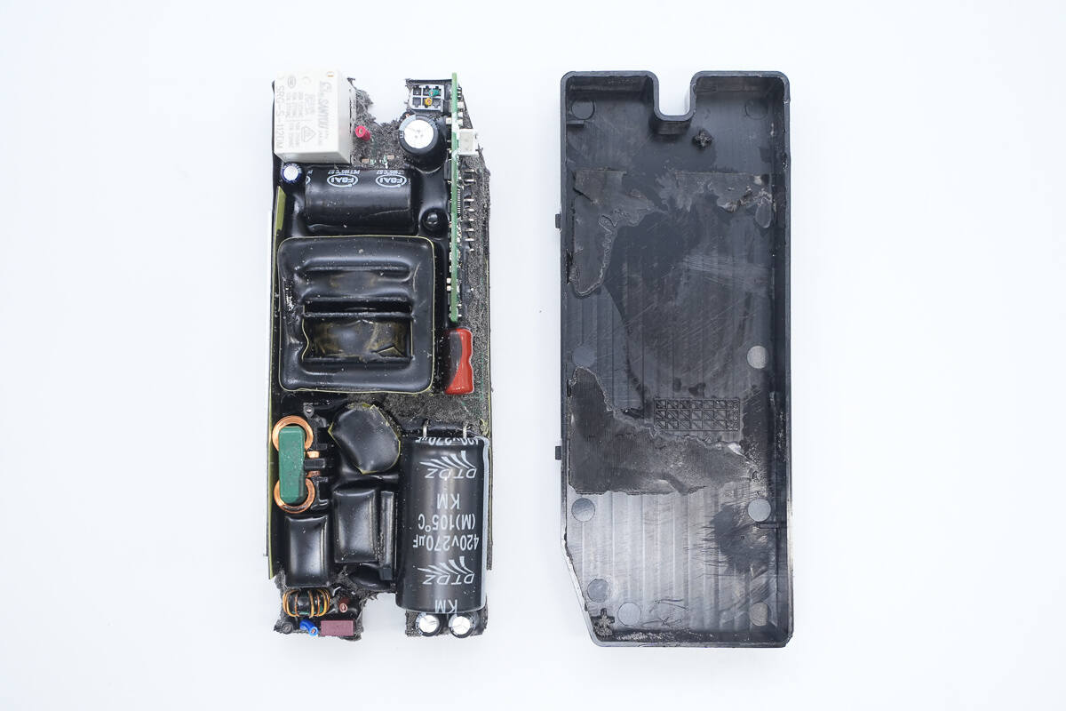
Remove the PCBA module from inside the casing.
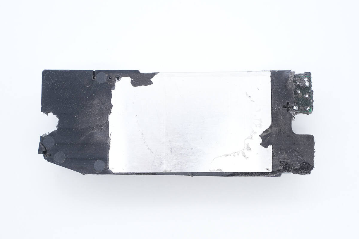
An aluminum heat sink is installed on the bottom of the PCBA module.
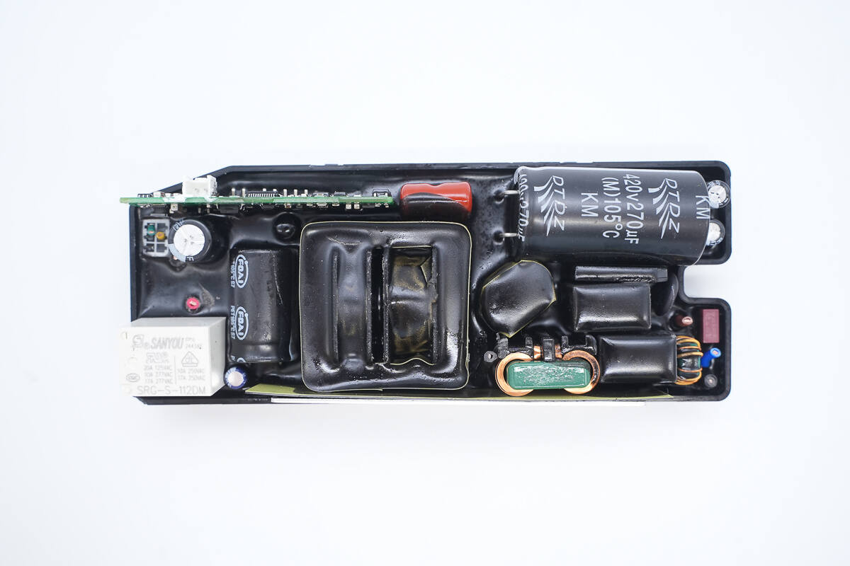
The components on the front side of the PCBA module are covered with potting compound.
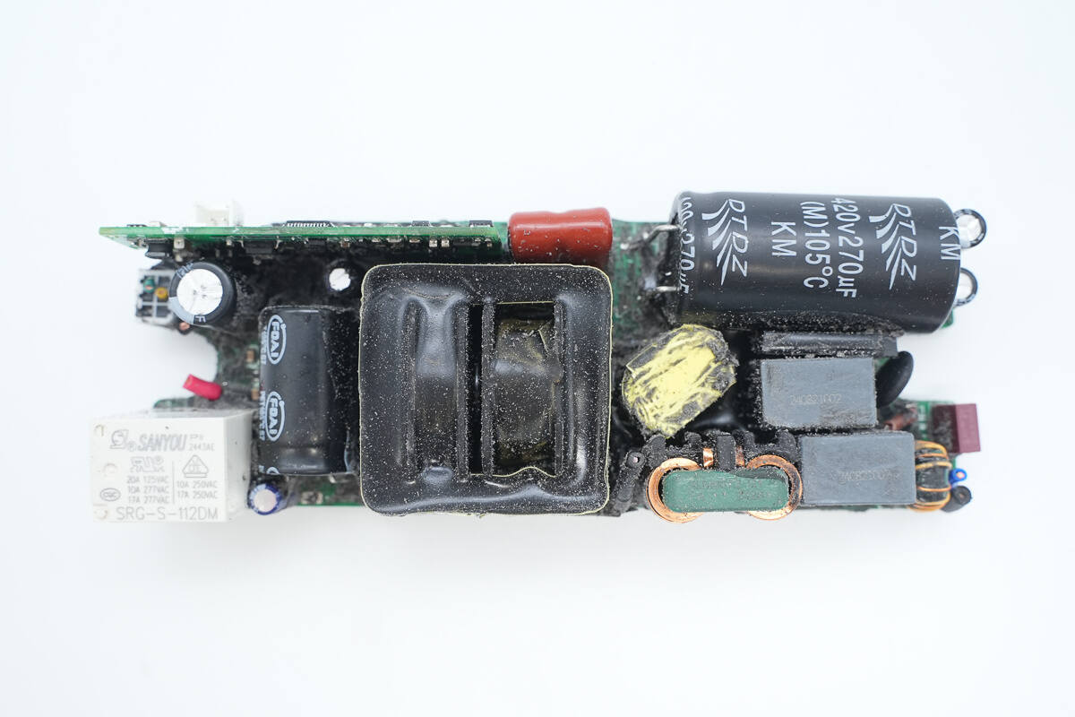
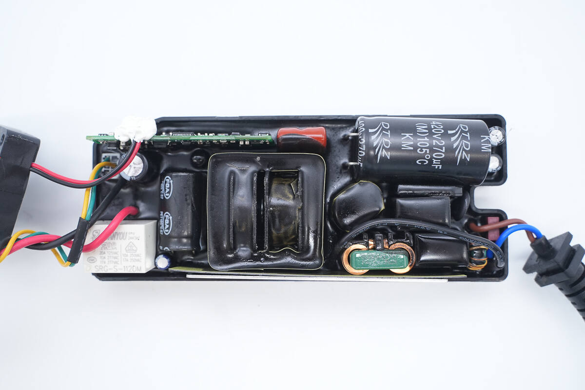
Remove the potting compound. The front side of the PCBA module contains components such as a fuse, common mode chokes, safety X2 capacitors, an NTC thermistor, a bridge rectifier, a high-voltage filter capacitor, a transformer, a resonant capacitor, a resonant inductor, and a relay.
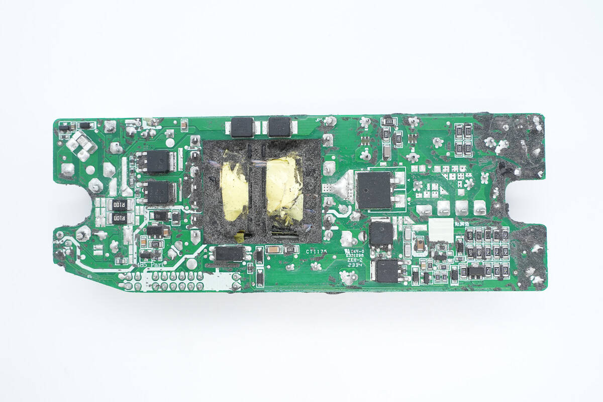
The transformer on the back side is the one on the front, and the PCB is cut out to reduce thickness. Other components include LLC MOSFETs, ultra-fast recovery diodes, synchronous rectifiers, and current-sensing resistors.
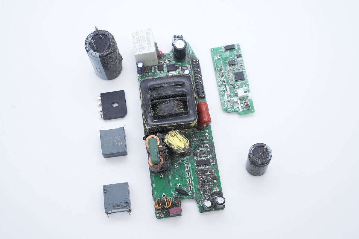
Remove the control PCB, filter capacitors, bridge rectifier, and safety X2 capacitors.
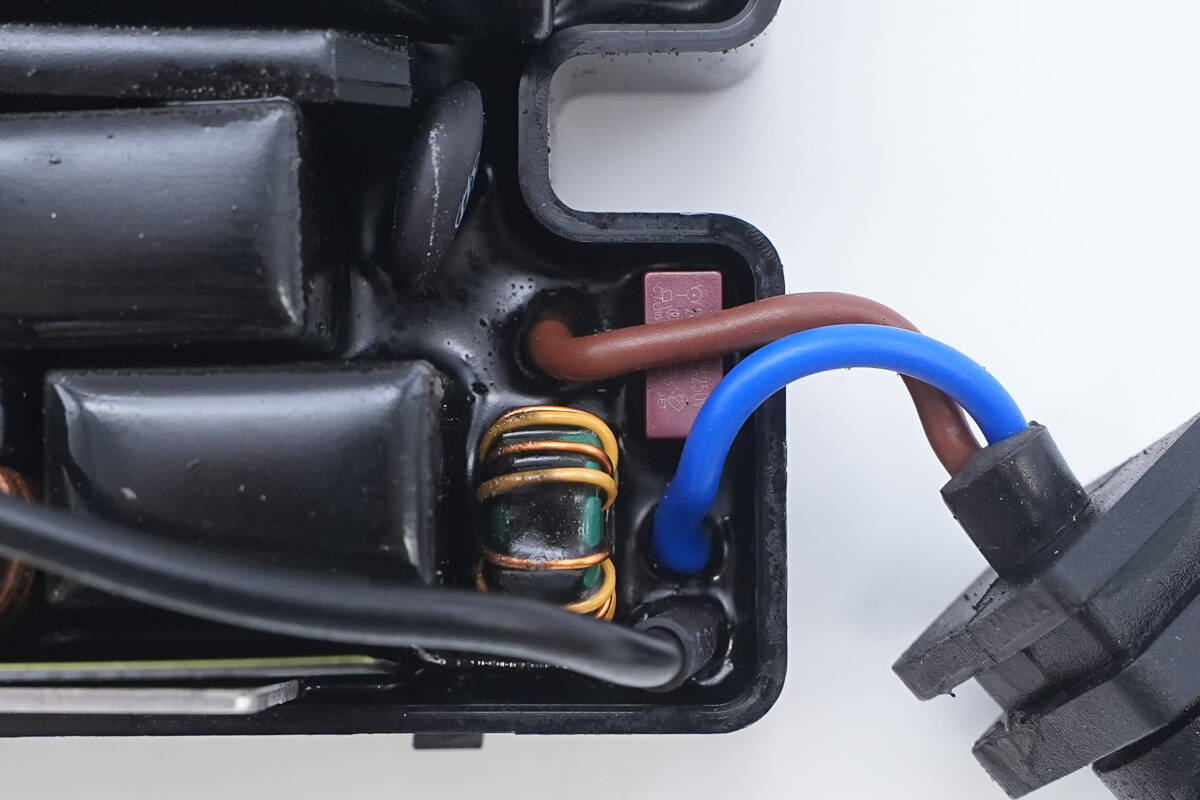
The input end is equipped with a fuse, a common mode choke, safety X2 capacitors, an NTC thermistor, and a high-voltage filter capacitor.
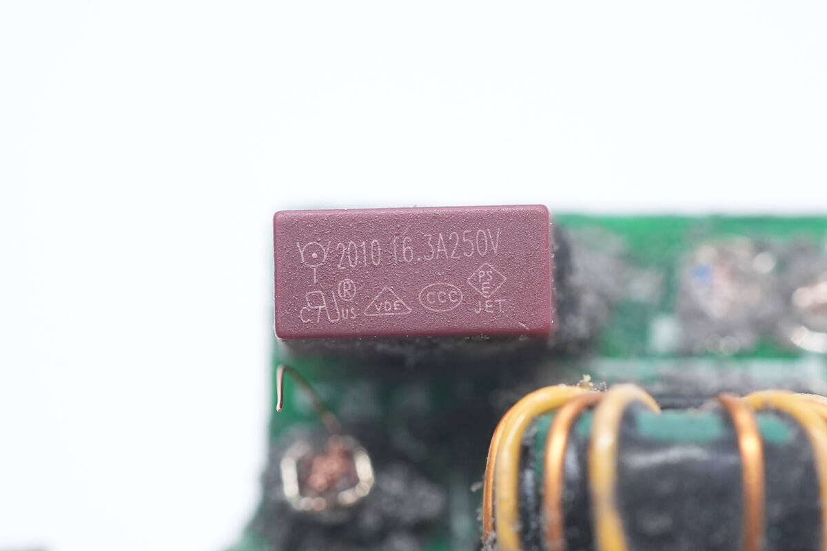
The fuse is from WalterFuse and is rated at 6.3A 250V.
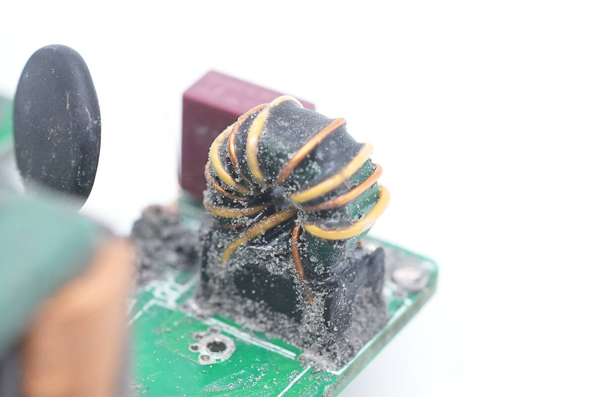
The common mode choke is made of enameled and insulated wire and has an insulated support at the bottom.
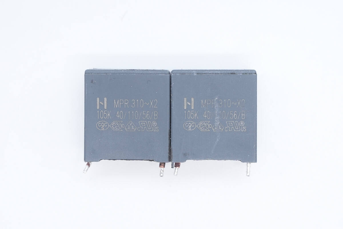
The safety X2 capacitors are rated at 1μF.
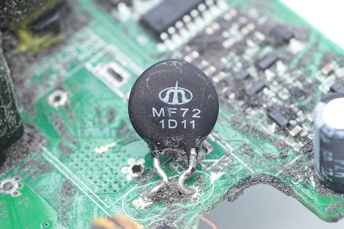
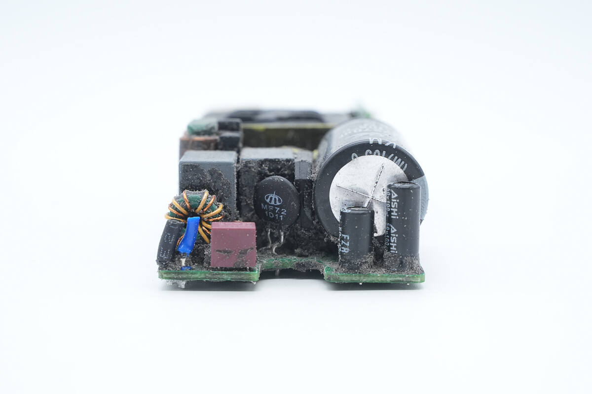
The NTC thermistor is from Shiheng, part of the MF72 series, marked with D11, and is used to suppress surge current upon power-up.
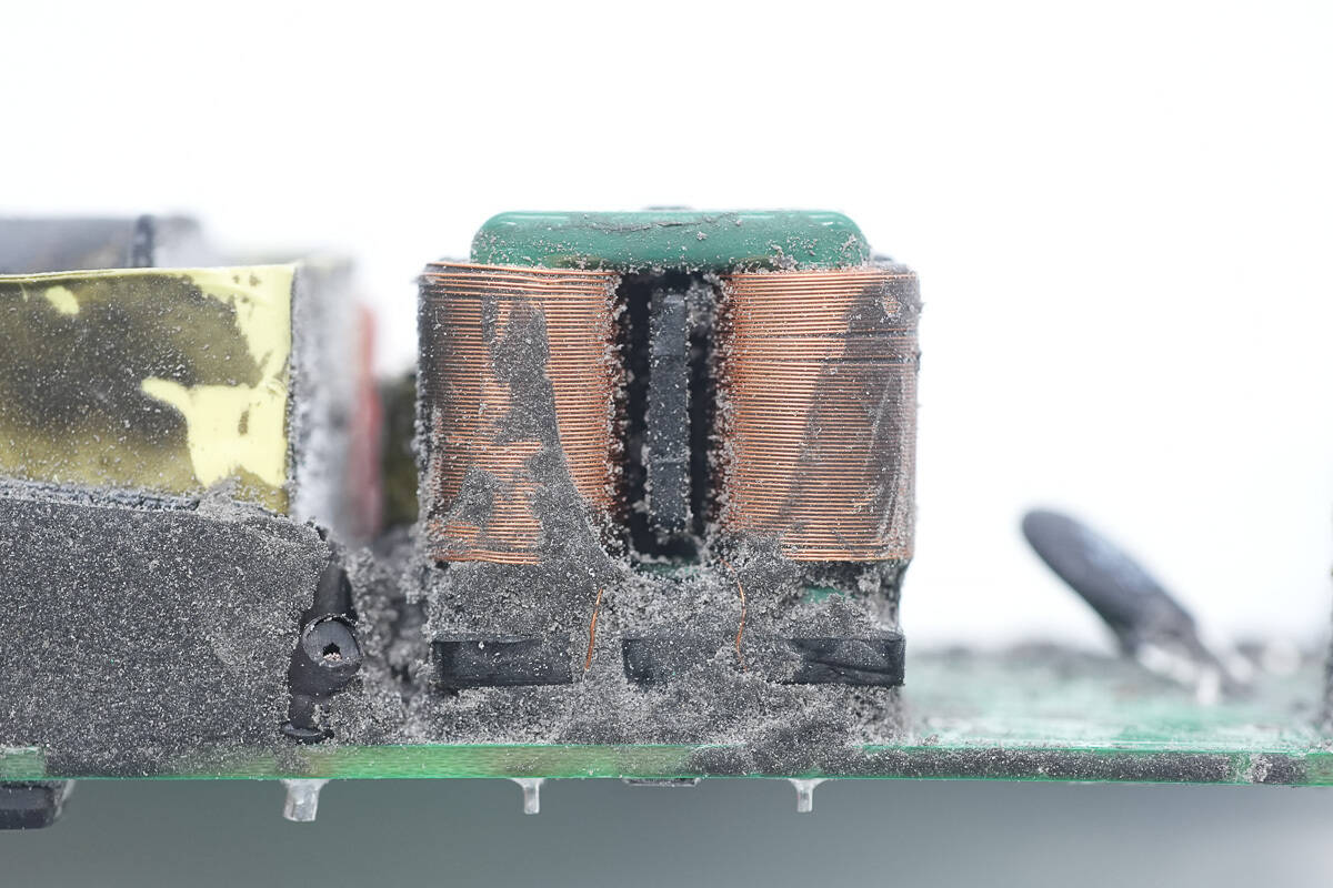
The common mode choke is made by winding flat copper wire.
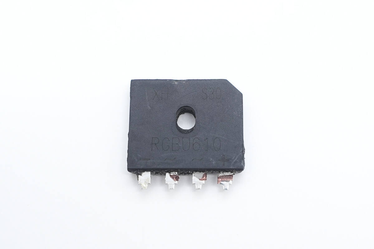
The bridge rectifier, model RGBU610, is rated for 1000V6A and is packaged in a GBU package.
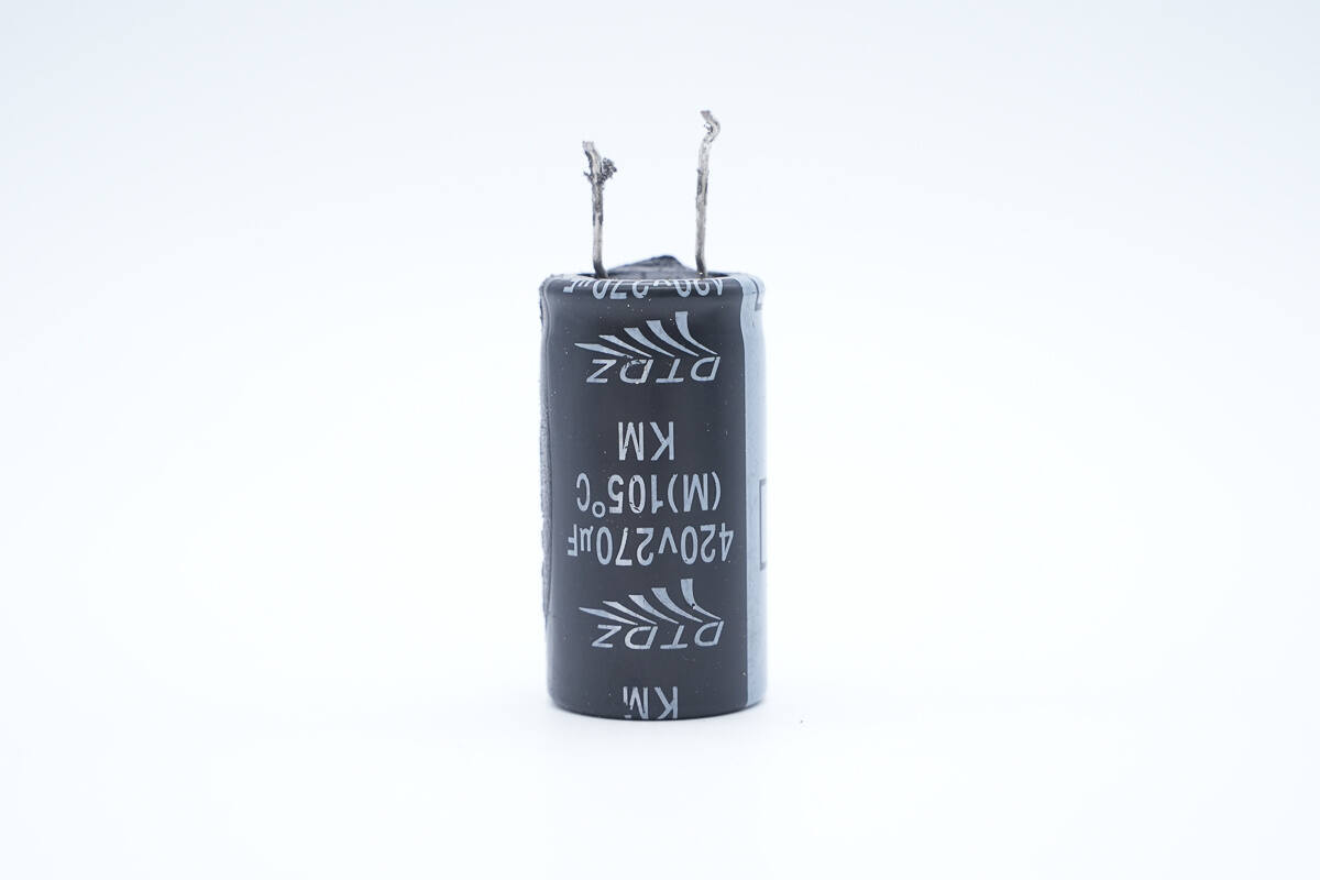
The high-voltage filter capacitor is from DTDZ and is rated at 420V 270μF.
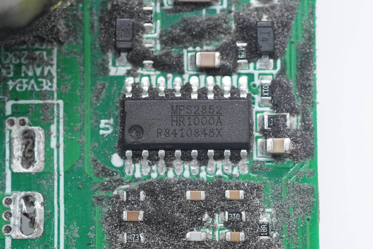
The LLC controller, model HR1000A, is from MPS. It is specifically designed for resonant half-bridge topologies, providing two drive signal channels and outputting complementary signals with a 50% duty cycle. An internally fixed 350ns dead time ensures zero-voltage switching of the two complementary gate signals during transients, supporting high-frequency operation. The chip integrates a bootstrap diode and multiple protection functions, and is packaged in an SO-16 package.
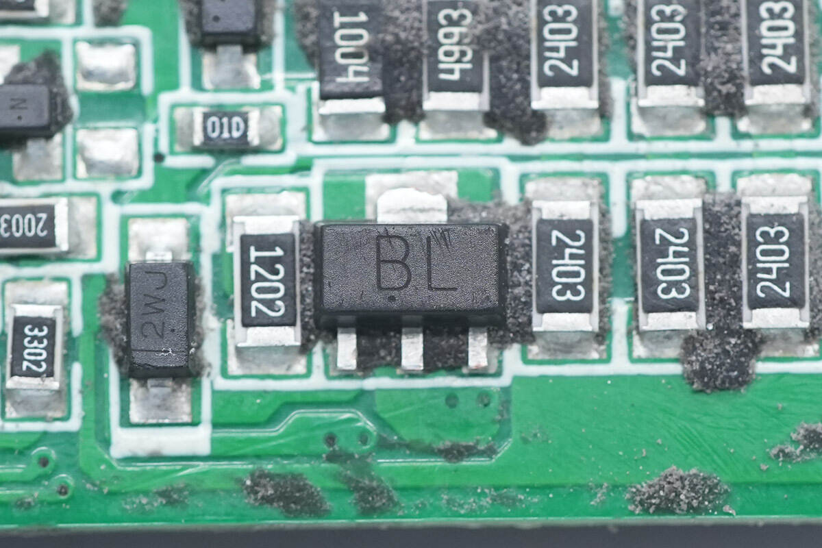
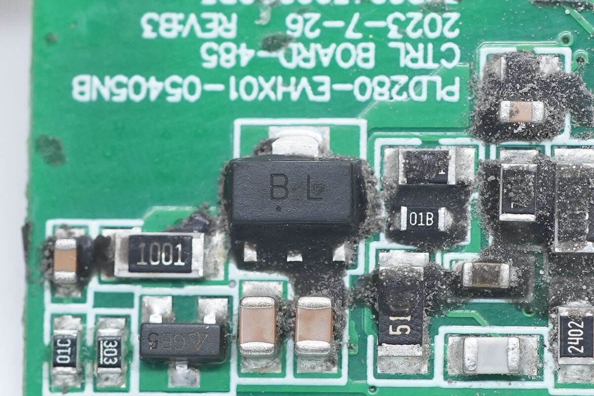
The transistor used for power supply regulation is from JSCJ, marked with BL, model BCX56-16, is an NPN transistor, rated at 100V 1A, and uses an SOT-89-3L package.
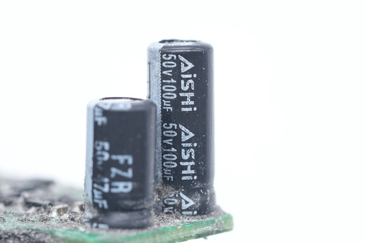
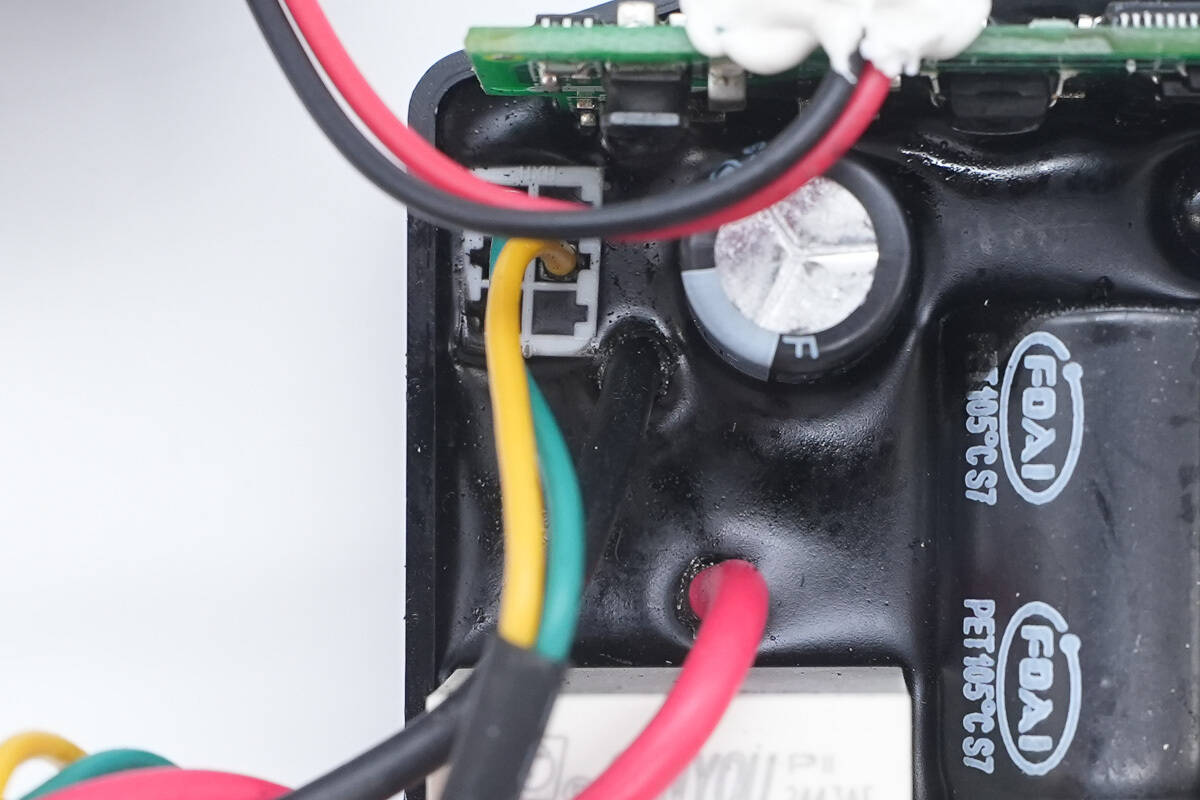
The filter capacitor supplying power to the master control chip is from AiSHi, with a specification of 50V 100μF.
The other capacitor is from Faratronic.
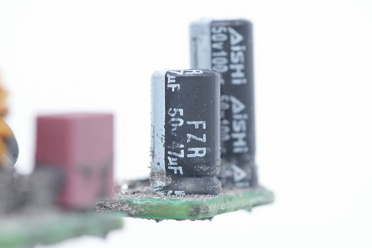
The capacitor is an FZR series low-impedance, long-life type, with a specification of 50V 47μF.

The LLC MOSFETs are from WAYON, model WMO26N65F2, NMOS, with a voltage rating of 650V, an on-resistance of 170mΩ, and a TO-252 package.
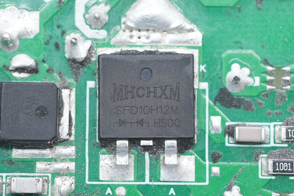
The ultra-fast recovery diode is from MHCHXM, model SFD10H12M, rated at 1200V 10A, and packaged in TO-263M-2L.
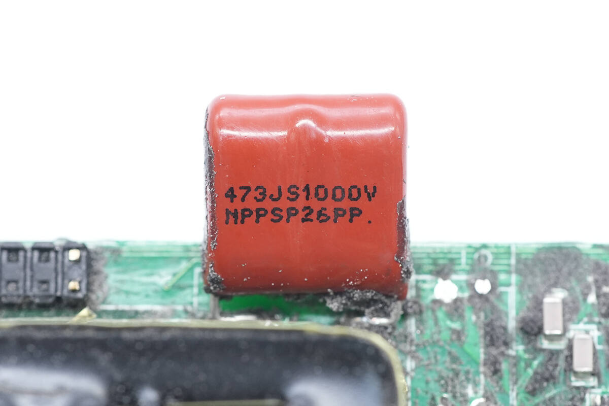
The resonant capacitor is rated at 0.047μF 1000V.
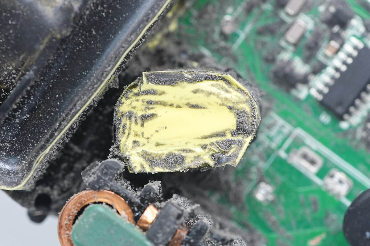
The resonant inductor is tightly insulated with tape.
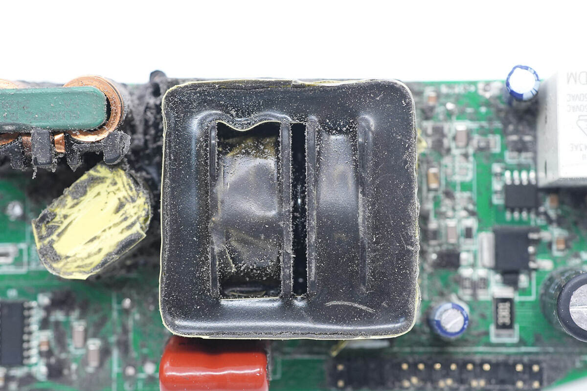
The magnetic core of the transformer is insulated with tape.
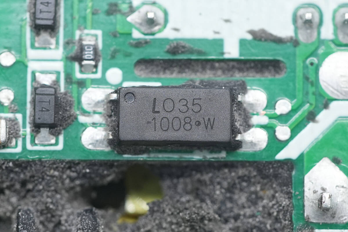
The LITEON LTV-1008 optocoupler is used for output voltage feedback.
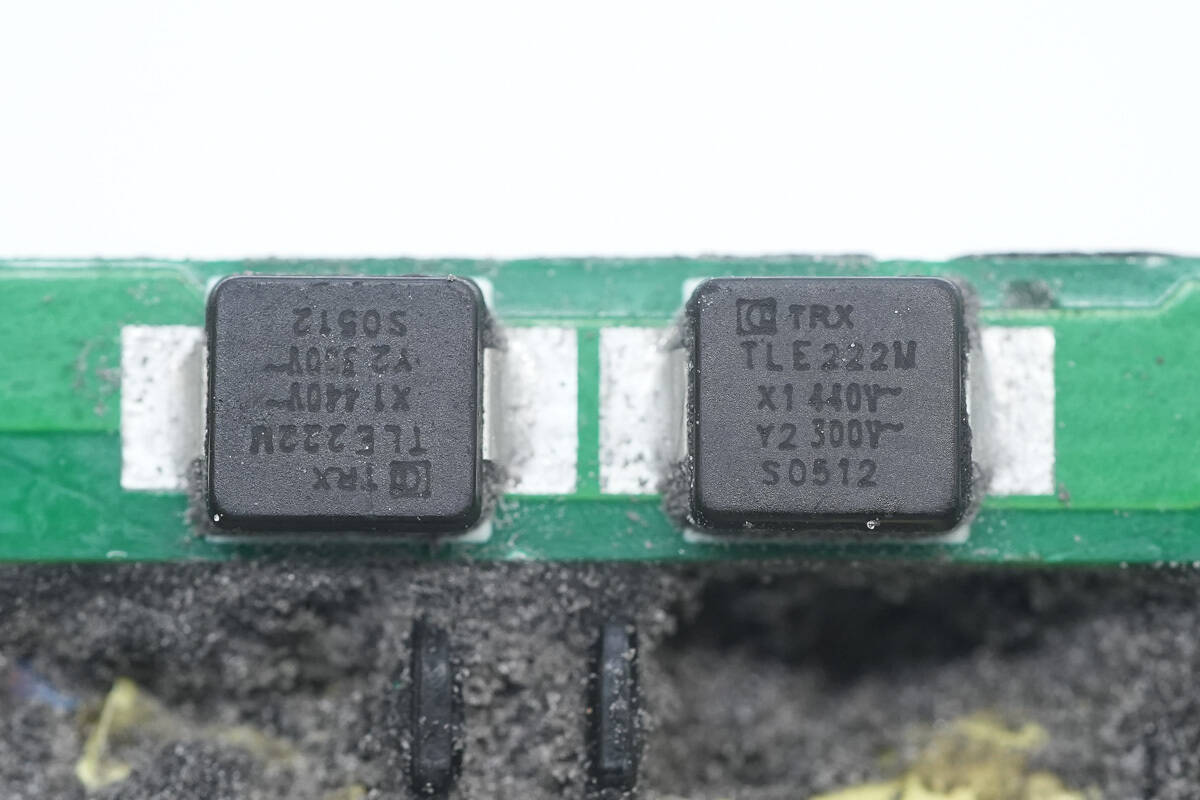
The SMD Y capacitors are from TRX. Its compact size and light weight make it well-suited for high-density power products such as GaN fast chargers. The part number is TAY2222ME.
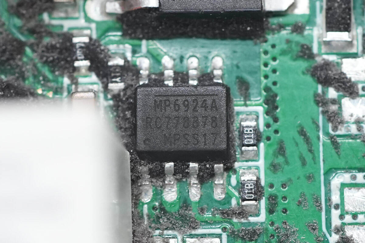
The synchronous rectifier controller, model MP6924A, is from MPS. It is an LLC synchronous rectifier controller with enhanced anti-interference capabilities and a fast shutdown function, compatible with CCM/DCM modes. The MP6924A integrates two synchronous rectifier controllers, one for each of the two secondary coil outputs of the LLC converter, suitable for synchronous rectification applications in LLC converters. It is packaged in an SOIC-8 package.
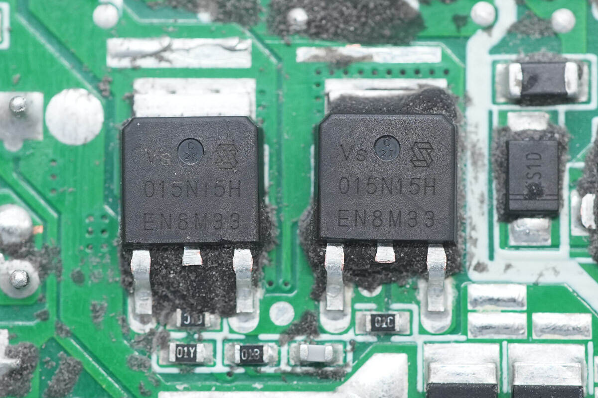
The synchronous rectifiers are from Vergiga, model VSD015N15HS-G, NMOS, with a withstand voltage of 150V, an on-resistance of 14.5mΩ, and a TO-252 package.
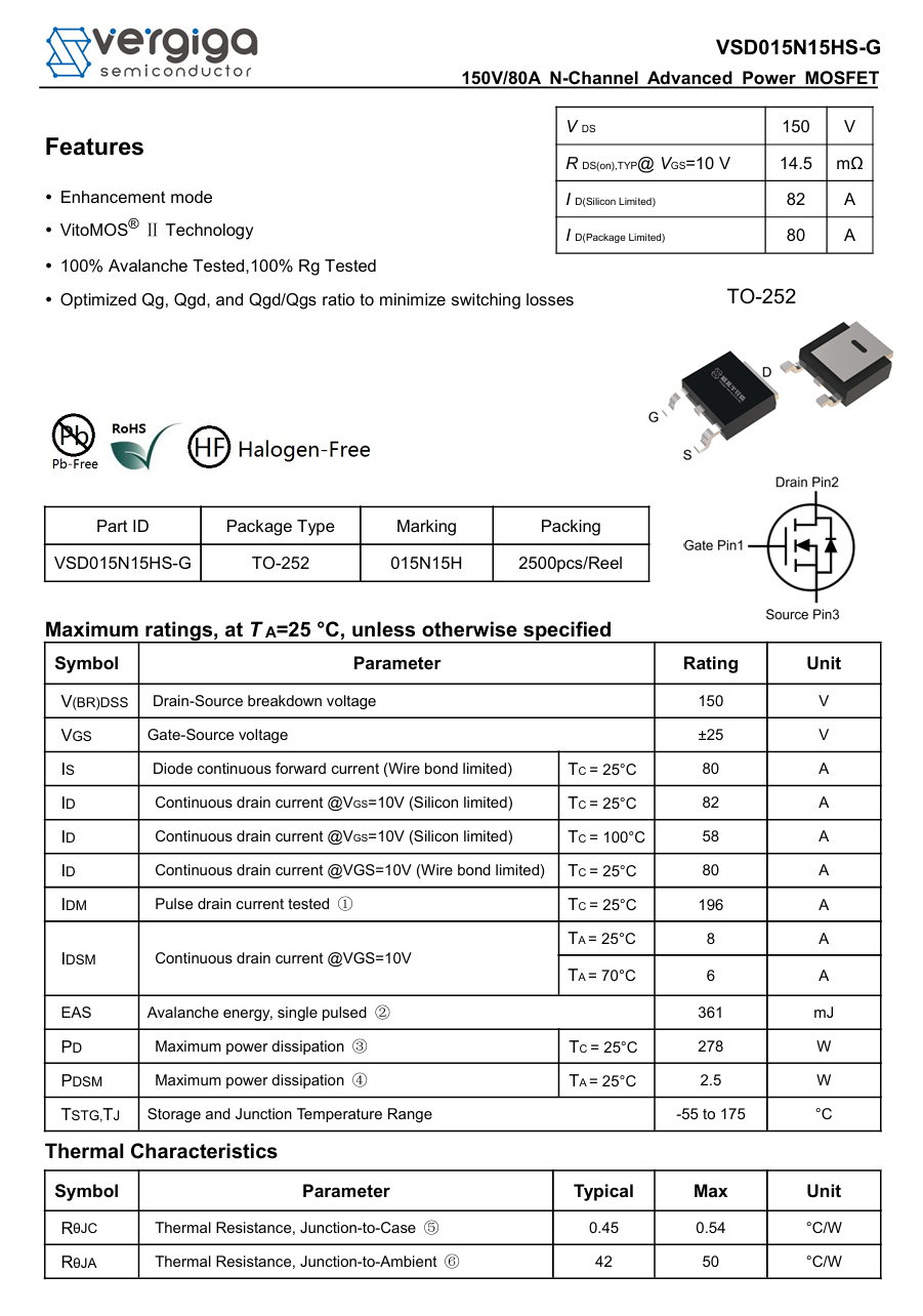
Here is the information about Vergiga VSD015N15HS-G.
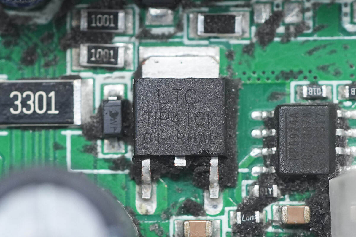
The transistor powering the synchronous rectifier controller is from Unisonic, model TIP41C, an NPN transistor with a specification of 100V 6A, and a TO-252 package.
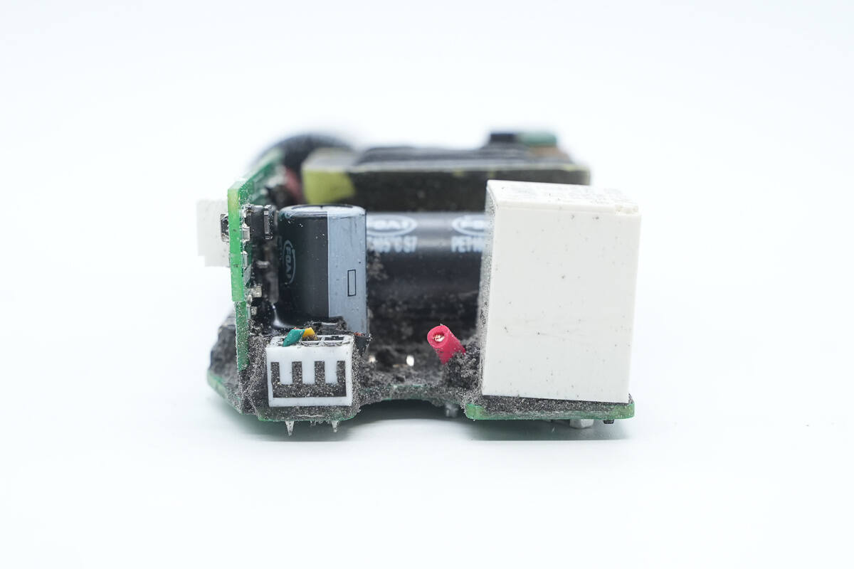
The output end is equipped with a control PCB, filter capacitors, and a relay.
The output filter capacitor is from Faratronic.
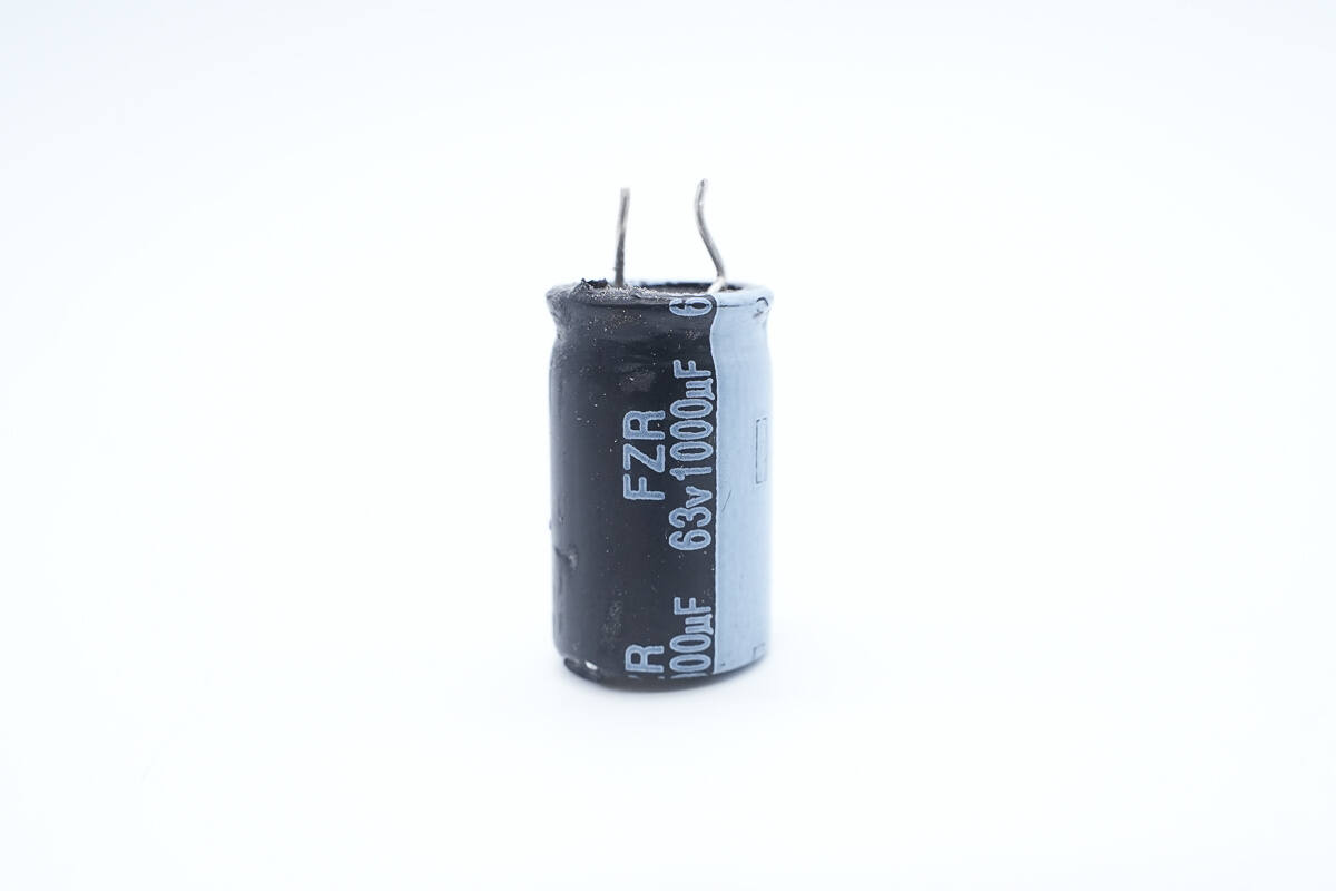
The capacitor is from the FZR series, with a specification of 63V 1000μF.
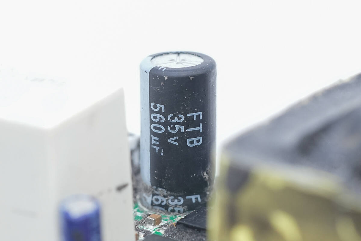
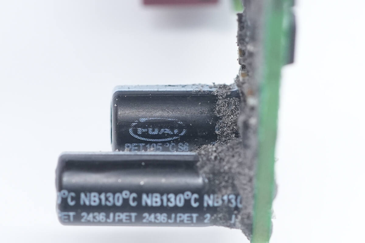
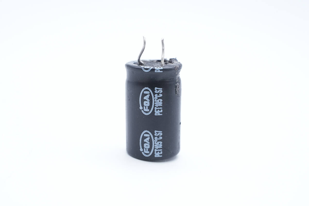
The other filter capacitor is an FTB series ultra-high temperature resistant capacitor, with a temperature resistance of 130℃ and a specification of 35V 560μF.
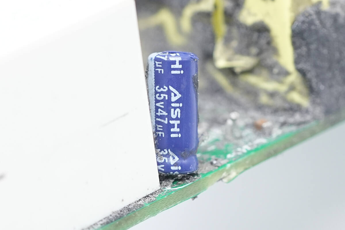
This filter capacitor is from AiSHi and is rated at 35V 47μF.
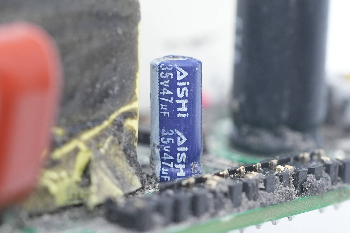
The other filter capacitor has the same specifications.
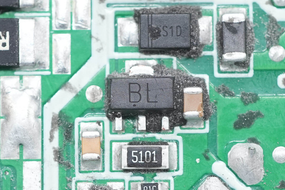
The transistor used for power supply regulation is from JSCJ, model BCX56-16.

Two 100mΩ resistors are connected in parallel to detect the output current.
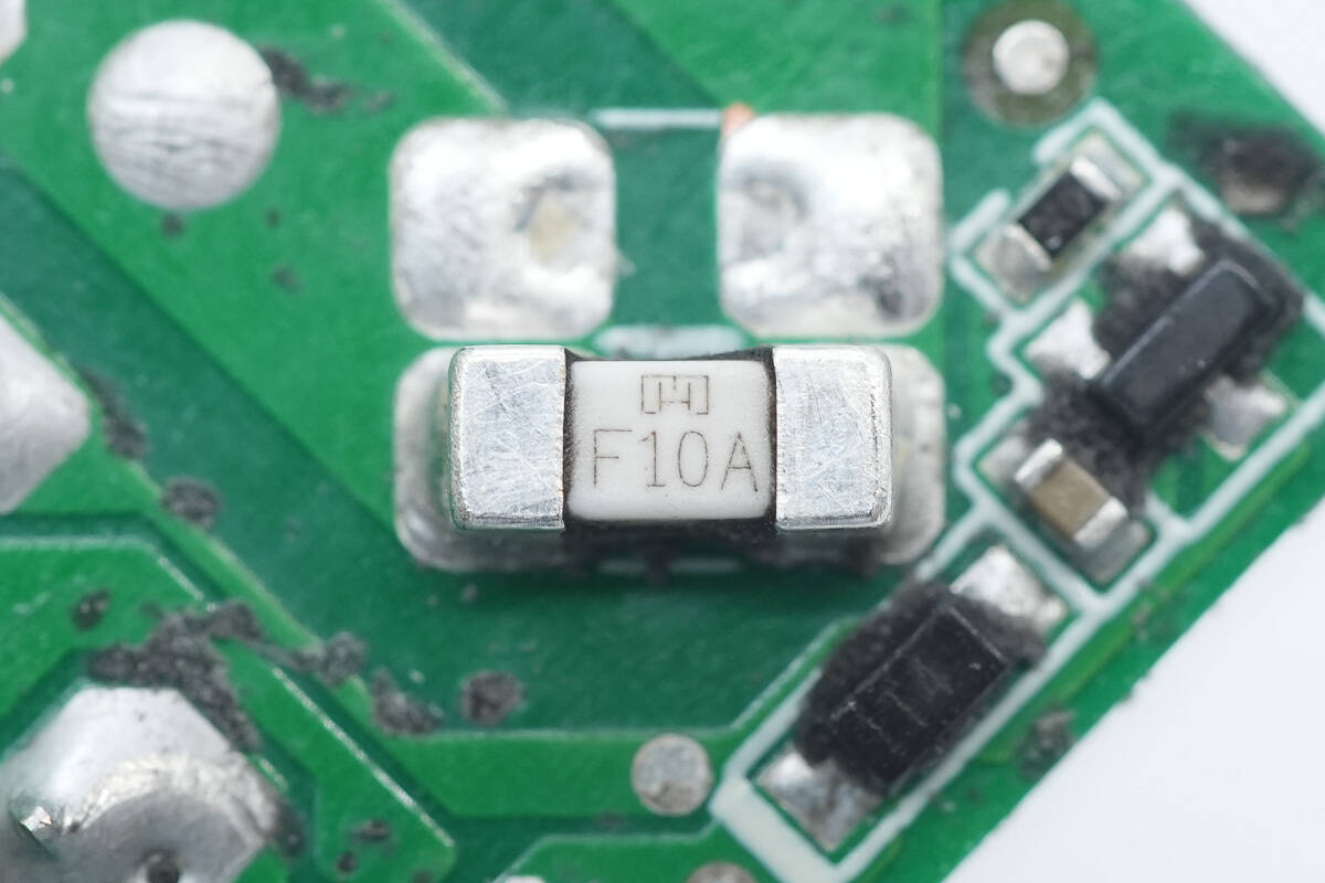
The SMD fuse is rated for 10A.
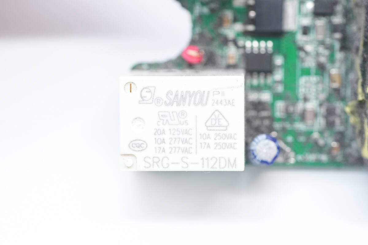
The output control relay, model SRG-S-112DM, has a built-in set of normally open contacts with a contact capacity of 17A250VAC and a coil voltage of 12V.
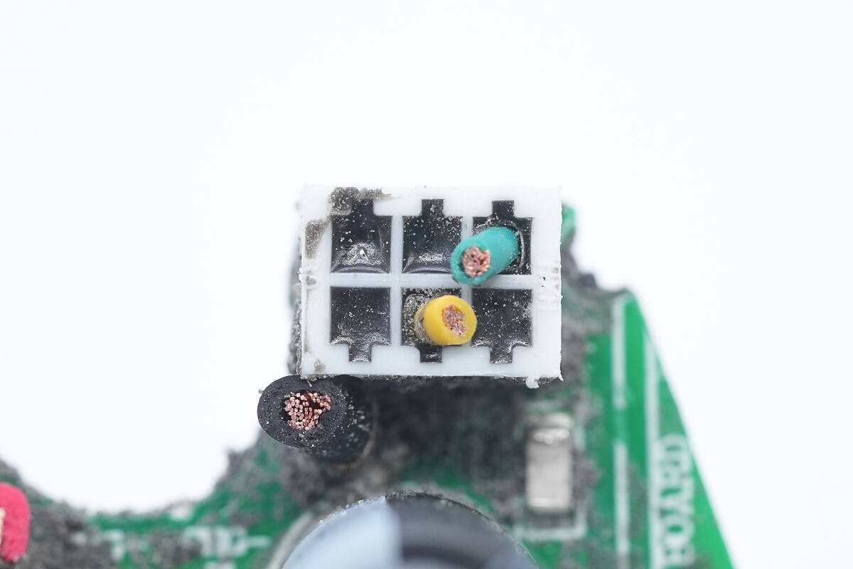
Close-up of the output wire connection terminal.
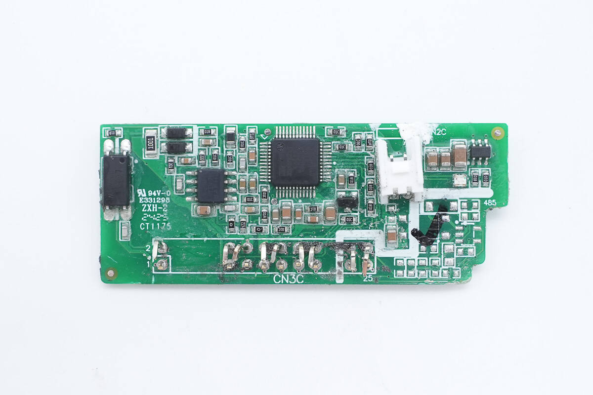
The control PCB has an MCU, operational amplifier, isolation optocoupler, indicator light, and synchronous buck chip on the outside.
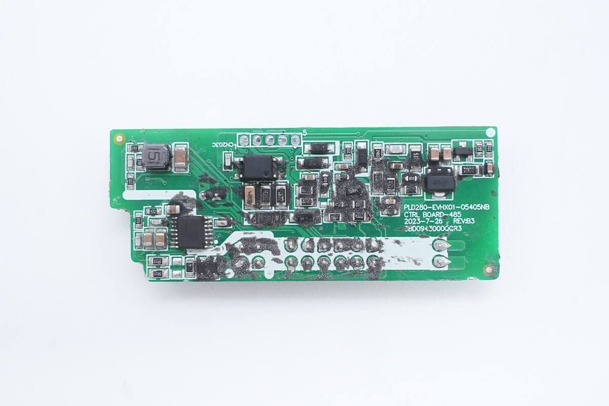
On the other side are a 485 communication chip, an isolation optocoupler, and a transistor.
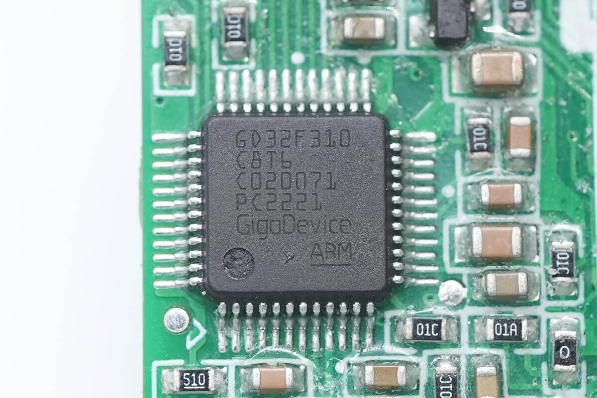
The MCU is from GigaDevice, model GD32F310C8T6, which integrates an Arm® Cortex®-M4 core, 64KB FLASH, and 8KBSRAM. It achieves excellent cost performance in terms of enhanced processing power, reduced power consumption, and peripheral configuration, and is packaged in LQFP48.
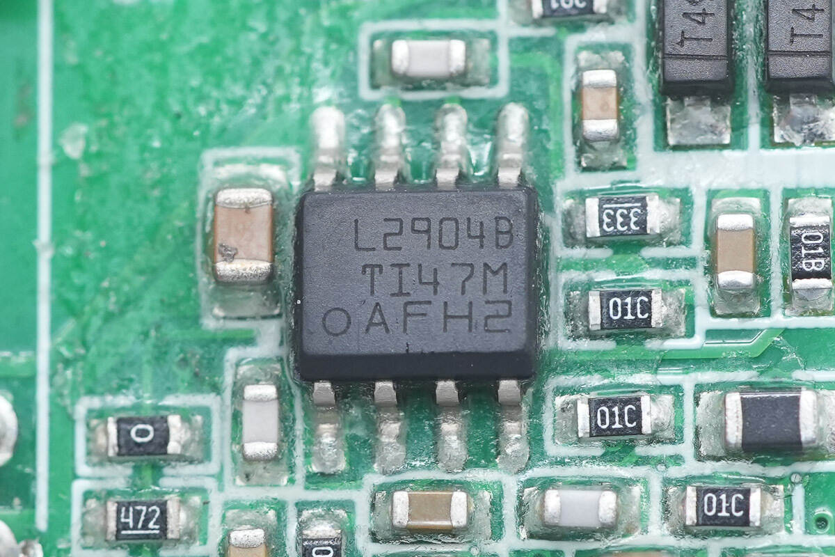
The operational amplifier is from Texas Instruments, model LM2904B, which is an industry-standard dual operational amplifier that supports a 36V operating voltage and an operating temperature of -40~125℃, and is packaged in SOIC8.
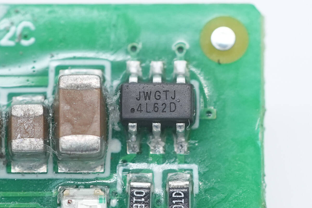
The synchronous buck chip, model JW5126, is from JOULWATT and is marked with JWGT. It is a synchronous buck converter with an input voltage of 4.5-65V. The chip integrates MOSFETs, has an output current of 200mA, extremely high light-load efficiency, adjustable peak current limit, output short-circuit and over-temperature protection, and is packaged in an SOT23-6 package.

Close-up of a 150μH buck inductor.
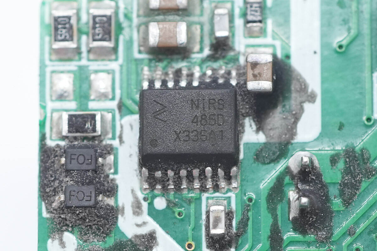
The 485 communication chip is from NOVOSENSE, model NiRS485, supports 3000Vrms insulation voltage, and is suitable for BMS, isolating 485 communication, smart meters, and safety protection detection, and is packaged in SSOP16.
A close-up of the JSCJ BCX56-16 transistor.
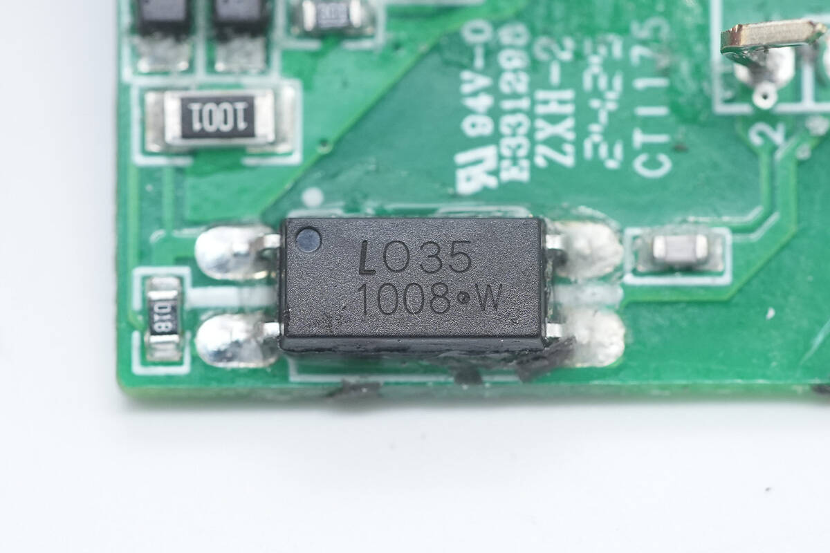
A close-up of the LITEON LTV1008 isolation optocoupler.
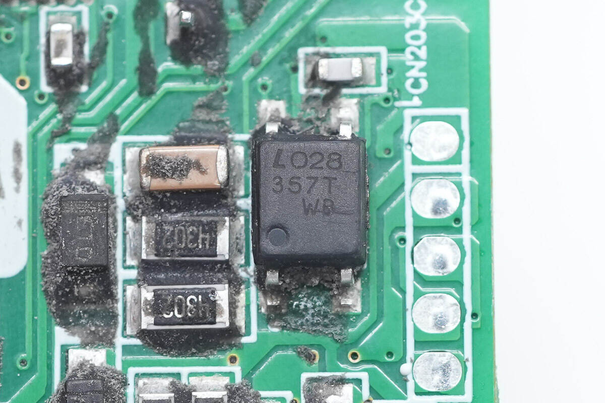
Close-up of LITEON LTV357 isolation optocoupler.
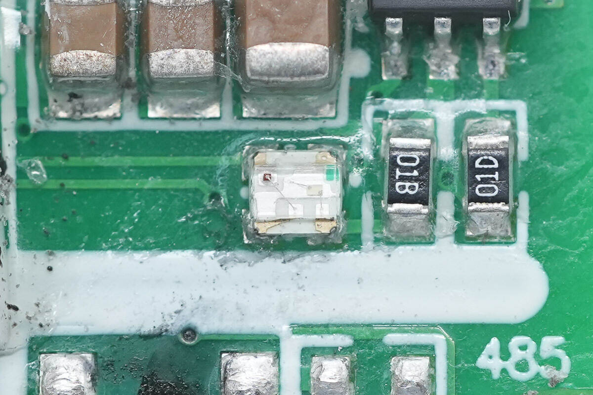
Close-up of the LED indicator light.
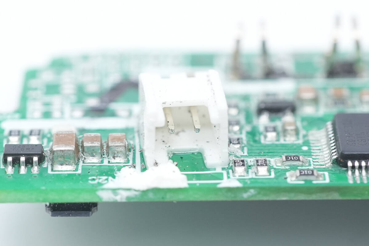
Close-up of the socket for the cooling fan.
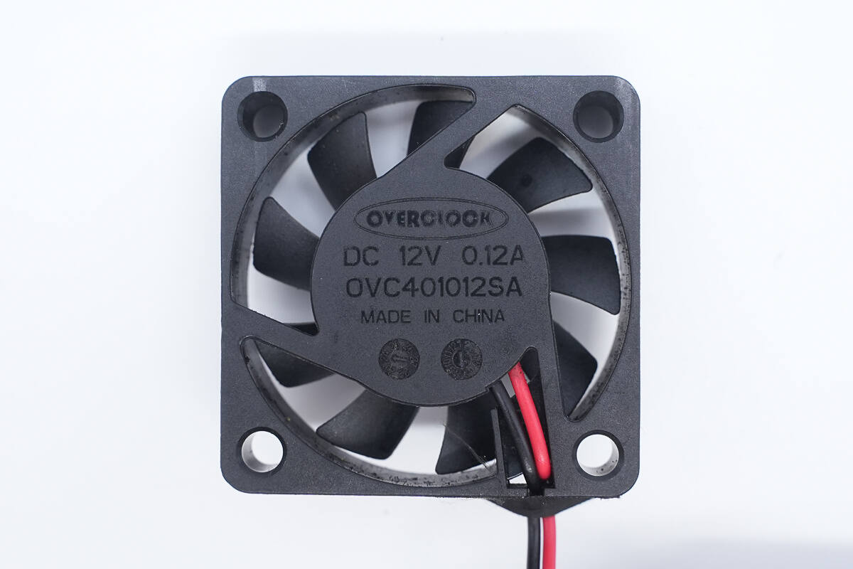
The cooling fan is from OVERCLOCK, model OVC401012SA, with a specification of 12V 0.12A.
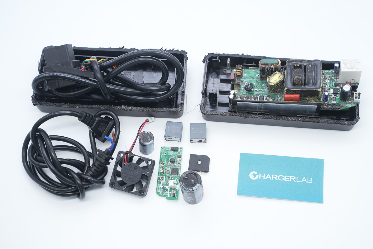
Well, those are all components of the NIU 280W E-bike Charger.
Summary of ChargerLAB
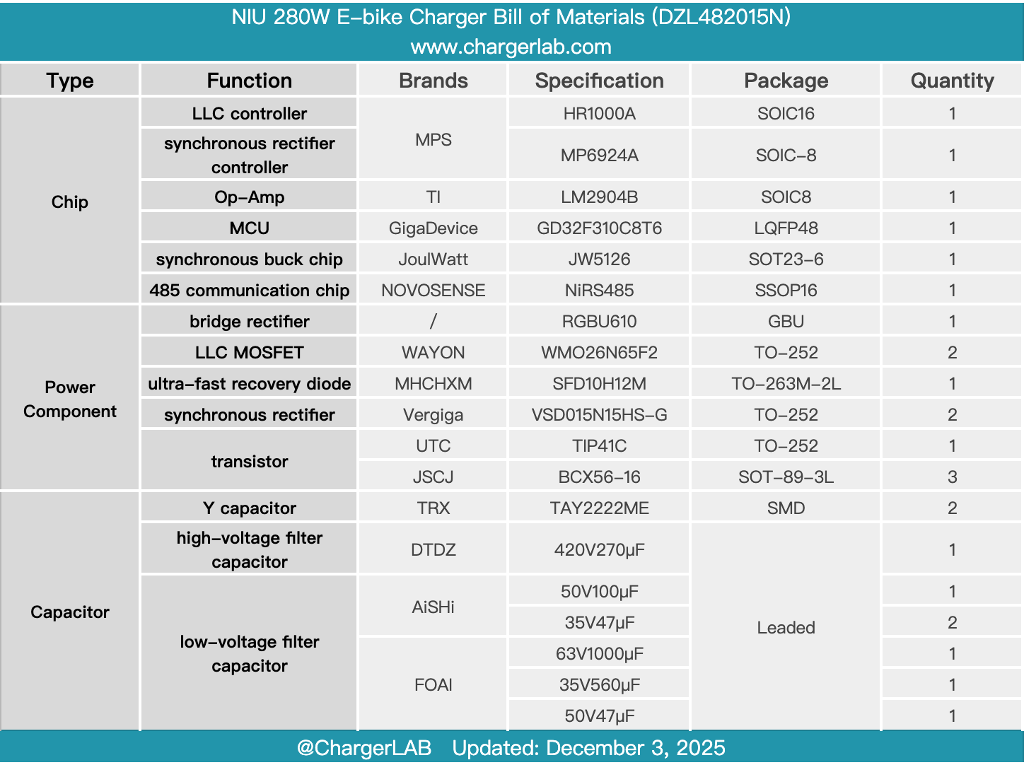
Here is the component list of the NIU 280W E-bike Charger for your convenience.
It features 280W charging power, a maximum output current of 5.2A, and a maximum output voltage of 54.6V. It comes with input and output cables. The plastic casing houses a cooling fan and includes a charging indicator light for easy monitoring of the charging status.
After taking it apart, we found that it uses a potting process and has an aluminum alloy heat sink. It uses an LLC+ synchronous rectification architecture and has a separate control PCB. The controllers are all from MPS, using an HR1000A LLC controller paired with an MP6924A synchronous rectifier controller.
The LLC MOSFETs are WAYON WMO26N65F2, the synchronous rectifiers are Vergiga VSD015N15HS-G, and the charging control is handled by a GigaDevice GD32F310C8T6 MCU. A NOVOSENSE NiRS485 communication chip is included for communication with the battery pack, and a JOULWATT JW5126 is used for high-voltage step-down to power the MCU. A relay is provided at the output for output control, and a fuse is used for overcurrent protection. The components and workmanship are robust and reliable.
Related Articles:
1. Teardown of GreatWall SPARK 850W GaN 80 PLUS Gold Fully Modular Power Supply (G-850)
2. Teardown of Xiaomi 67W GaN Charger (MDY-19-EA)
3. Teardown of Gospower 3000W Switching Power Supply (G1236-3000WNA)