Introduction
Newsmy has launched a multifunctional portable power station, the P72, designed for outdoor scenarios such as camping, cycling, and fishing. It features both DC input and output ports, supporting solar charging. With a large 72,000mAh capacity, it offers excellent battery life.
The device also comes with two USB-A ports, two USB-C ports, an LED light, and a digital display. It supports up to 100W PD bi-directional fast charging. Users can monitor remaining battery life and charging status via the LED display. The P72 also supports emergency lighting and distress signaling, making it a versatile and practical outdoor companion. Next, let’s take it apart to see its internal components and structure.
Product Appearance
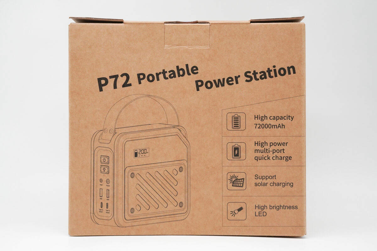
The front of the packaging box features the product name, an outline image of the device, and four selling points.
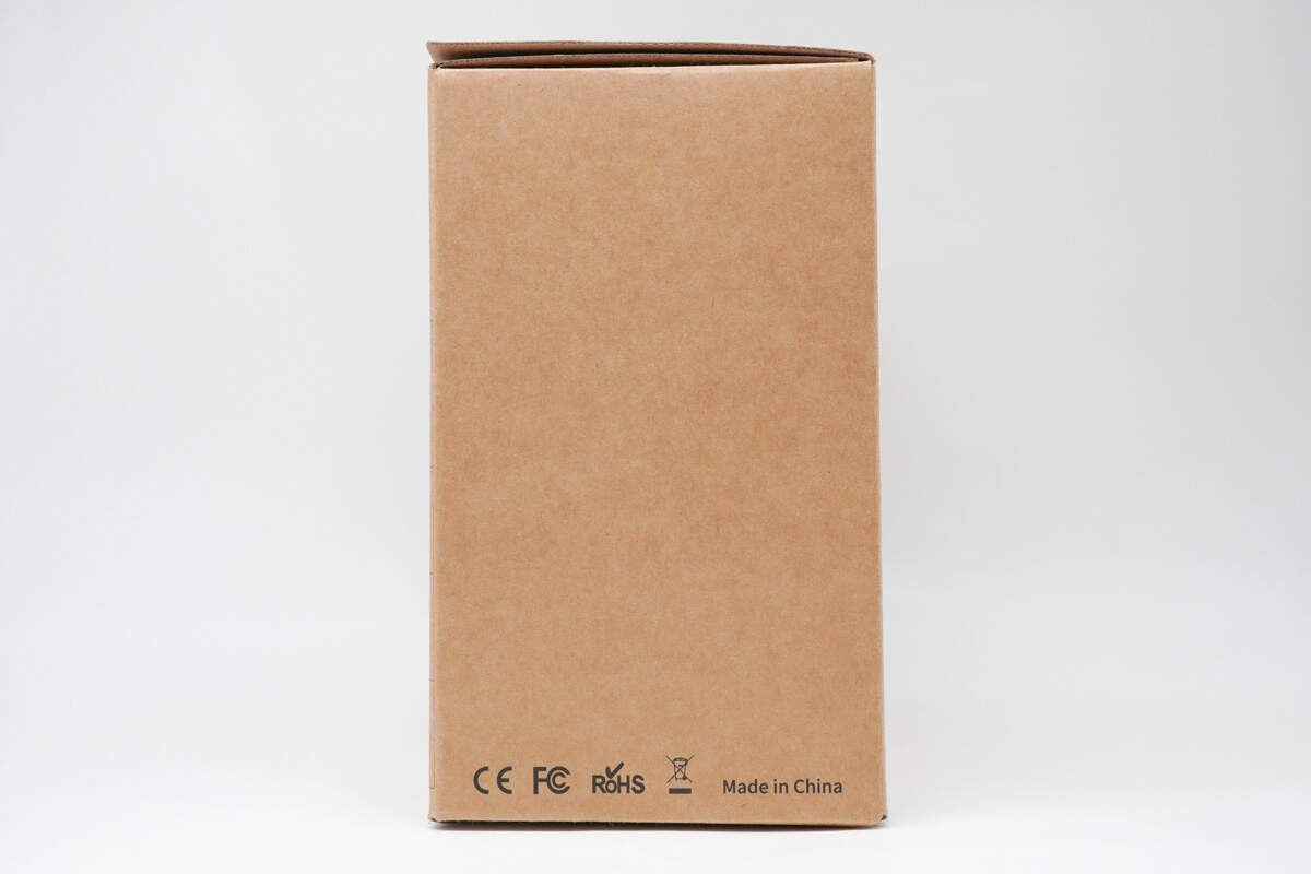
The side features certification marks such as CE, FCC, and RoHS.

The back of the packaging illustrates the application scenarios and compatible devices, and also showcases its support for solar panel charging.
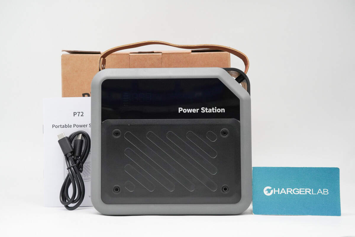
The package includes the power bank, a cable, and some documents.
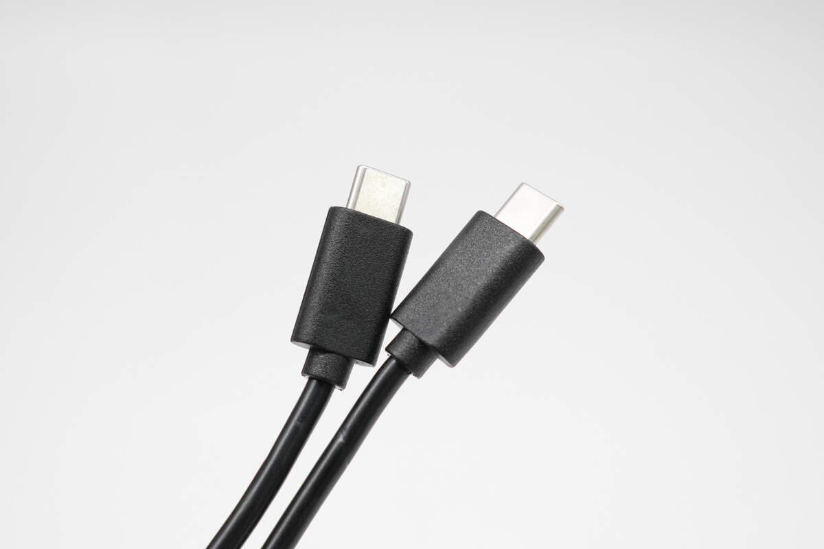
The cable is a dual USB-C type.
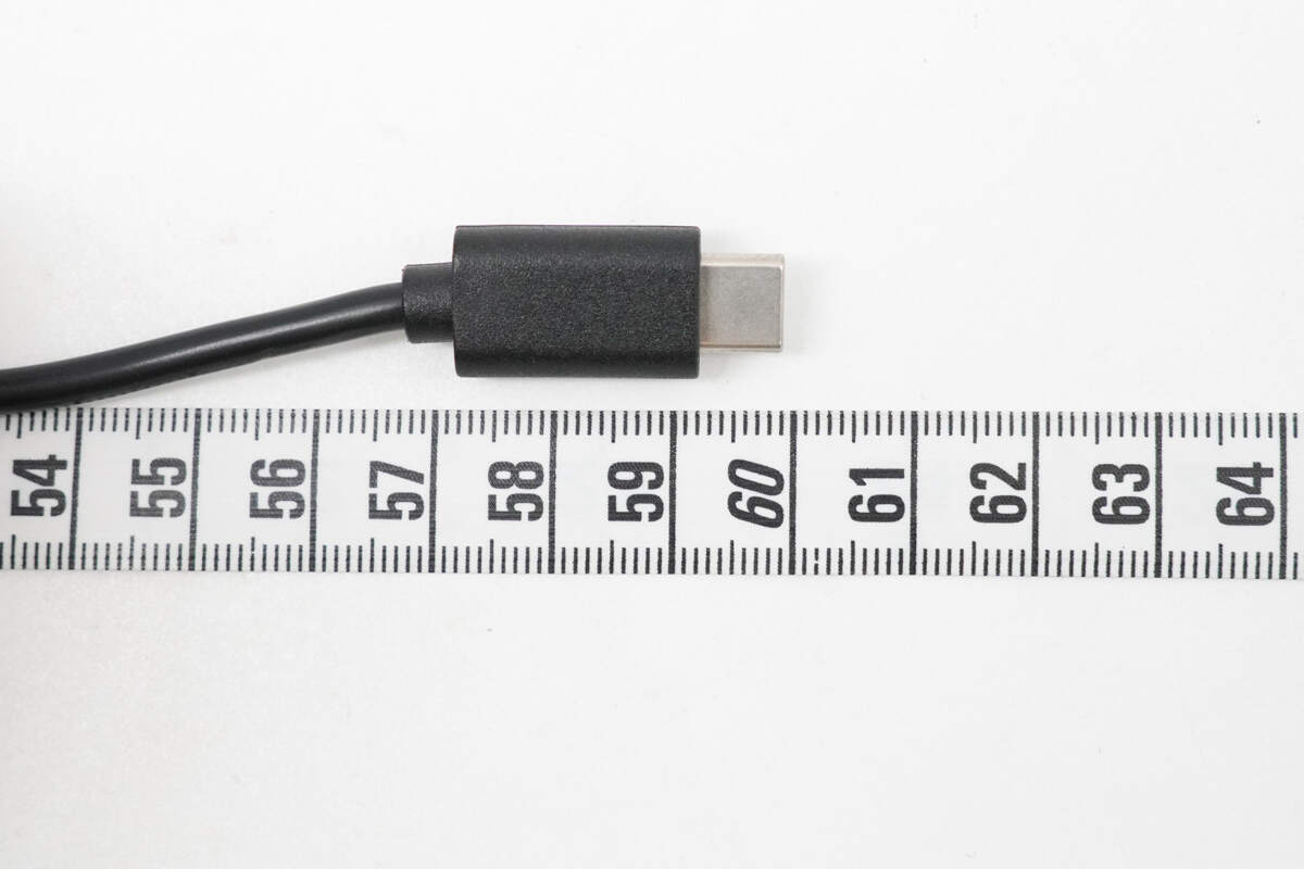
The length is about 60 cm (23.62 inches).
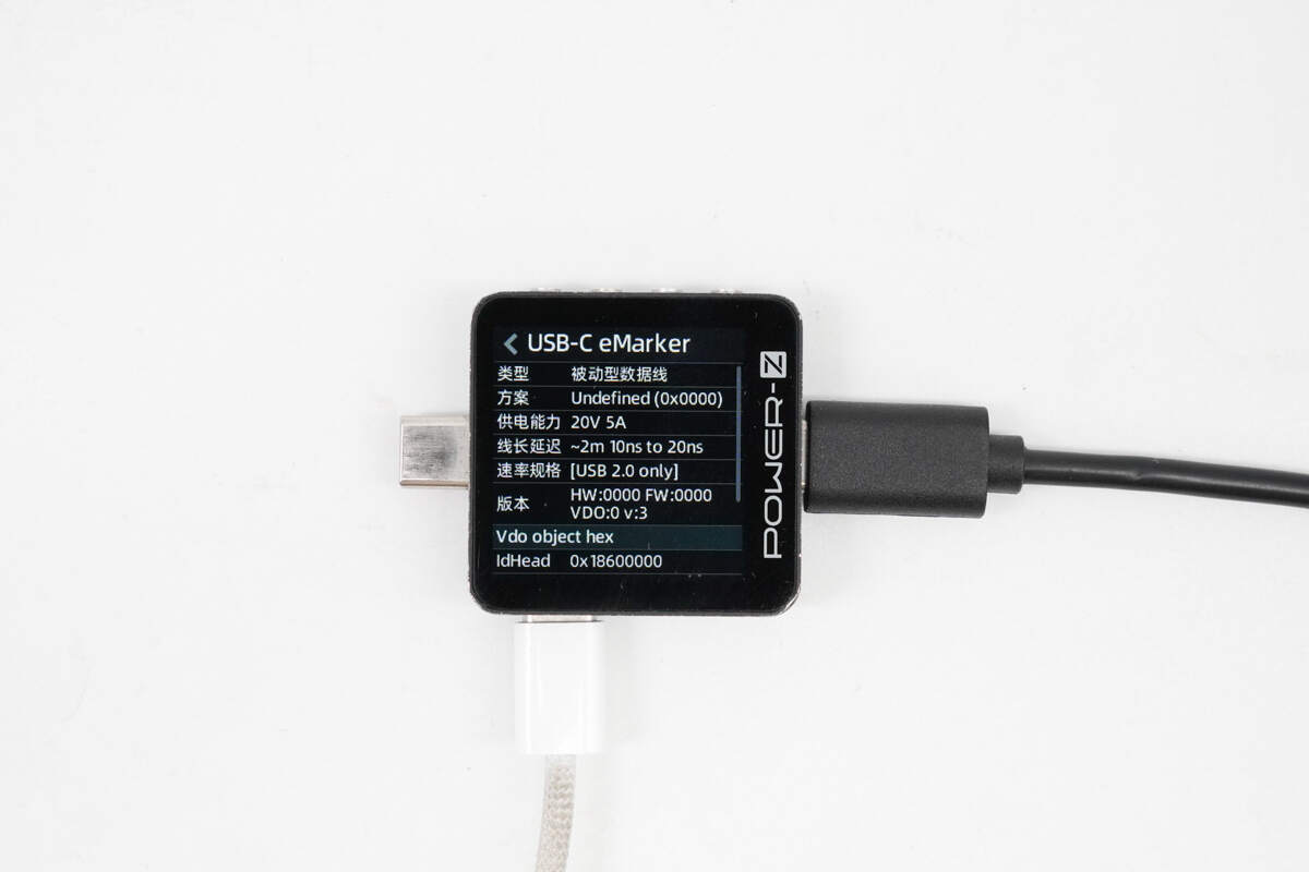
ChargerLAB POWER-Z KM003C shows that the cable has an E-Marker chip, supports power delivery up to 20V/5A, and offers USB 2.0 data transfer capabilities.
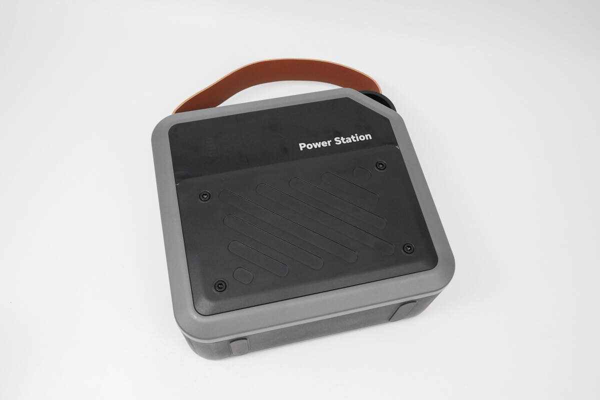
The power station features a black and gray spliced exterior, with four exposed screws on the front that highlight its industrial design style.

The top is equipped with a faux leather handle for easy carrying.
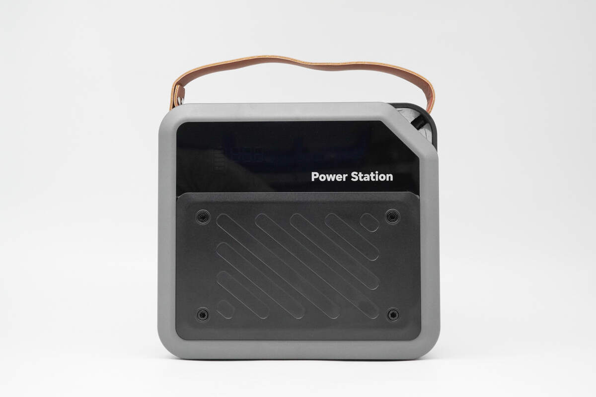
The upper front features an acrylic panel with "Power Station" printed on the lower right corner.
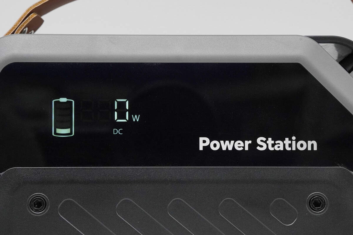
The left side has a built-in digital display that can show the remaining battery level, input/output power, and the charging/discharging ports in use.
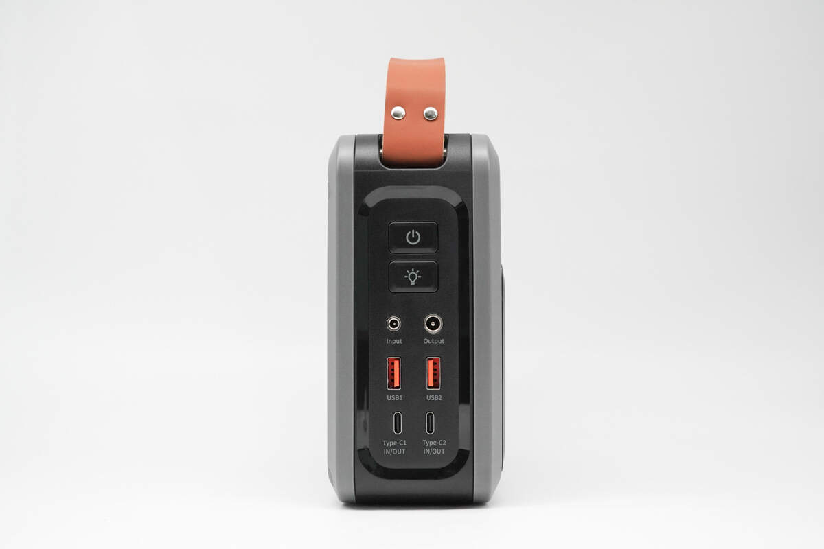
All the buttons and ports are located on one side of the device, set within a recessed area.
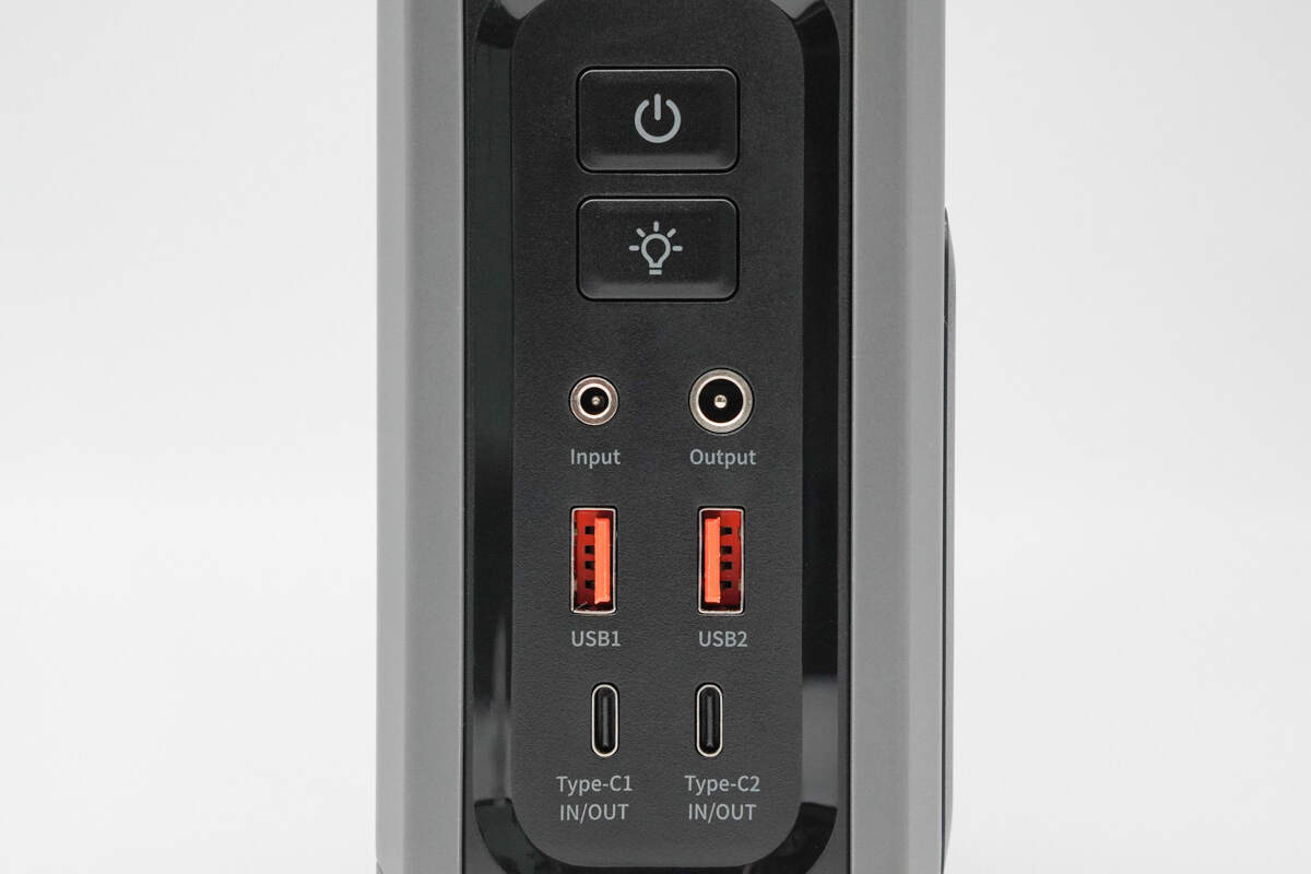
At the top are the power button and LED light button, while the lower section houses the DC input/output ports, two USB-A ports, and two USB-C ports — both of which support 100W PD bi-directional fast charging.
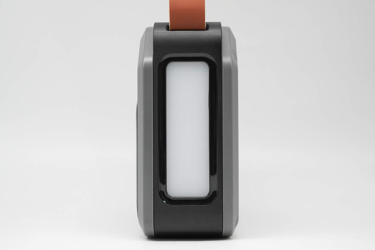
The opposite side features an LED light that supports two brightness levels and four lighting modes: low brightness, constant light, strobe, and SOS.
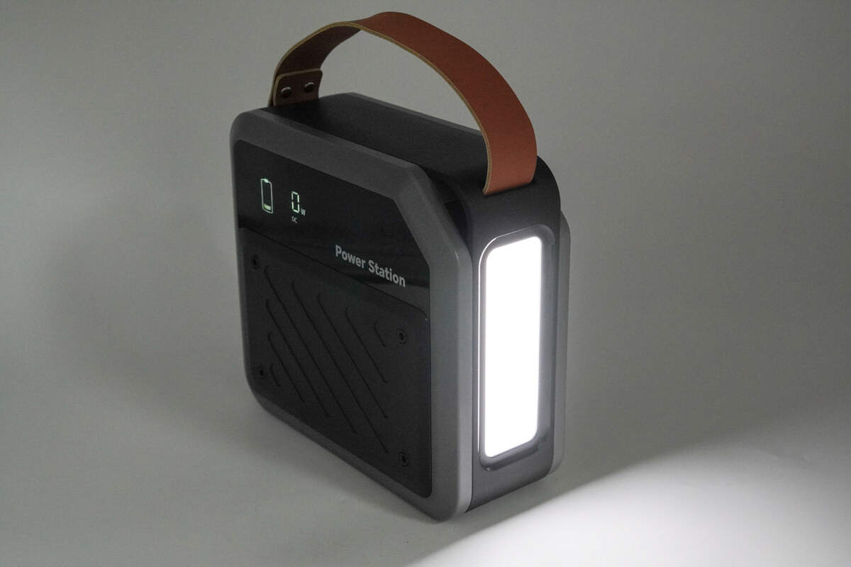
It meets the needs of emergency lighting, distress signaling, and various outdoor activities, greatly enhancing the practicality.
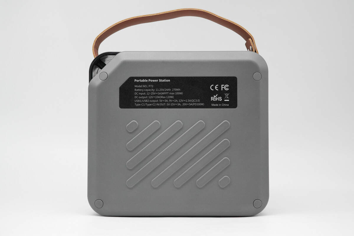
The back features raised anti-slip strips, with a nameplate affixed at the top.
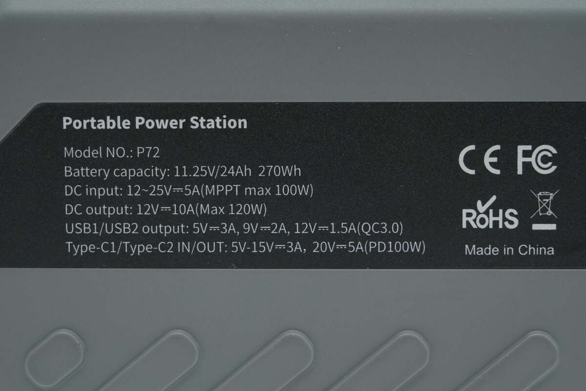
Model: P72
Battery Capacity: 11.25V / 24Ah 270Wh
DC Input: 12–25V / 5A (MPPT max 100W)
DC Output: 12V 10A (Max 120W)
USB-A1/A2 Output: 5V 3A, 9V 2A, 12V 1.5A (QC3.0)
USB-C1/C2 Input/Output: 5–15V 3A, 20V 5A (PD 100W)
It has passed CE, FCC, and RoHS certifications.
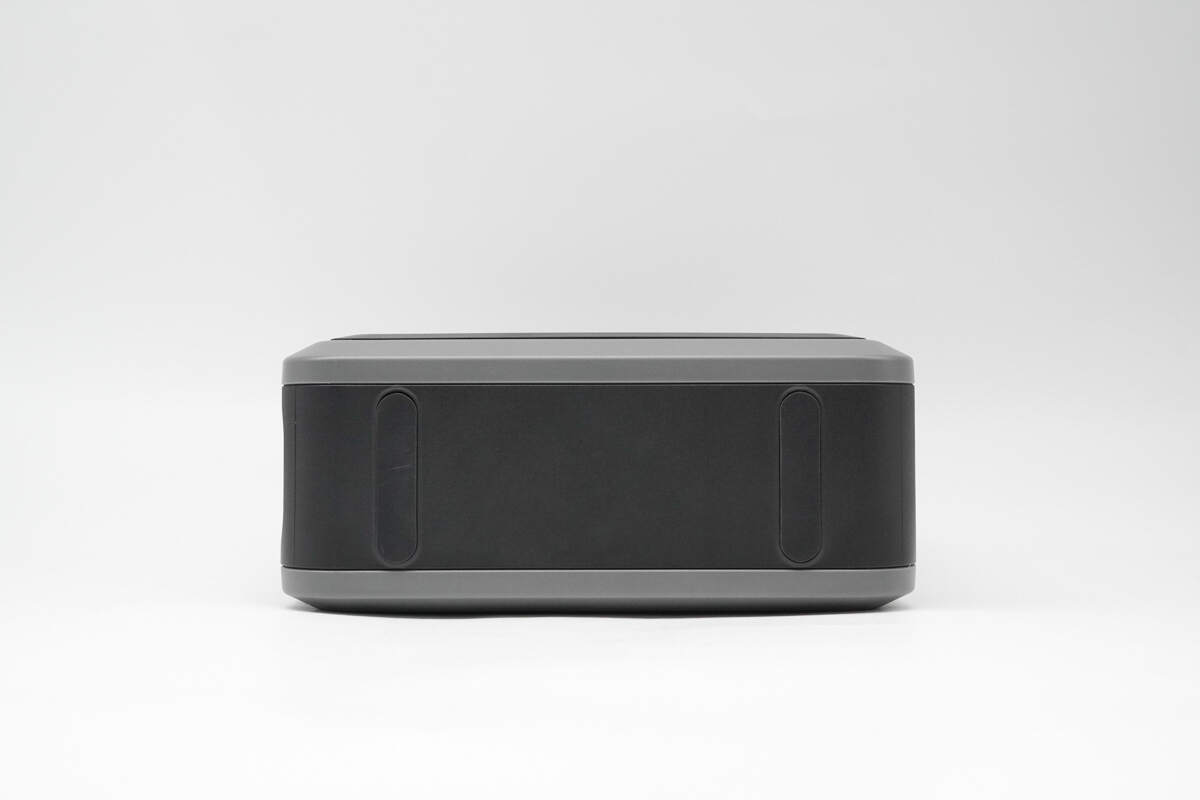
There are anti-slip pads on both sides of the bottom.
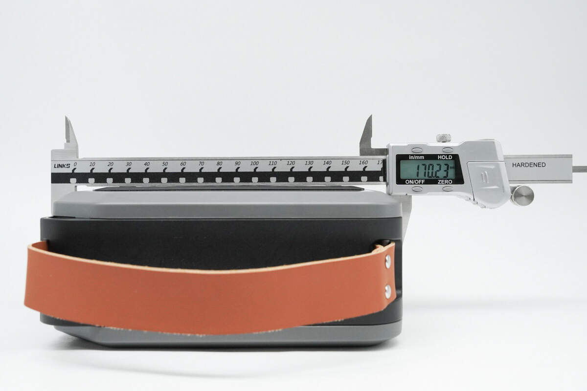
The length of the power station is about 170.23 mm (6.7 inches).
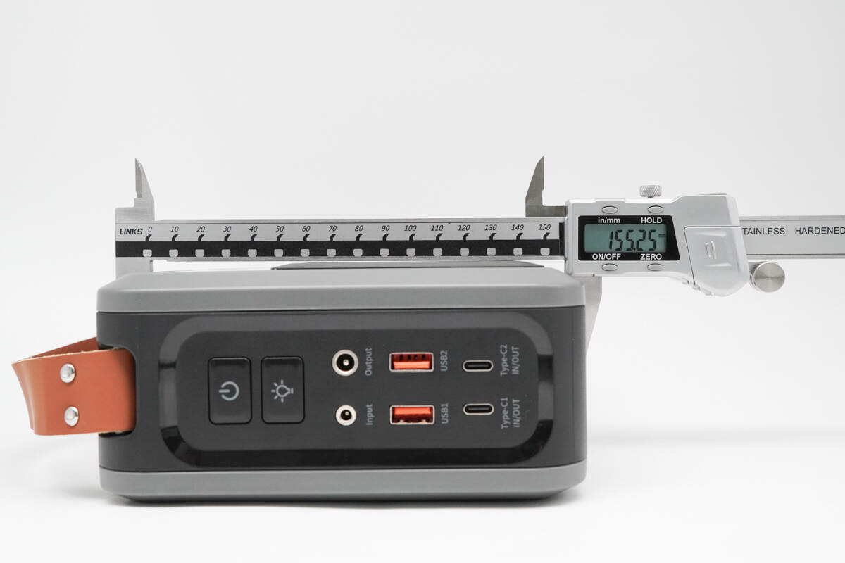
The height is about 155.25 mm (6.11 inches).
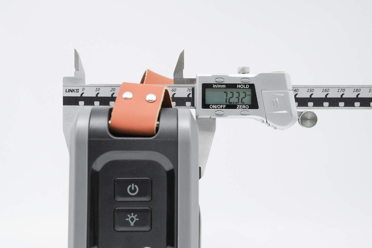
The thickness is about 72.32 mm (2.85 inches).
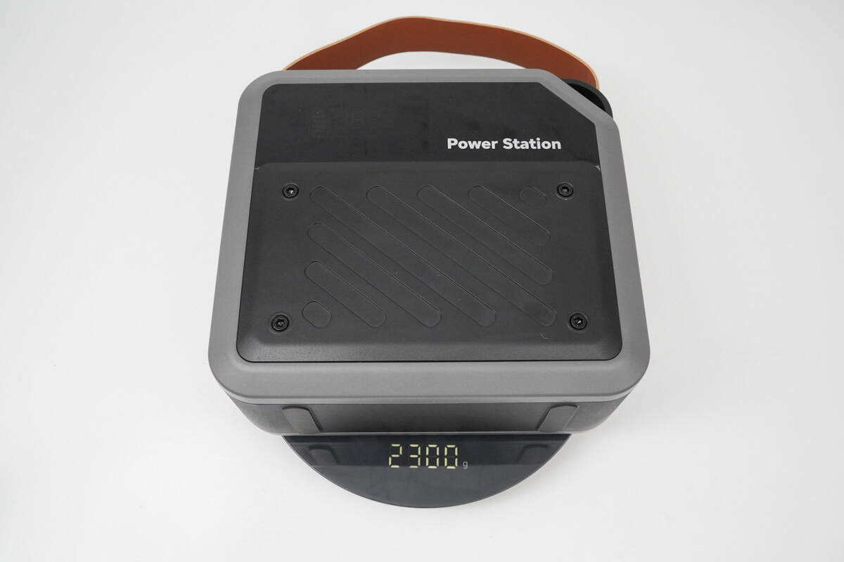
The weight is about 2.3 kg (5.07 pounds).
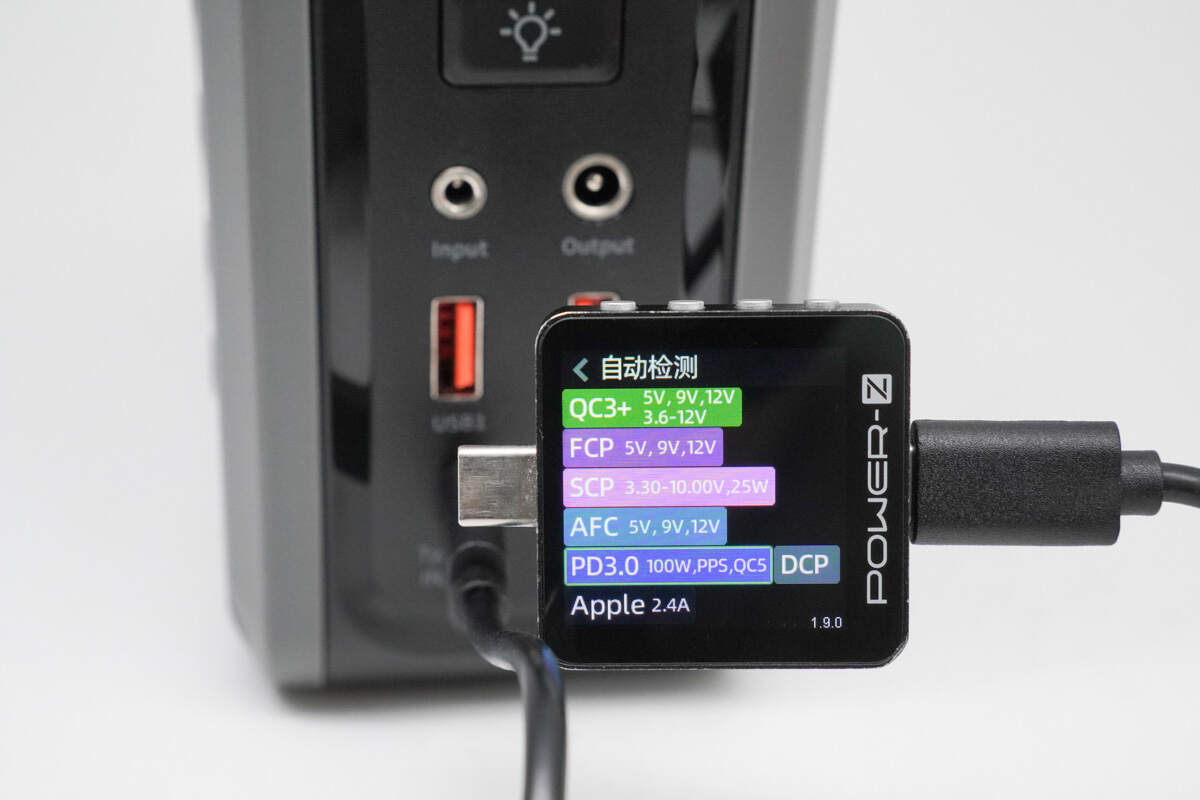
ChargerLAB POWER-Z KM003C shows that the USB-C1 supports QC3.0+/5, FCP, SCP, AFC, PD3.0, PPS, DCP, and Apple 2.4A protocols.
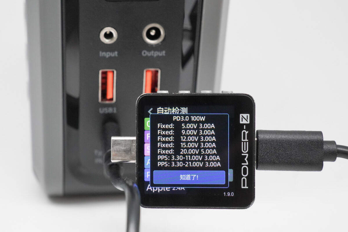
And it has five fixed PDOs of 5V3A, 9V3A, 12V3A, 15V3A, and 20V5A. It has two sets of PPS, which are 3.3-11V3A and 3.3-21V3A.
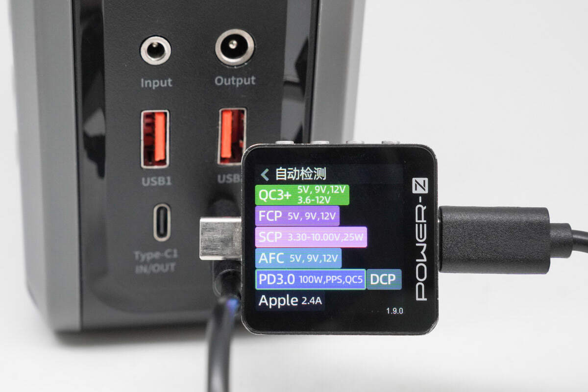
The USB-C2 port supports the same protocols as the USB-C1 port.
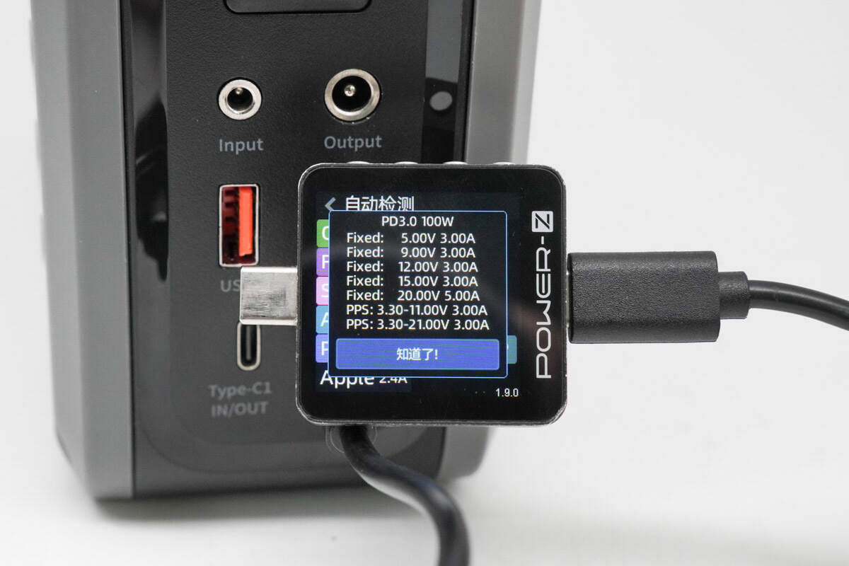
The PDO messages are also identical.
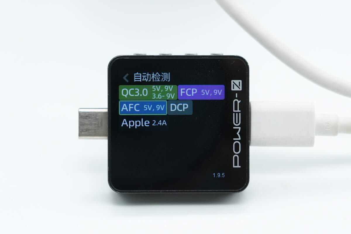
The USB-A1 supports QC3.0, FCP, AFC, DCP, and Apple 2.4A protocols.
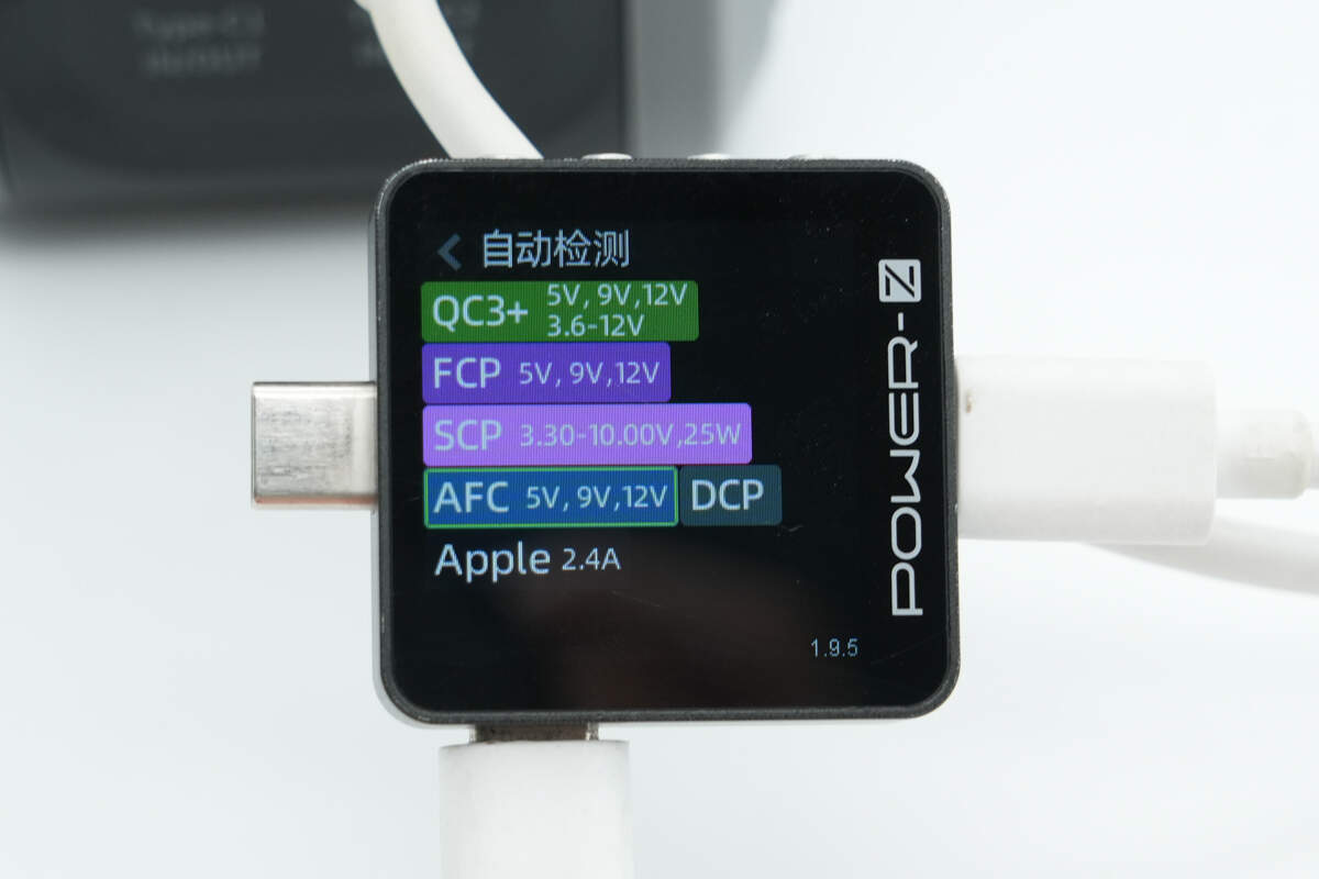
The other USB-A port supports QC3+, FCP, SCP, AFC, DCP, and Apple 2.4A charging protocols.
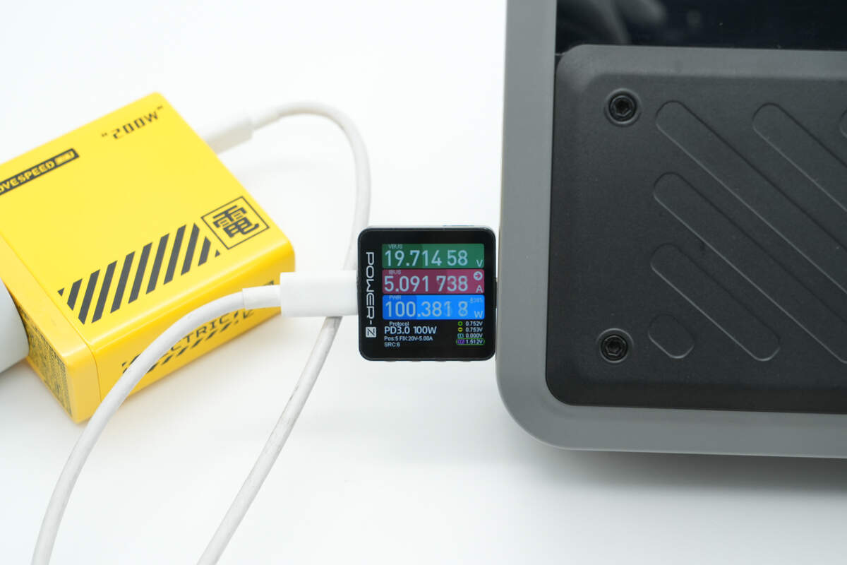
Using the MOVESPEED 140W GaN charger to charge the power station via USB-C, the input power is about 100.38W.
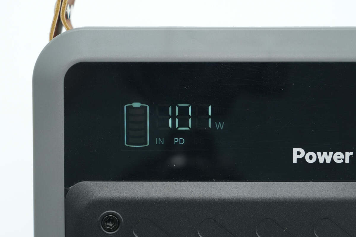
At this time, the digital display shows PD fast charging input and an input power of 101W, which is within the allowable margin of error.
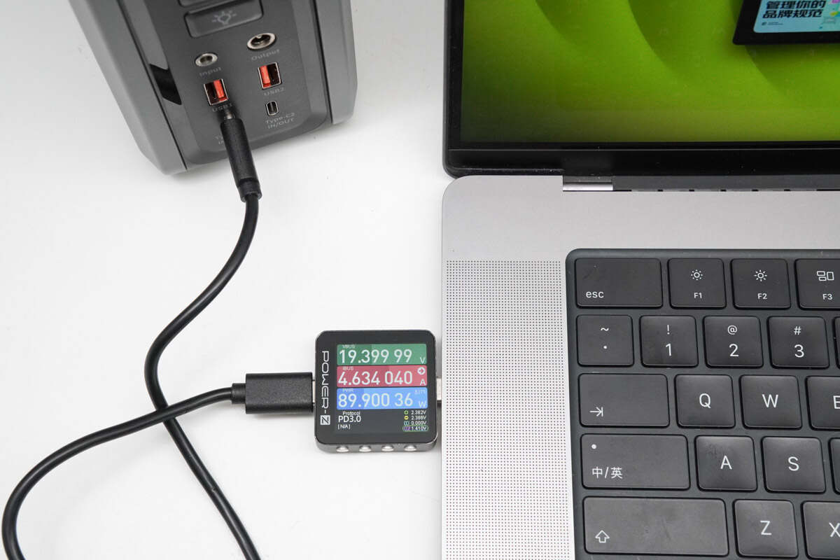
Using the USB-C port to charge a MacBook Pro 16" with M1 Max, the charging power is about 89.9W, successfully activating the 20V 5A 100W PD fast charging.
Teardown
Next, let's take it apart to see its internal components and structure.
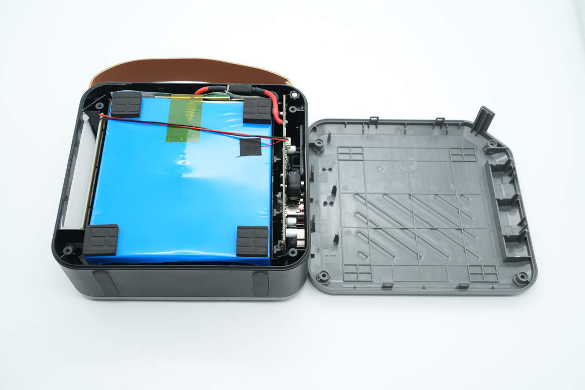
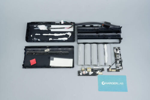
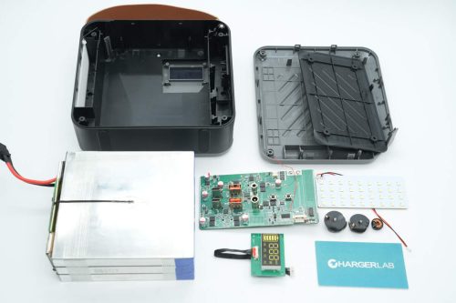
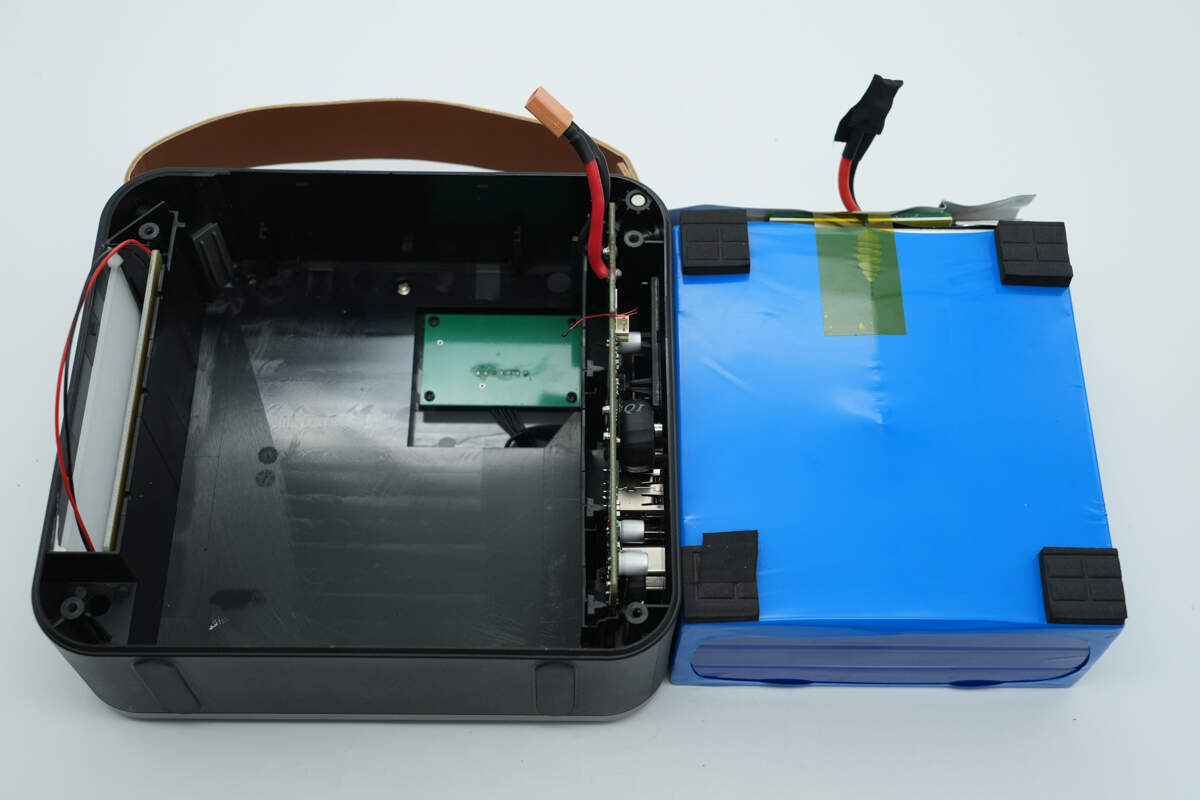
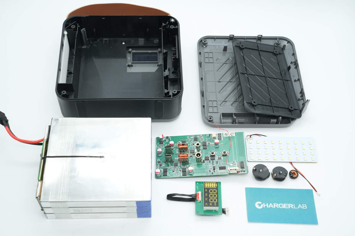
After removing the screws and opening the casing, the battery pack is located in the central area, with PCBs and an LED light board on two sides.
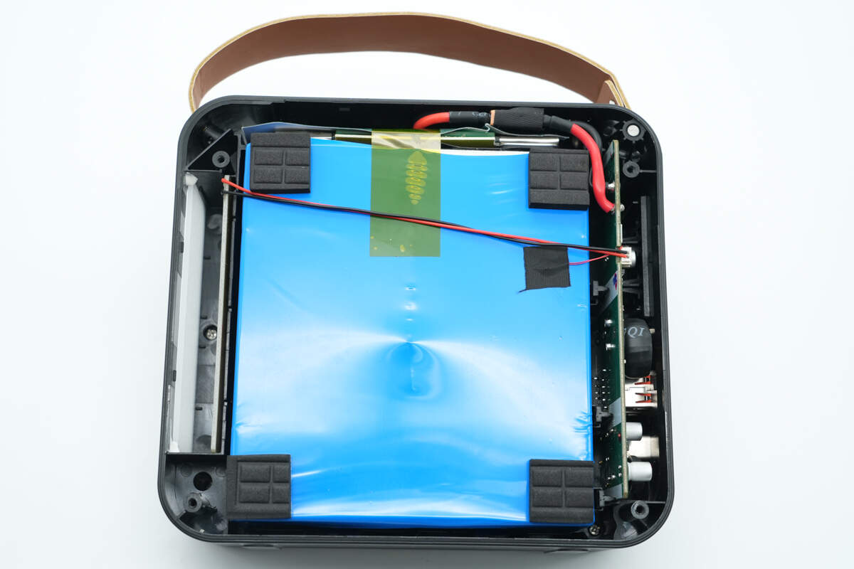
Protective foam is attached to all four ends of the battery pack, and the LED light board is connected to the master control PCB via plug-in wires.
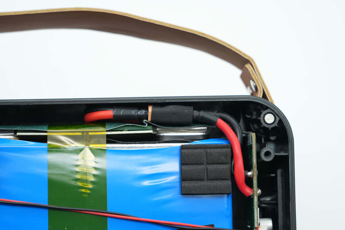
The battery pack is also connected via plug-in wires, with two sets of wires using XT30 connectors, secured with electrical tape.
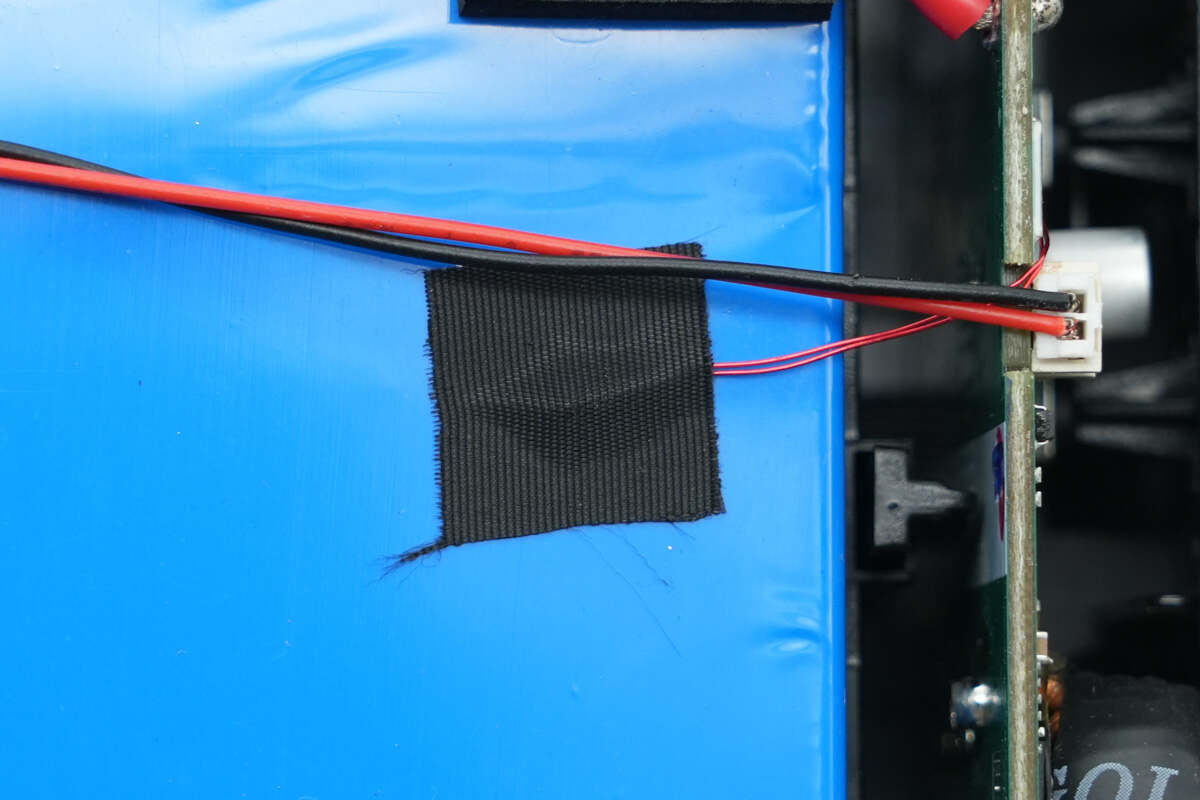
There is also a thermistor for temperature monitoring.
After removing the battery pack, the PCB for the digital display is located underneath. The area features a recessed design to reduce overall thickness.
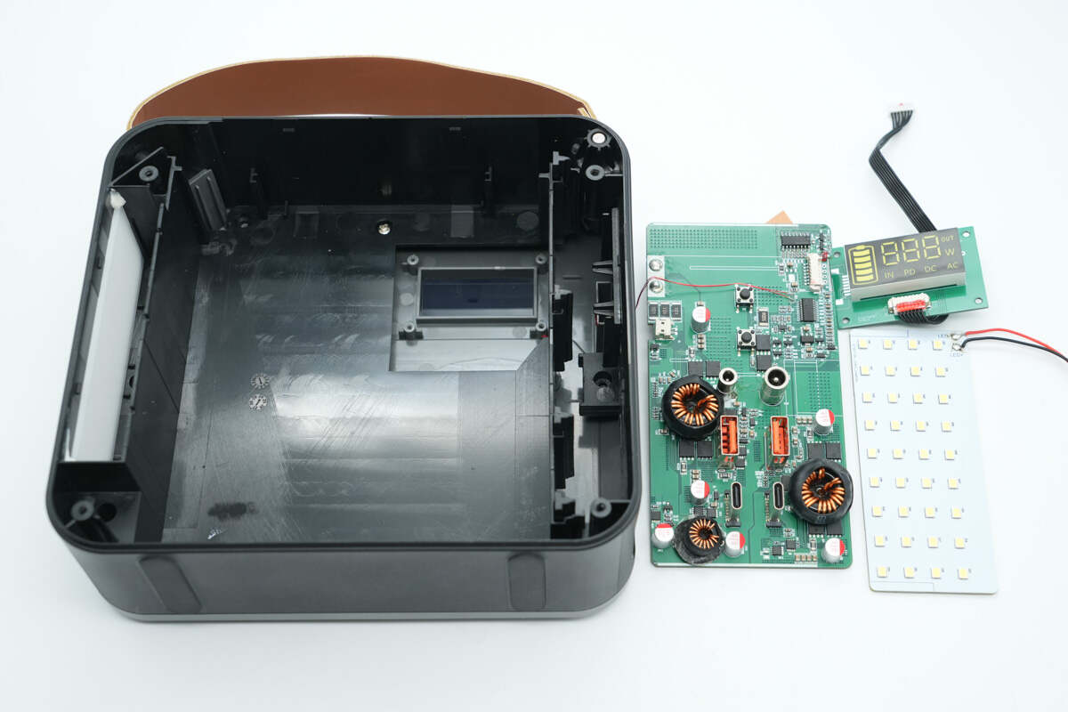
After removing the master control PCB, LED board, and digital display, it is evident that all modules use a plug-in design for easy assembly.
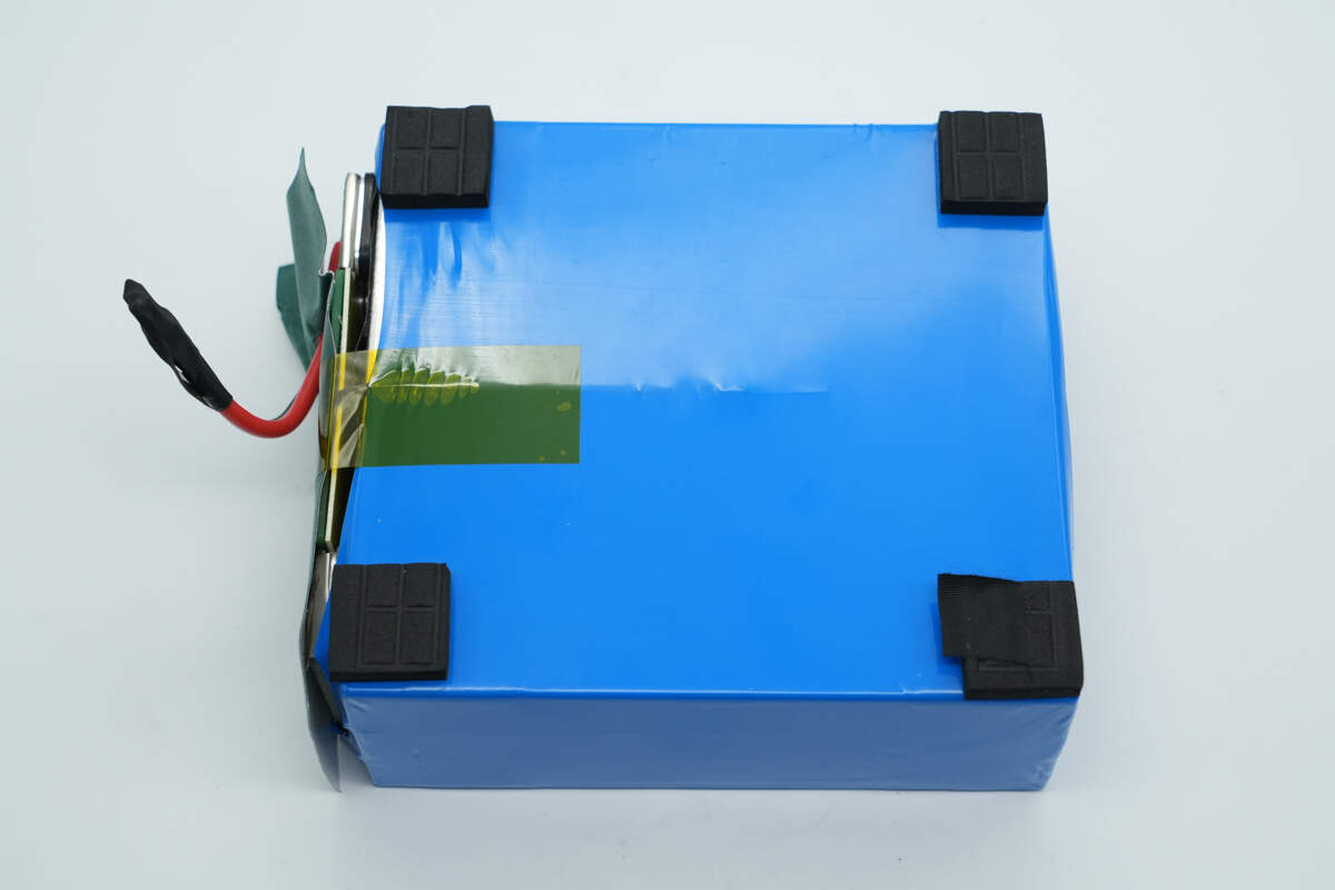
The battery pack is wrapped in blue PVC heat-shrink tubing, with a lithium battery protection PCB located on the left side.
The protection PCB is covered with barley paper and secured with adhesive tape.
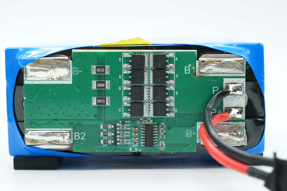
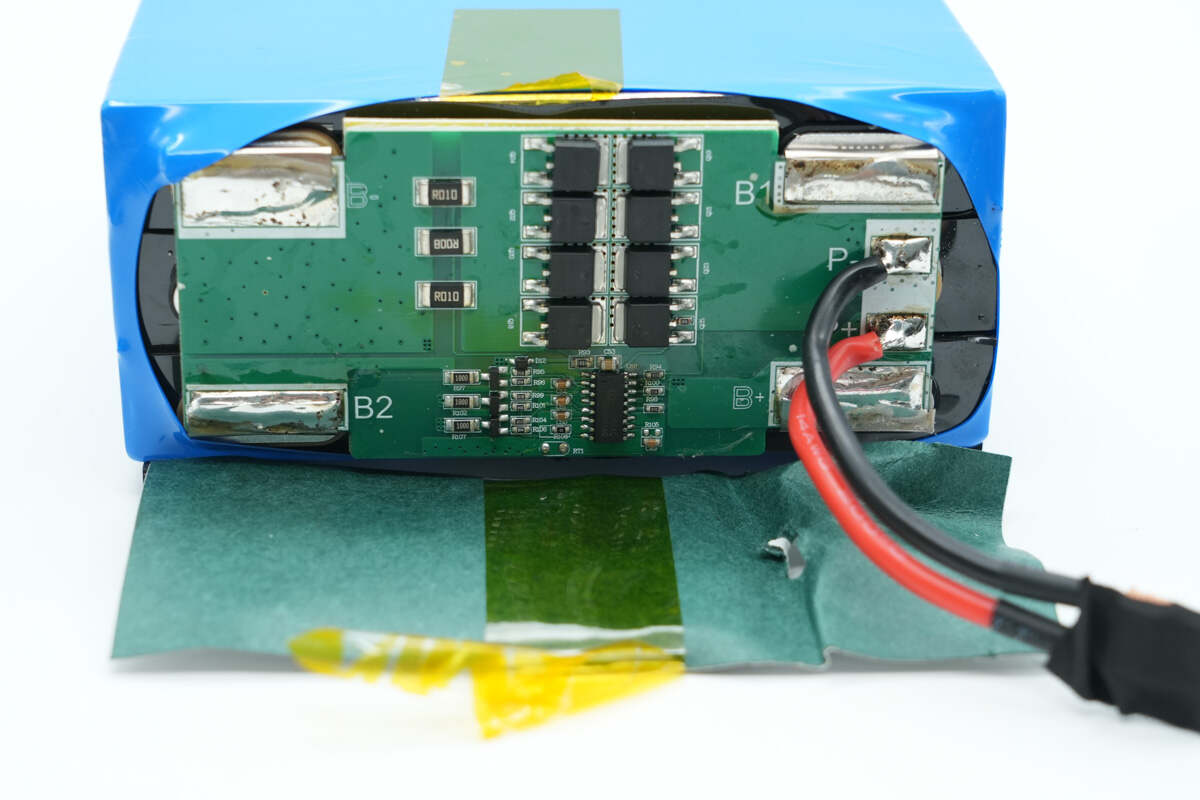
The battery pack and lithium battery protection PCB are connected via nickel strips with auxiliary soldering. The front side of the PCB houses the battery protection chip, battery protection MOSFETs, and the balancing circuit.
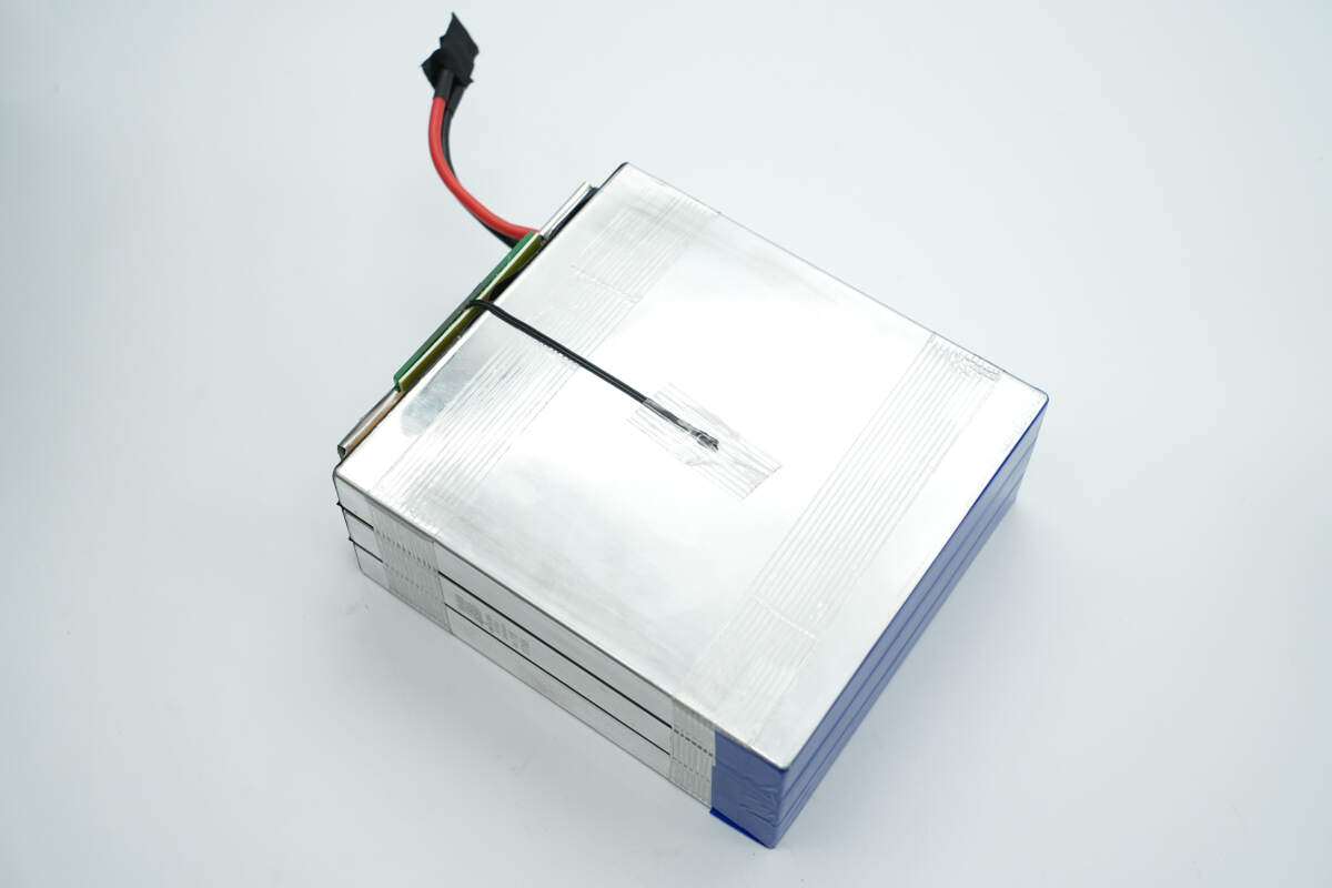
After removing the blue PVC heat-shrink tubing, the battery pack consists of three lithium iron phosphate cells, built using a stacked cell design, with a thermistor attached for temperature monitoring.
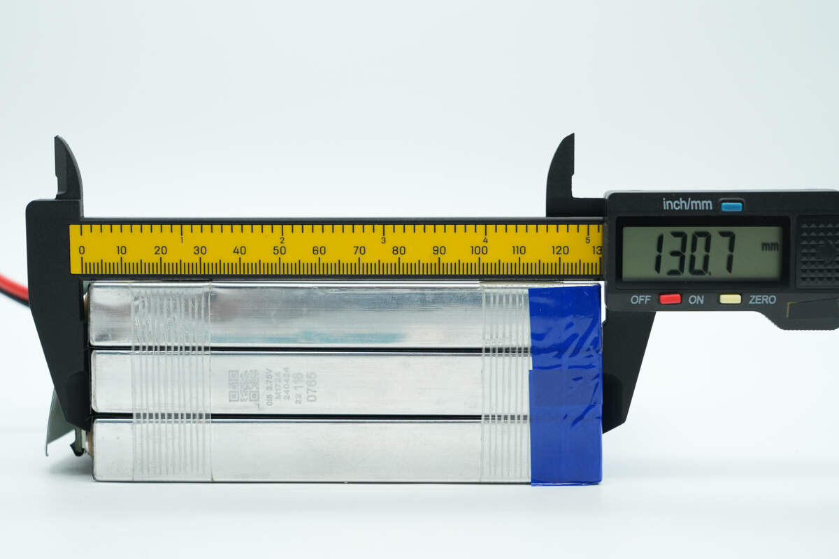
The length of the battery pack is about 130.7 mm (5.15 inches).

The width is about 119.3 mm (4.7 inches).
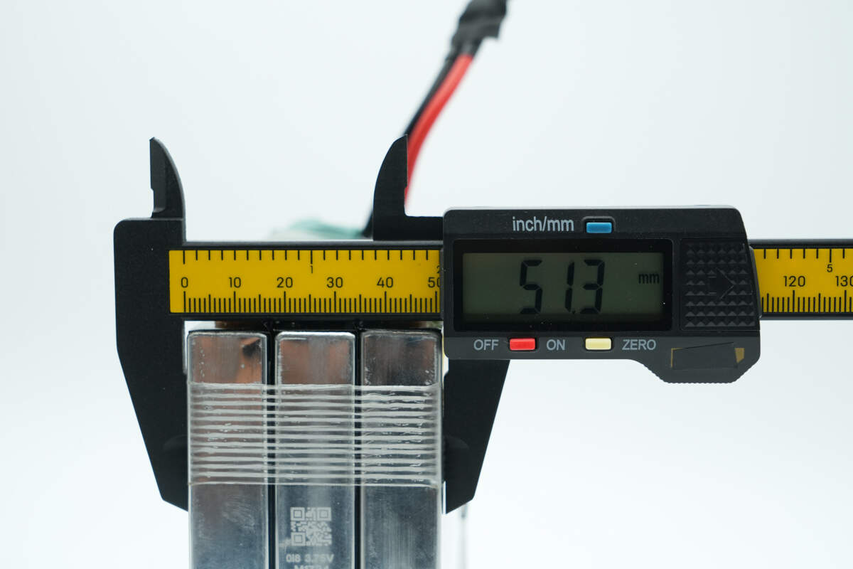
The thickness is about 51.3 mm (2.02 inches).
The weight is about 1767.5 g (3.90 pounds).
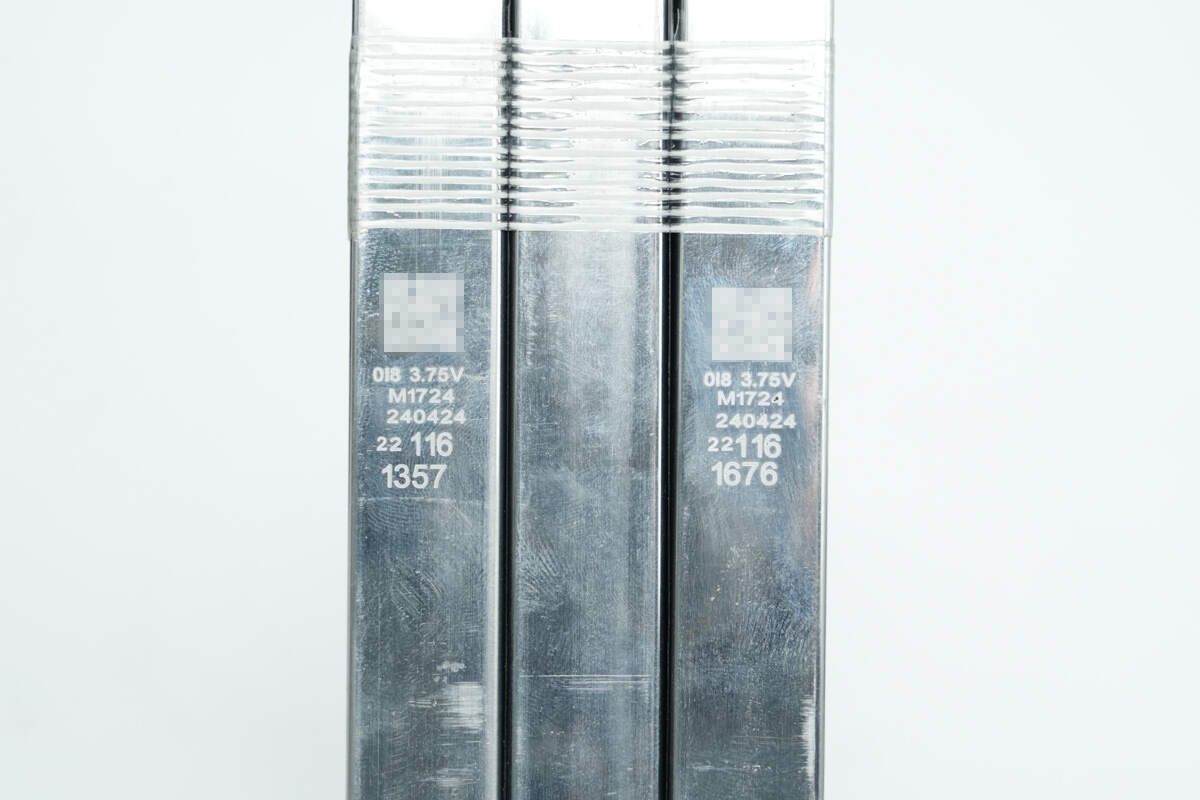
The lithium iron manganese phosphate battery pack is sourced from PHYLION, with a rated capacity of 24Ah, a nominal voltage of 3.75V, a maximum charging voltage of 4.20V, and a maximum discharge current of 24A.
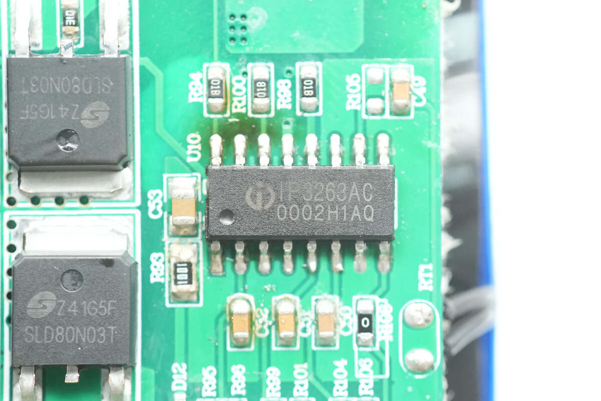
The battery protection chip is the IP3263 from Injoinic. It is a low-power battery pack protector designed as a primary protection solution for 3-cell series lithium-ion/polymer rechargeable batteries. This chip integrates a complete set of voltage, current, and temperature monitoring and protection features required for the safe operation of polymer rechargeable batteries. All protection thresholds and delay times are factory-programmed, with multiple configuration options available to meet different application needs.
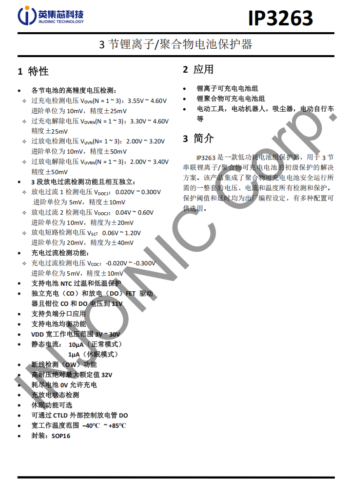
Here is the information about Injoinic IP3263.
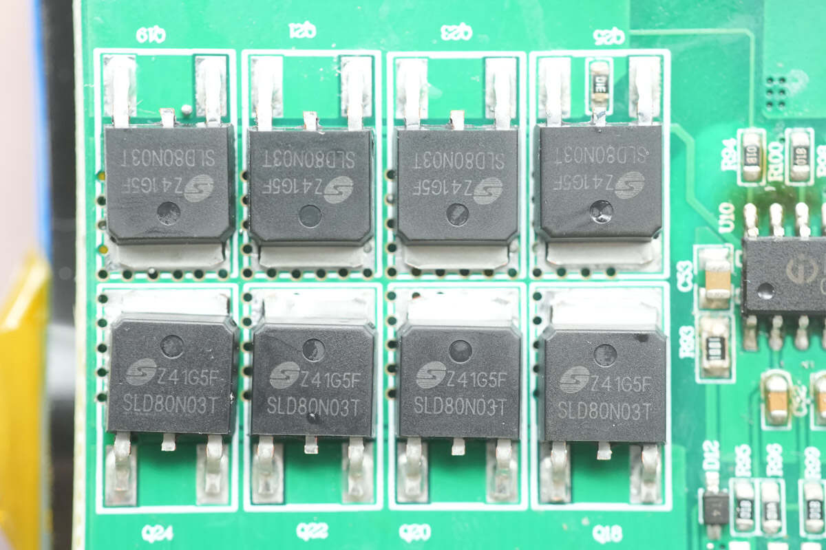
The battery protection MOSFETs are from Msemitek, model SLD80N03T. These are N-channel MOSFETs with a voltage rating of 30V, an on-resistance of 4mΩ, and come in a D-PAK package.
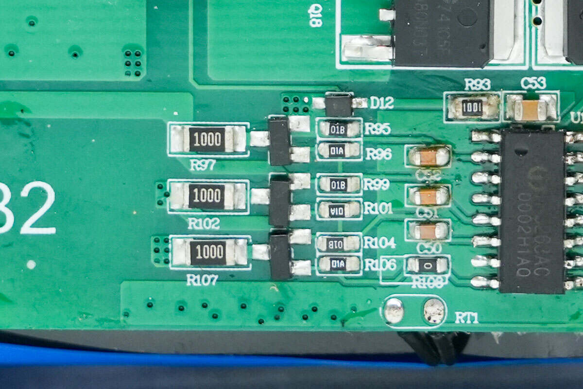
Close-up of the balancing circuit.

Close-up of the thermistor.
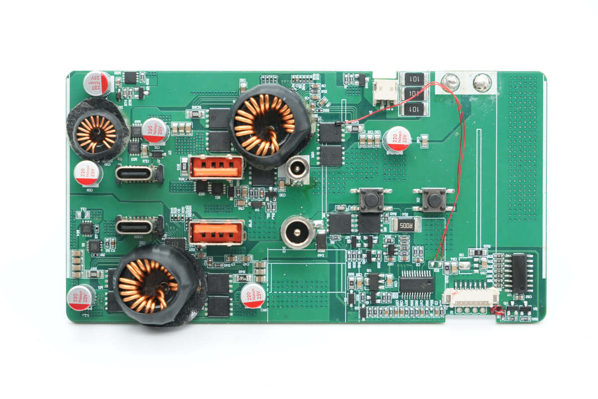
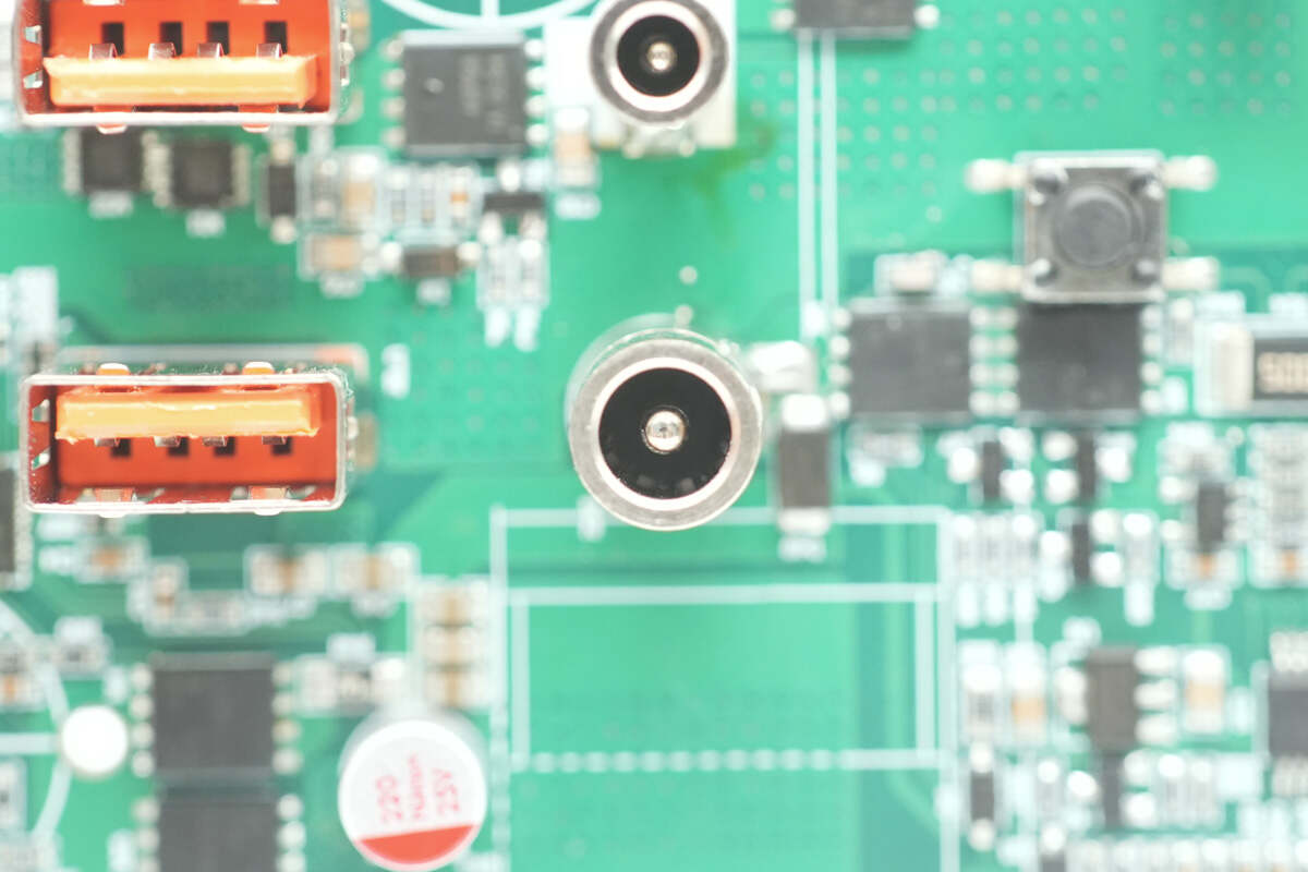
The front side of the master control PCB features components such as a buck-boost SoC, a buck SoC, synchronous buck-boost MOSFETs, buck MOSFETs, inductors, and filter capacitors. It also includes an MCU responsible for driving the LED digital display.
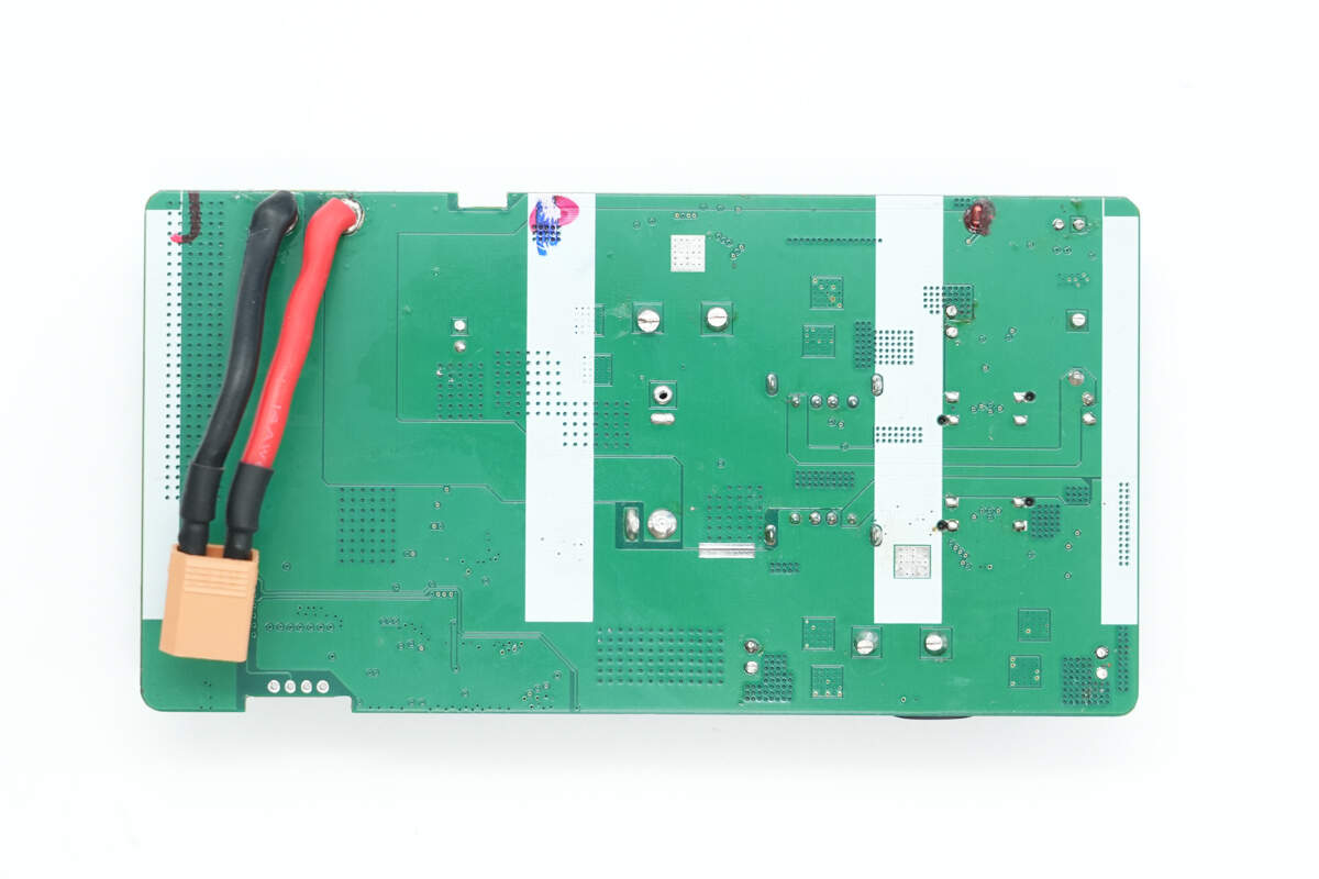
The back only has the connection wires of the battery pack, with no other components present.
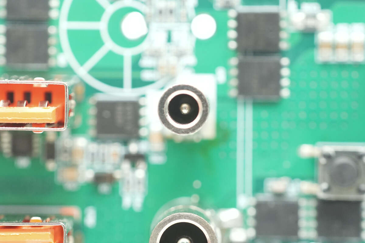
Close-up of the DC input port.
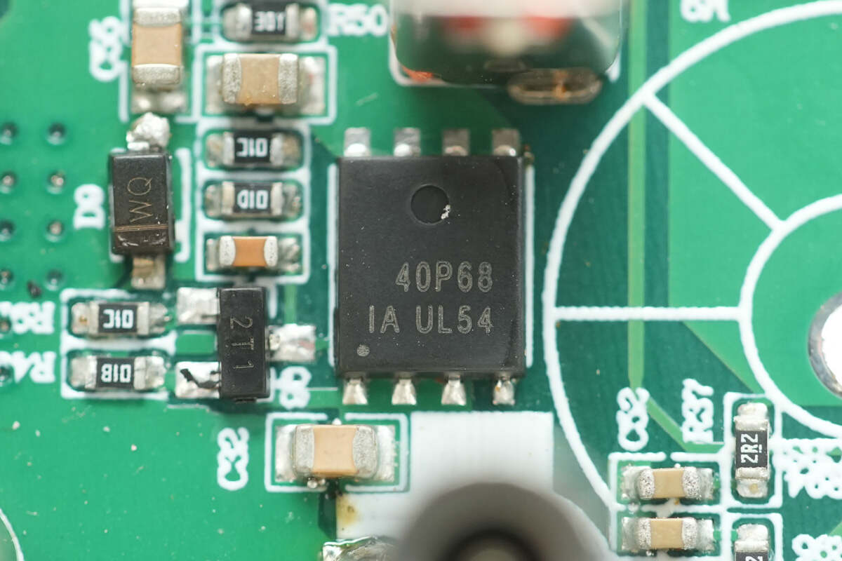
Close-up of the VBUS MOSFET next to the DC input port, marked with "40P68".
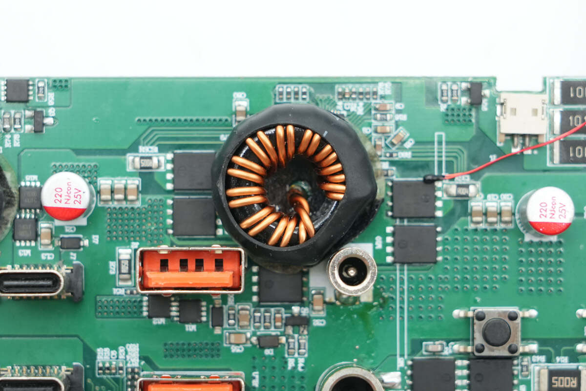
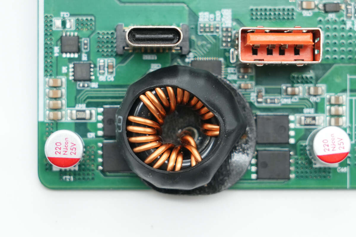
Overview of the circuit used for USB-C1 port charge and discharge management: the inductor is covered with heat-shrink tubing and insulated at the bottom with insulating paper. The circuit also includes the USB-C1 charge/discharge management chip, synchronous buck-boost MOSFETs, and filter capacitors.
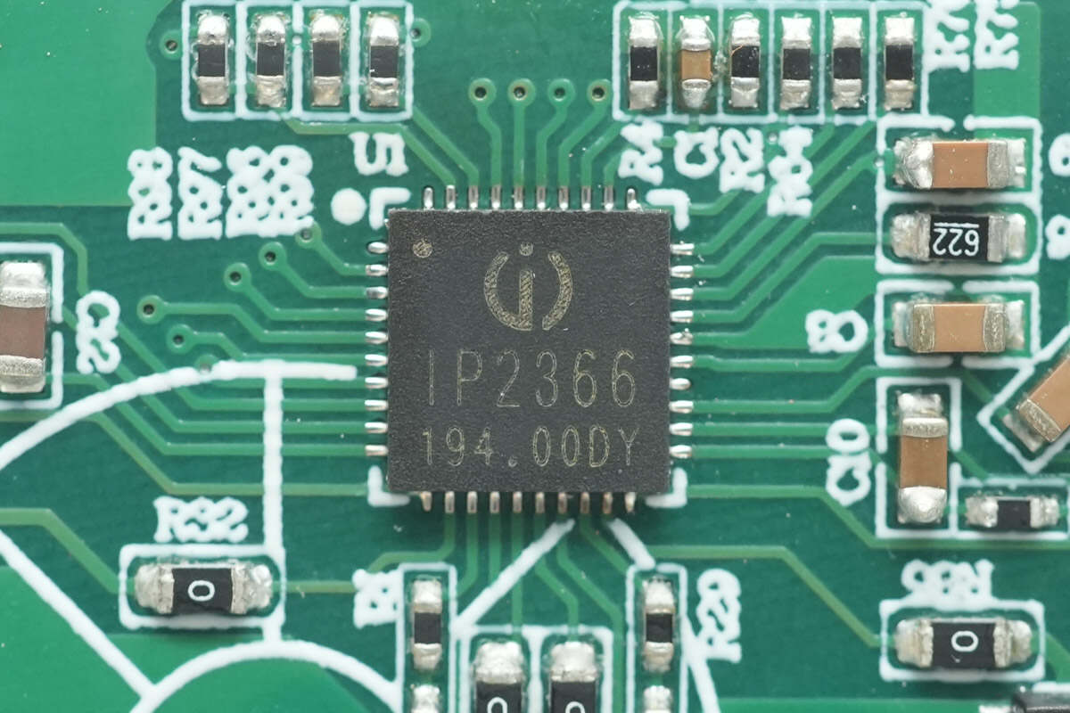
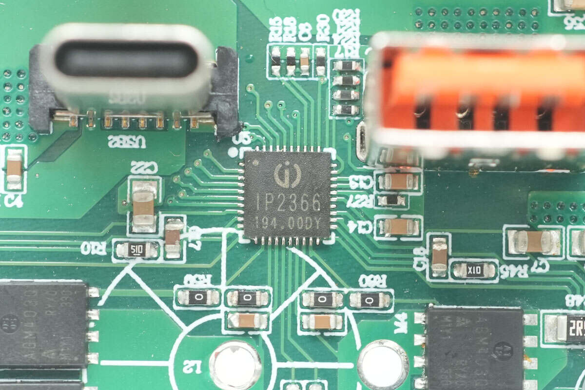
The power management chip for the USB-C1 port is from Injoinic, model IP2366. It is a lithium battery charge and discharge management chip that integrates PD 3.1 and various other fast charging protocols, as well as a bi-directional synchronous buck-boost converter, supporting charging and discharging power up to 140W. Featuring high integration and rich functionality, it achieves synchronous buck-boost operation with just a single inductor and requires very few external components in the application, effectively reducing the overall solution size and lowering BOM costs.

The IP2366 supports 2 to 6 series-connected battery cells and allows configuration of cell count and battery type via external resistors. It supports full-charge voltages of 3.65V, 4.1V, 4.2V, 4.35V, and 4.4V. The chip features built-in monitoring loops for internal temperature, battery temperature, and input voltage. It can intelligently adjust the charging current based on the detected charger power, ensuring safe and efficient charging.
The IP2366 supports a low-power mode, reducing standby current to as low as 5 μA. When a charger is plugged in, the chip automatically wakes up and begins charging. To initiate discharging, a short press of the button is required to wake the system. It features a built-in 14-bit ADC, enabling accurate measurement of input voltage and current, as well as battery voltage and current. Charge and discharge data, such as voltage and current, can be accessed via the I²C interface.
The IP2366 comes in a compact 5 × 5 mm QFN40 package with a 0.4 mm pitch. It offers comprehensive protection features, including input overvoltage and undervoltage protection, output overcurrent and short-circuit protection, battery overcharge, over-discharge, and overcurrent protection, chip over-temperature protection, and NTC-based battery temperature protection. Both CC1 and CC2 pins support up to 30 V withstand voltage, effectively preventing product damage and ensuring high reliability.
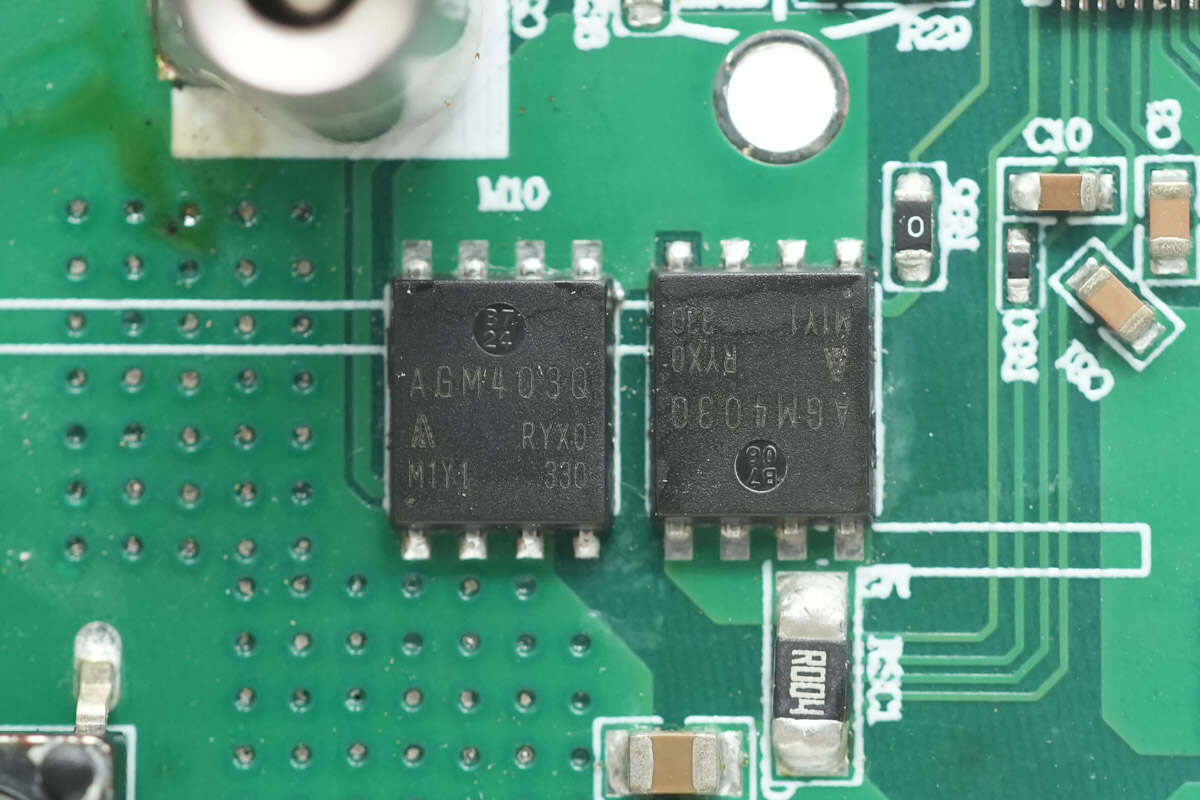
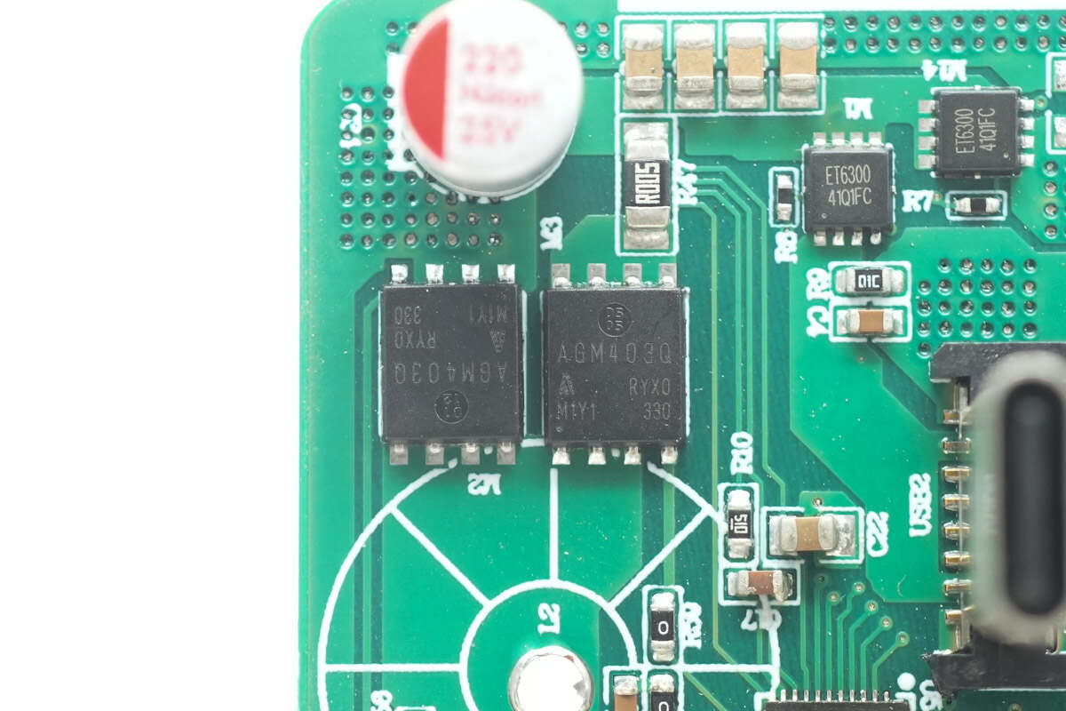
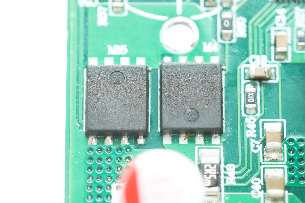
The four paired synchronous buck-boost MOSFETs are from AGMsemi, model AGM403Q. They have a voltage rating of 40V, an on-resistance of 2.8mΩ, and come in a PDFN 5×6 package.
Close-up of the other two MOSFETs.
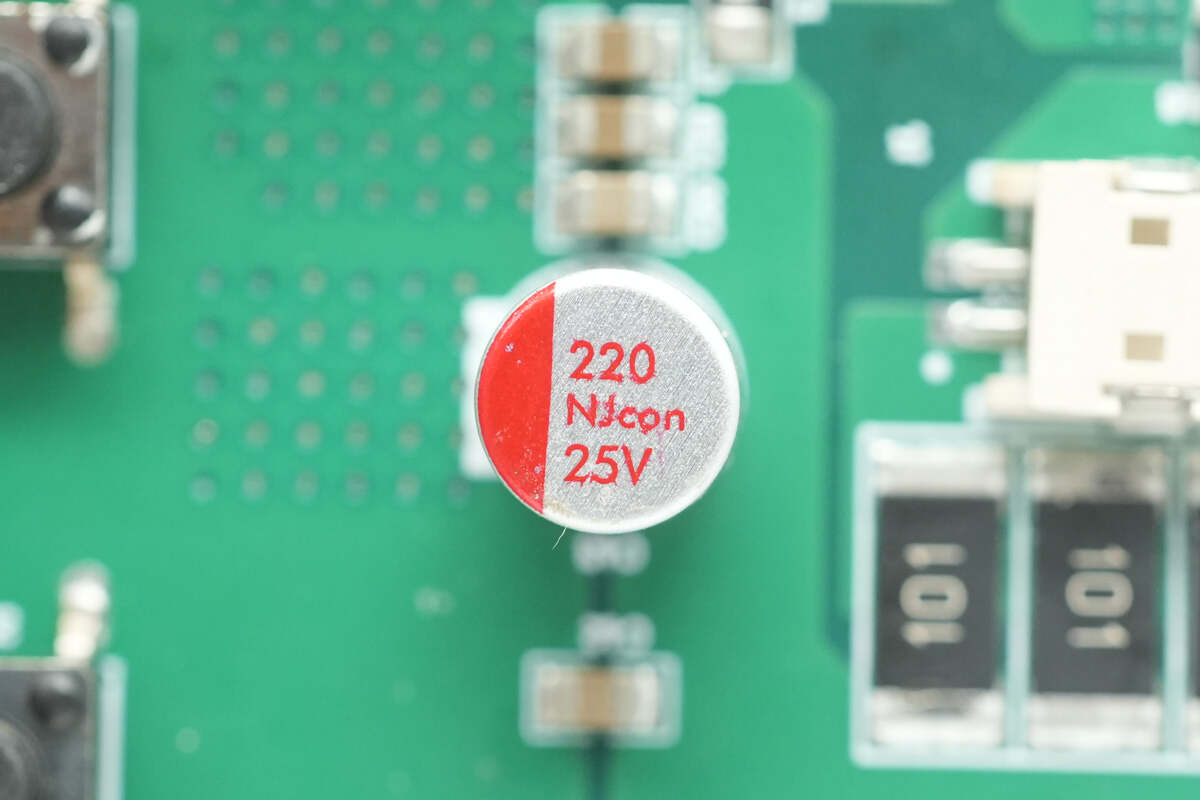
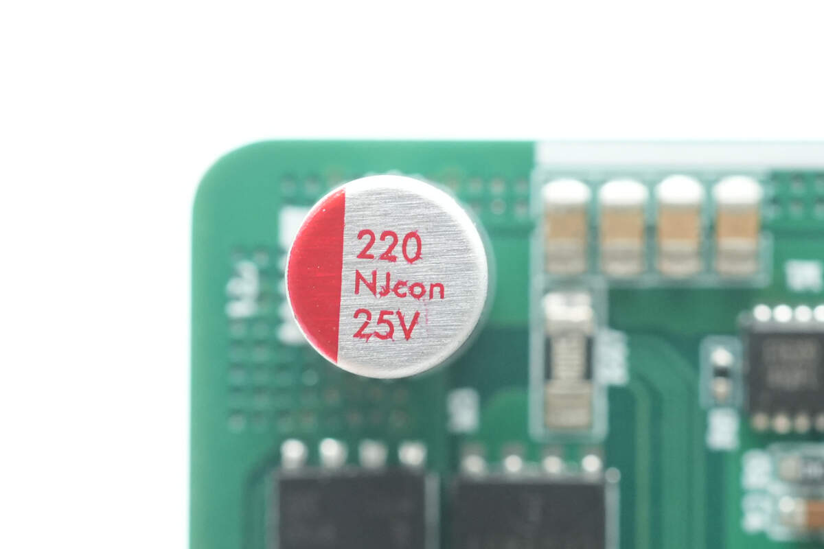
The solid capacitor used on the battery side is from NJcon, with a specification of 25V 220μF.
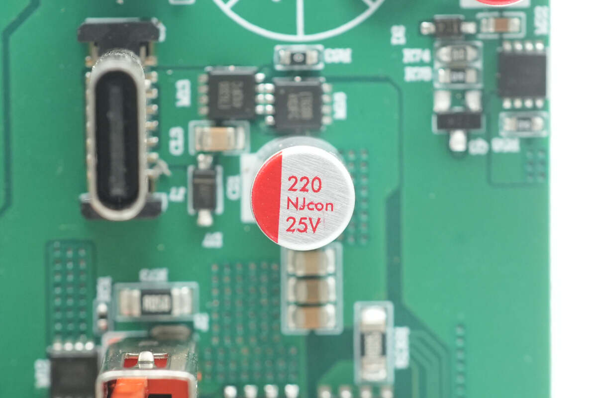
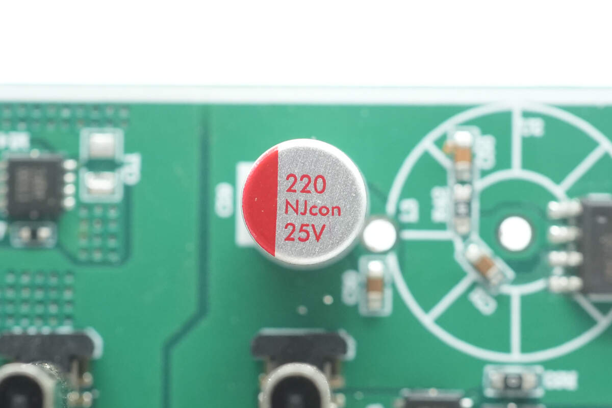
The solid capacitor used for the USB-C1 port is from NJcon, with a specification of 25V 220μF.
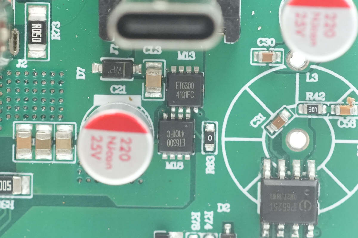
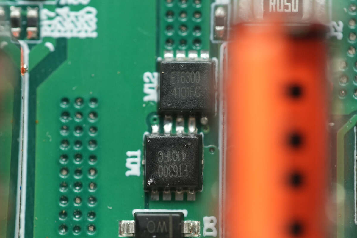
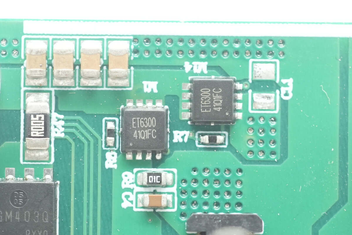
The two VBUS MOSFETs for the USB-C1 port are marked with ET6300 and use a PDFN 3.3×3.3 package.
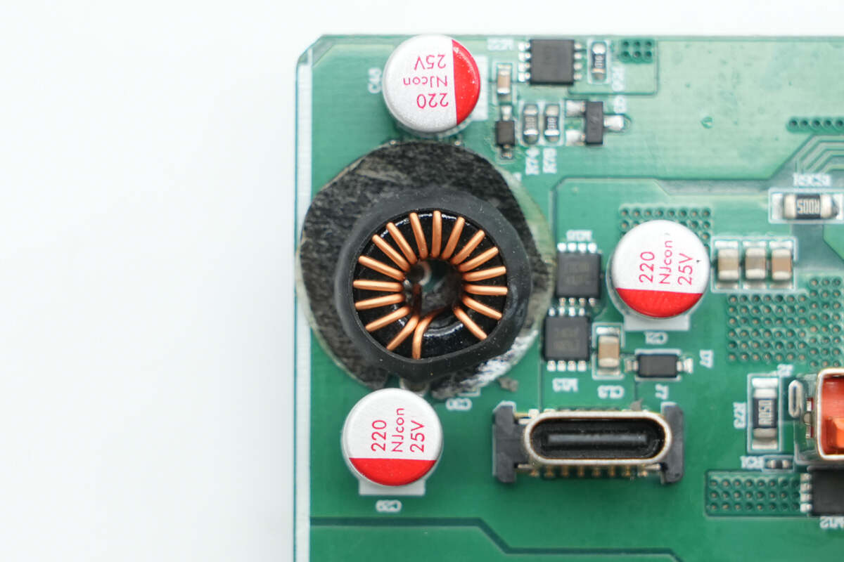
Overview of the buck output circuit for the USB-A1 port: the inductor is wrapped with heat-shrink tubing and insulated at the bottom with insulating paper. Beneath and around the inductor are the synchronous buck SoC for the USB-A1 port and several solid capacitors.
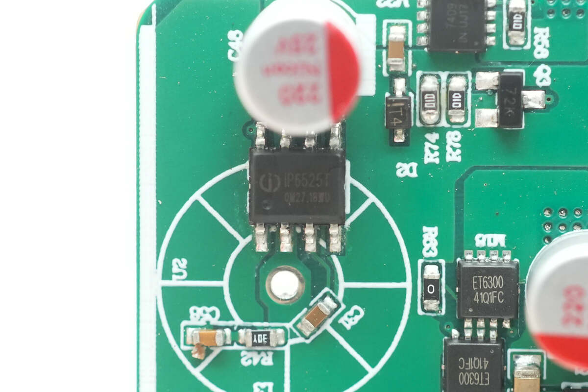
The buck-boost protocol chip for the USB-A1 port is from Injoinic, model IP6525T. It is an integrated synchronous buck converter with built-in power MOSFETs, offering high conversion efficiency—up to 98%. It supports four fast charging protocols and operates with an input voltage range of 9.6V to 32V and an output voltage range of 3V to 12V, delivering up to 18W of output power.
Additionally, it can automatically adjust the output voltage and current based on the detected fast charging protocol. Typical output profiles include 5V/3.4A, 9V/2.0A, and 12V/1.5A, making it a comprehensive solution for car chargers, fast-charging adapters, and smart power strips.
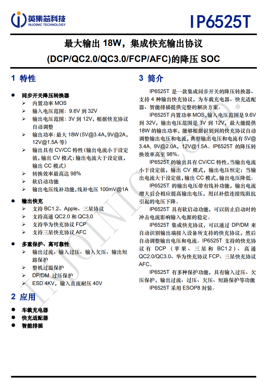
Here is the information about Injoinic IP6525T.
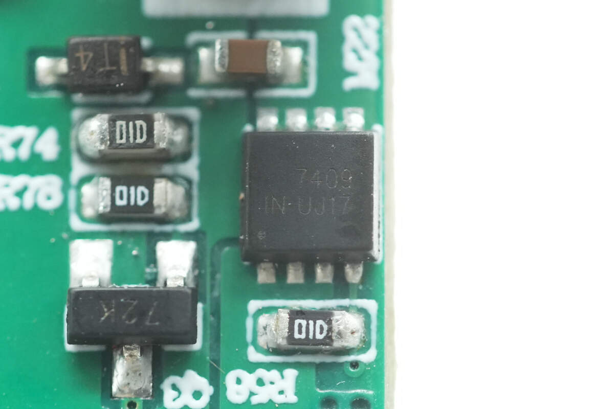
The MOSFET controlling power delivery to the USB-A1 port is marked with "7409".
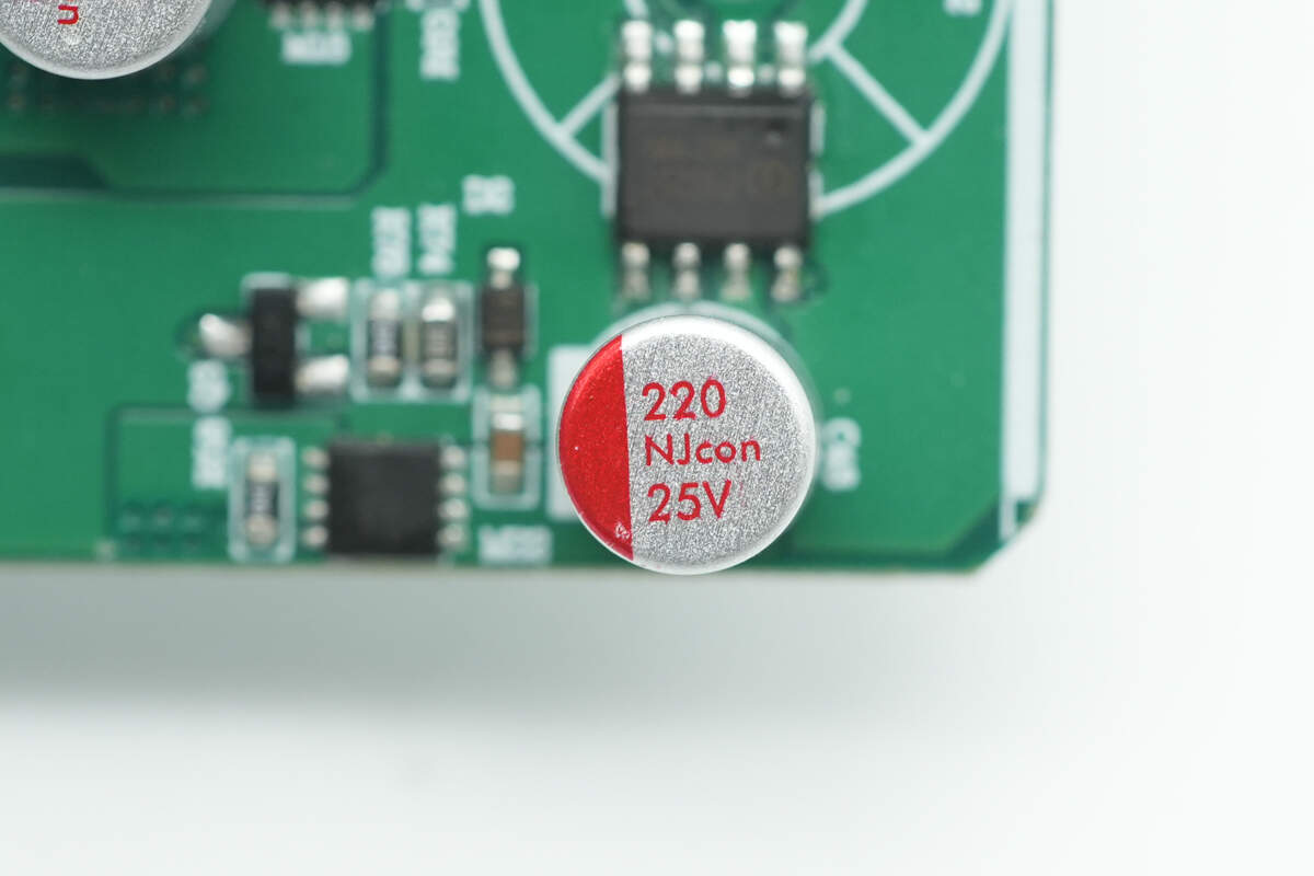
The solid capacitor used for output filtering is also from NJcon, with a specification of 25V 220μF.
The other capacitor has the same model and specifications.
The VBUS MOSFETs for the USB-A1 port share the same part number as those used for the USB-C1 port.
Overview of the charge and discharge management circuit for the USB-C2 and USB-A2 ports: the inductor is wrapped with heat-shrink tubing and insulated at the bottom with insulating paper. Surrounding the inductor are the charge/discharge management chips for both ports, synchronous buck-boost MOSFETs, and solid capacitors.
The power management chip used for the USB-C2 and USB-A2 ports is also the Injoinic IP2366.
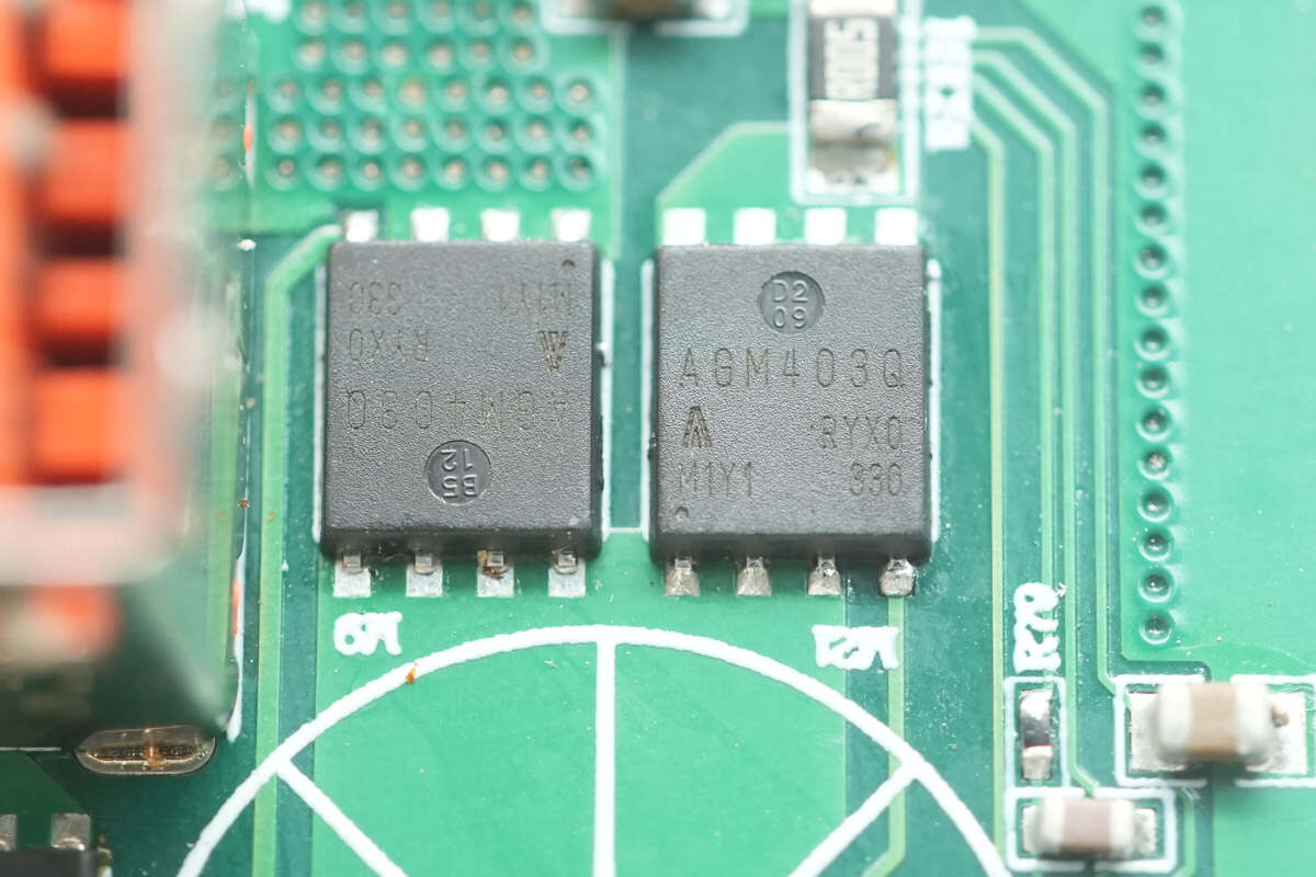
The four synchronous buck-boost MOSFETs paired with them are also AGMsemi AGM403Q.
Close-up of the other two MOSFETs.
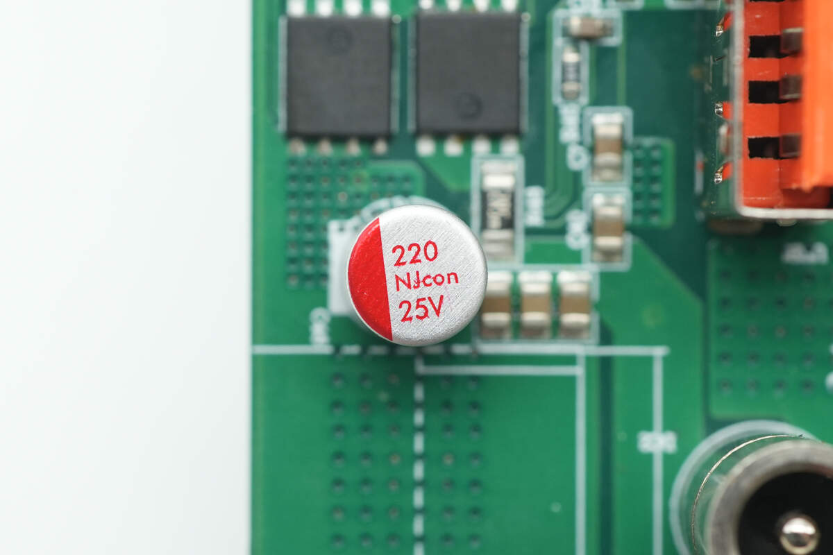
The solid capacitor used for the USB-C2 port is also from NJcon, with the same specification of 25V 220μF.
The VBUS MOSFETs for the USB-C2 port are also marked with ET6300.
The solid capacitor used for output filtering on the USB-A2 port is also from NJcon, with a specification of 25V 220μF.
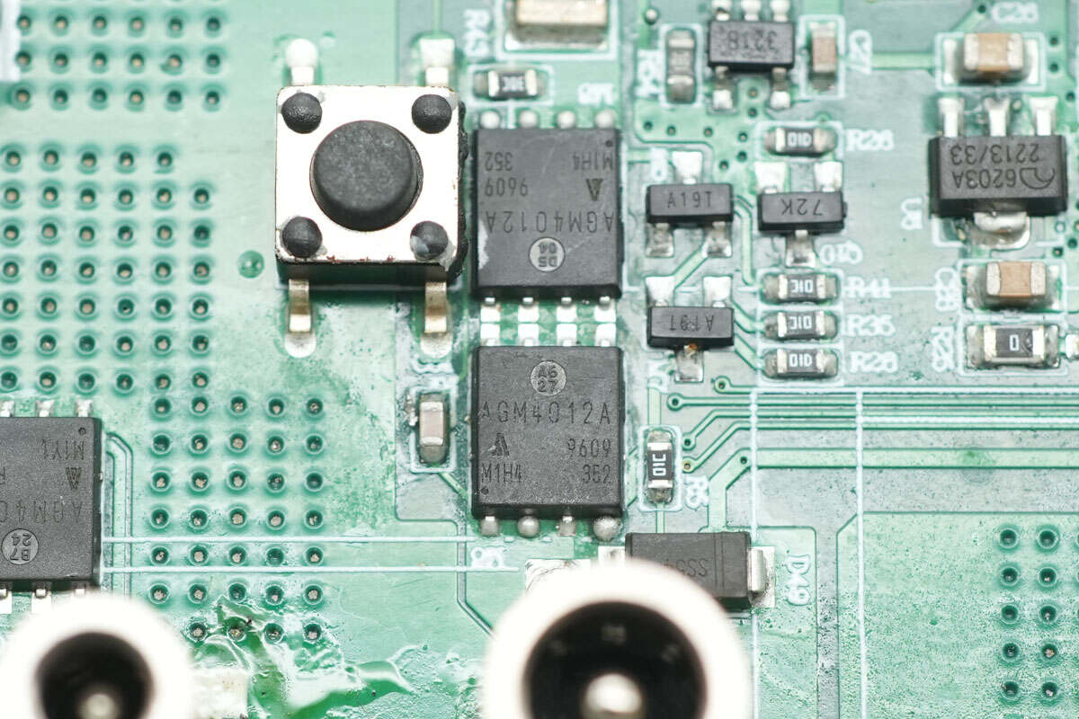
The MOSFET used for output control on the DC port is from AGMsemi, model AGM4012A. It has a voltage rating of 40V, an on-resistance of 1.1mΩ, and comes in a PDFN 5×6 package.
Close-up of the DC output port.
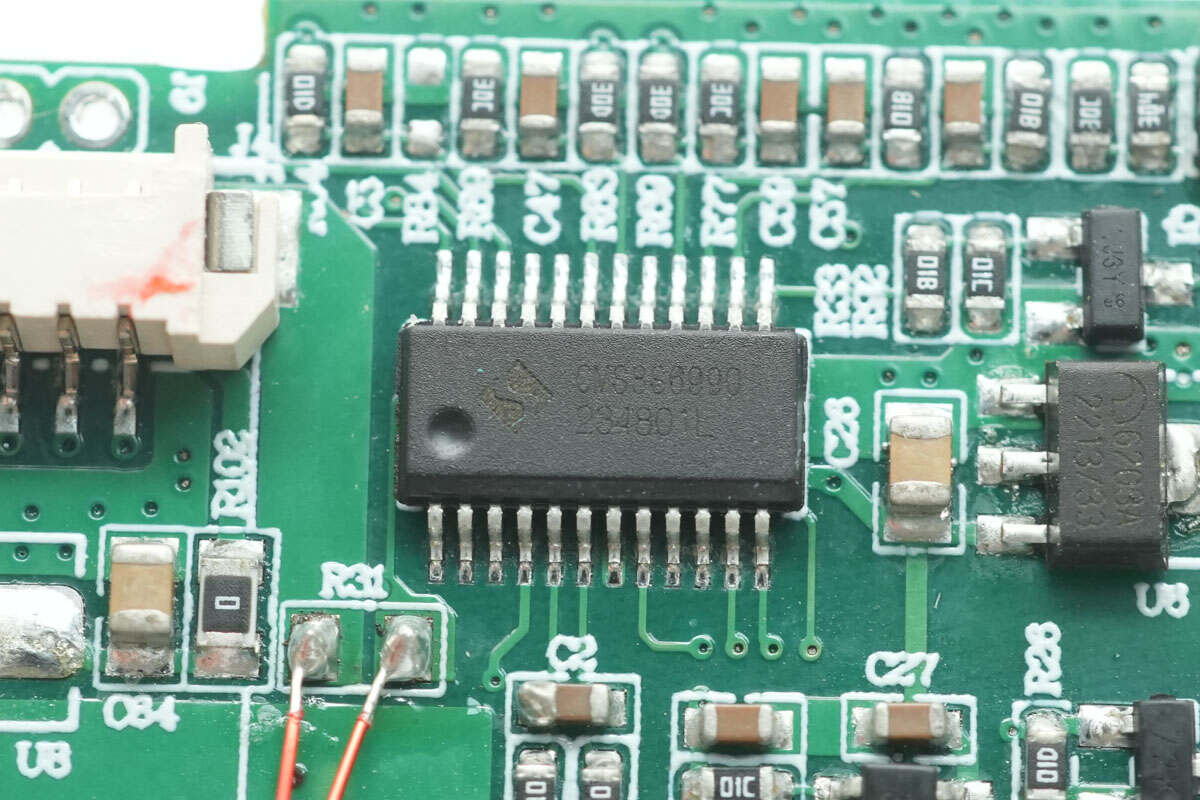
The MCU used for charging control is from Cmsemicon, model CMS8S6990. It is an enhanced 1T 8051 Flash MCU packaged in SSOP24.
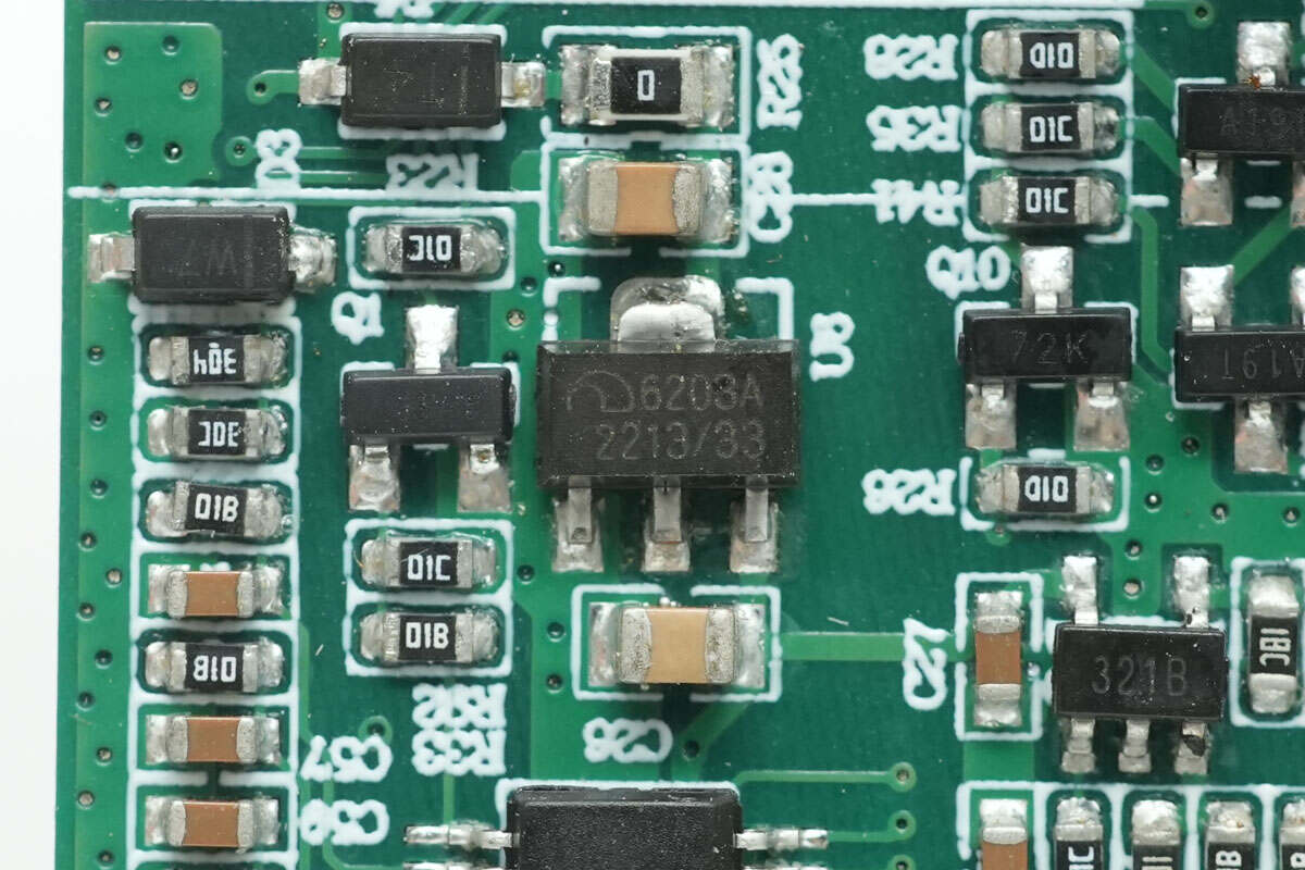
The voltage regulator chip used to power the MCU is from Microne, marked with 6203A.
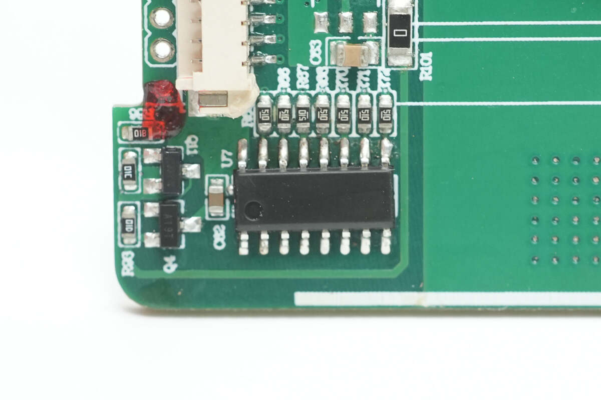
The microcontroller used to drive the LED digital display is unknown or unspecified.
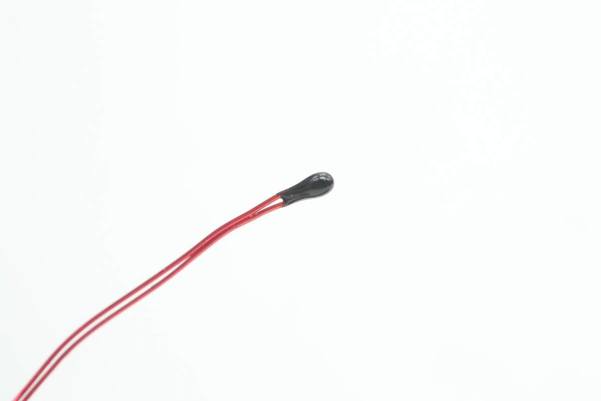
Close-up of the thermistor.
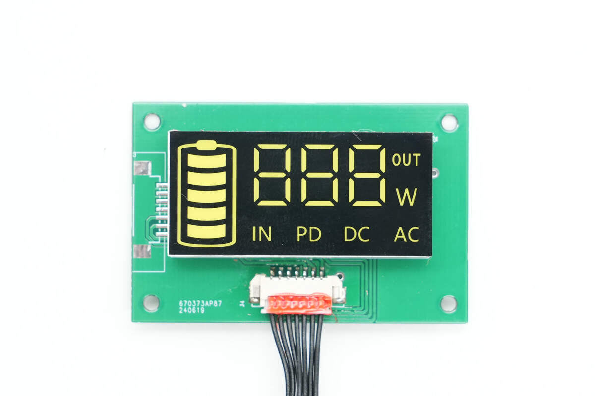
The digital display uses a separate PCB, with the connector socket reinforced by adhesive.
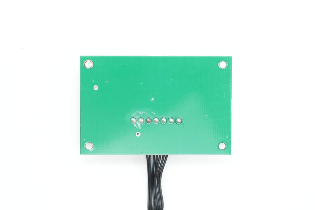
There are no components on the backside.
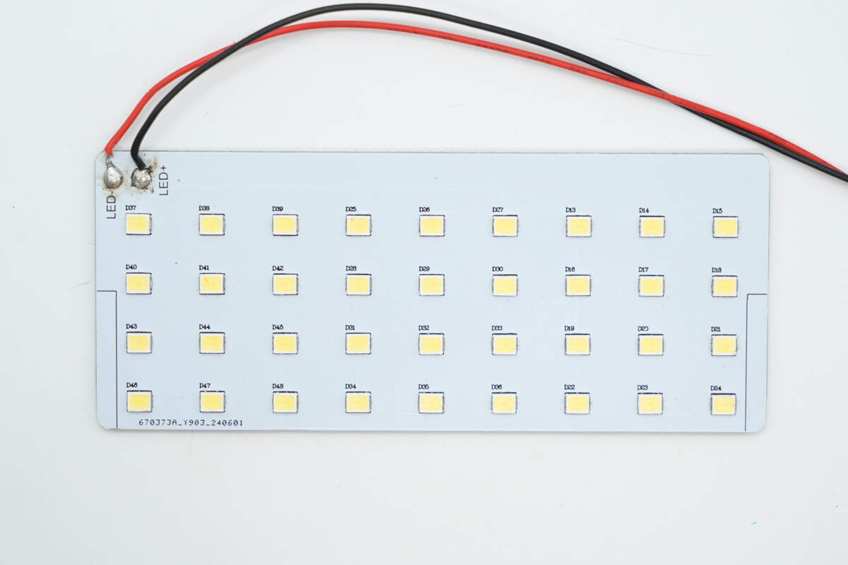
The LED light board has 36 LED beads arranged in a 9×4 matrix.
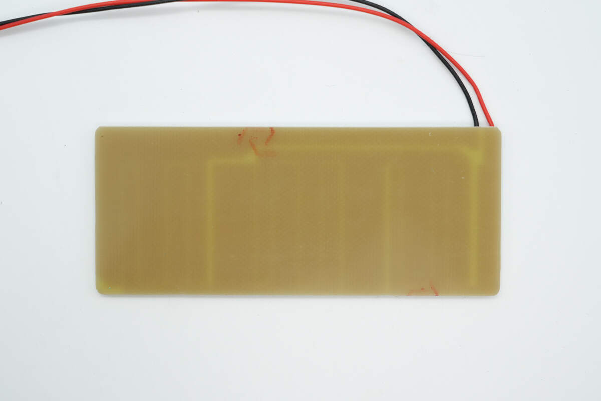
There are no components on the back side.
Well, those are all components of the Newsmy P72 100W 72000mAh Portable Power Station.
Summary of ChargerLAB
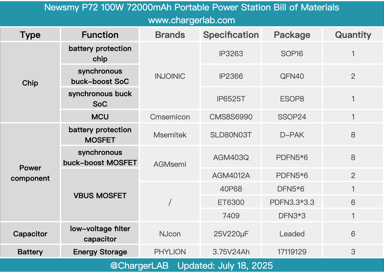
Here is the component list of the Newsmy P72 100W 72000mAh Portable Power Station for your convenience.
This power station is designed around three main selling points: compact size, large capacity, and ultra-fast charging. At the same time, it incorporates practical features such as a digital display, lighting, and solar charging to meet users’ needs for portability, endurance, and fast charging during outdoor activities.
It is equipped with two USB-A and two USB-C ports, supporting 18W QC output and 100W PD bi-directional fast charging, respectively. The input power of the two USB-C ports can be combined, providing up to 200W input power to quickly recharge the device. Coupled with the built-in 72,000mAh battery pack, it effectively eliminates any worries about running out of power.
After taking it apart, we found that the interior consists of four main modules: the master control PCB, LED light board, LED digital display, and battery pack. All modules use plug-in connectors, facilitating easy assembly and production. The battery pack uses PHYLION lithium iron manganese phosphate cells, which employ advanced automotive-grade materials and laminated cell technology. It supports over 3,000 charge-discharge cycles, offers high and low-temperature resistance, and provides enhanced safety and stability.
The battery pack is paired with the Injoinic IP3263 protection solution, along with a balancing circuit and thermistor for temperature monitoring. It supports 10 layers of safety protection, including overcurrent, overload, and low-temperature safeguards, providing comprehensive power security. The four USB ports’ charge and discharge management are handled by highly integrated SoC solutions, Injoinic IP2366 and IP6525T, with filtering performed by NJcon solid capacitors.
Related Articles:
1. Teardown of HONOR 100W USB-C GaN Charger
2. Teardown of AOHi The Youth PD 65W GaN 3-Port Charger (AOC-C019)
3. Teardown of UGREEN 67W 20000mAh Power Bank (PB550)