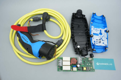
Introduction
MENNEKES is a German manufacturer of high-quality industrial electrical equipment and a pioneer in Europe’s electric vehicle charging standards. By contributing its core technology—the Type 2 connector—and continuously developing forward-looking smart charging solutions, the company has established itself as a global leader in electric mobility.
We obtained an 8A EV charging cable from MENNEKES. This unit features a split design, with the plug, in-cable control box (ICCB), and charging connector constructed as separate components. The total cable length is approximately 4.5 meters, and it uses a yellow cable. Both the control box and the charging connector are made from a combination of blue plastic and black plastic/rubber materials.
The charger supports an 8A charging current and is equipped with a 10A plug. The control box includes indicator lights to display charging status. The charging connector is fitted with a protective dust cap, which helps prevent contamination and oxidation, thereby ensuring reliable charging performance. A detailed teardown of this product is presented below to examine its internal design and material selection.
Product Appearance

This charging cable features a yellow cord, with a control box and connector designed in a blue-and-black color scheme. It is supplied with an instruction manual.
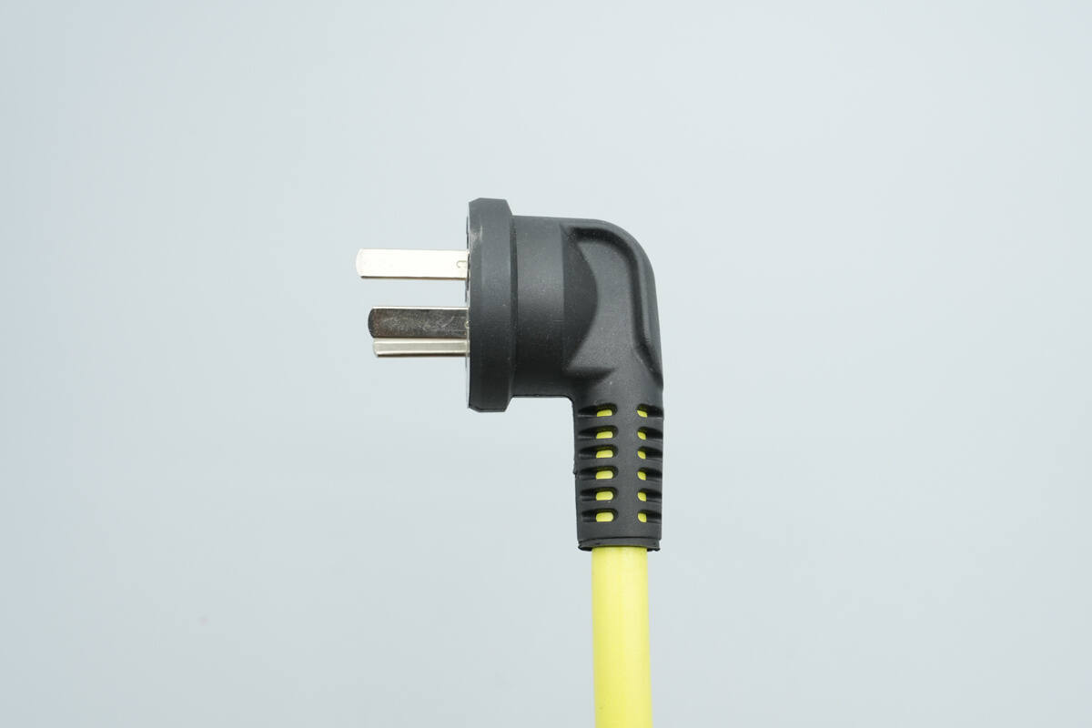
The input plug is a three-pin type.
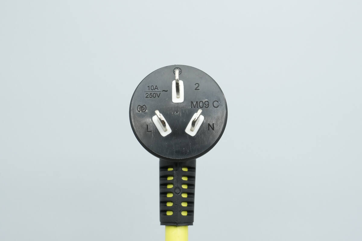
The plug is rated at 10A, 250V~.
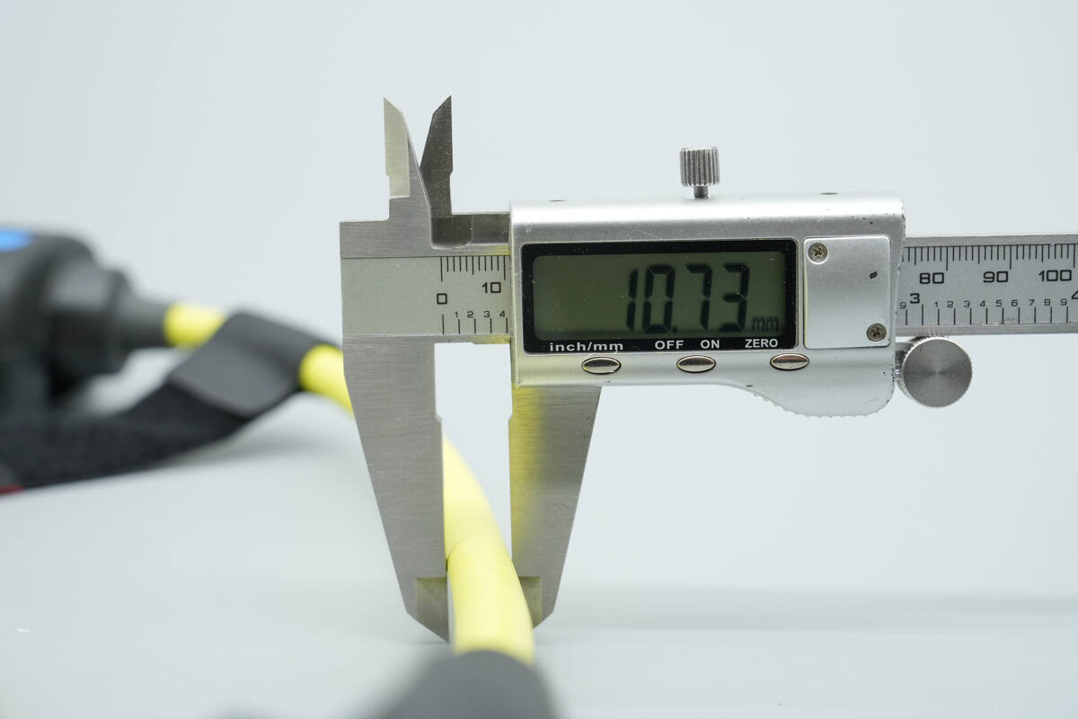
The diameter is about 10.7 mm (0.42 inches).
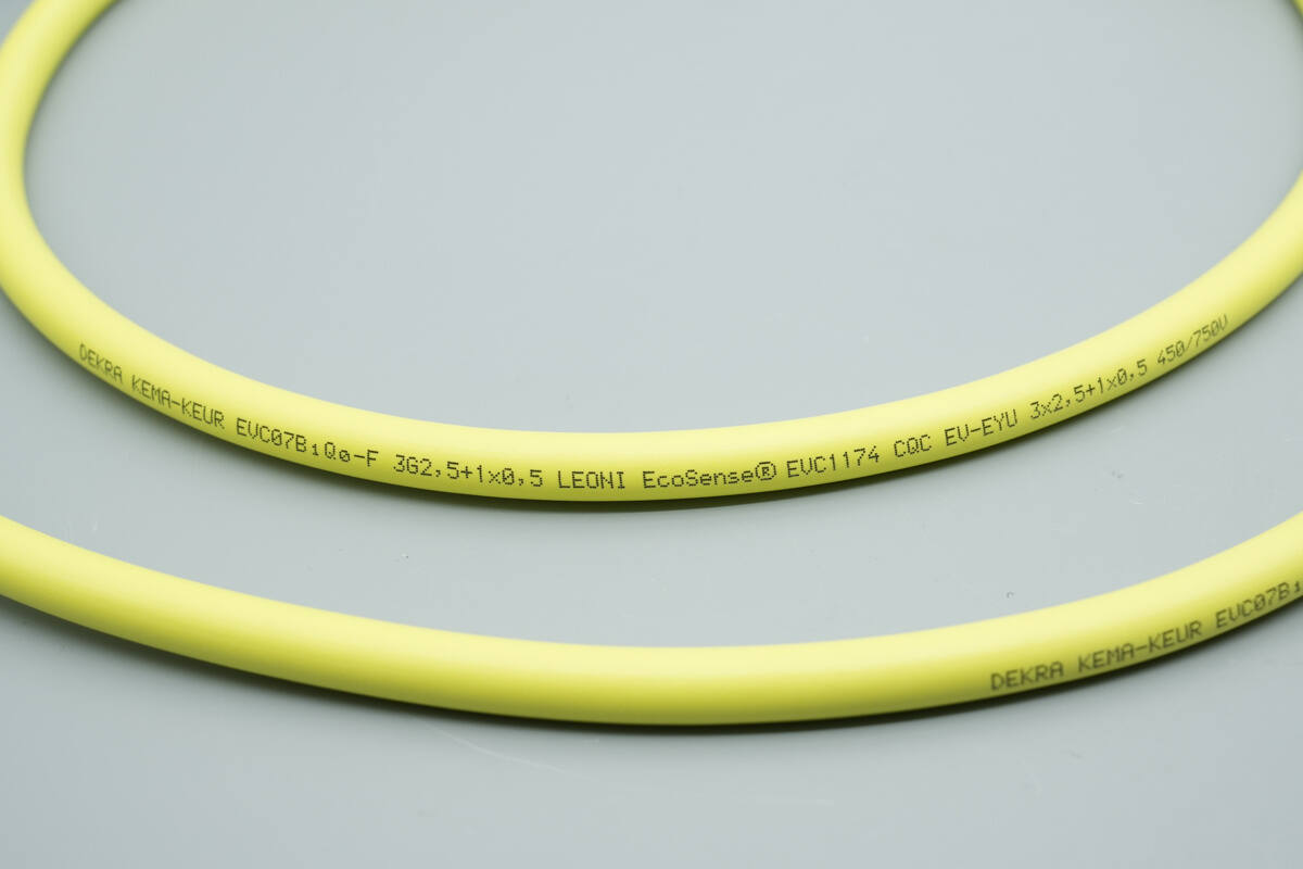
The cable specification is 3 × 2.5 mm² + 1 × 0.5 mm².
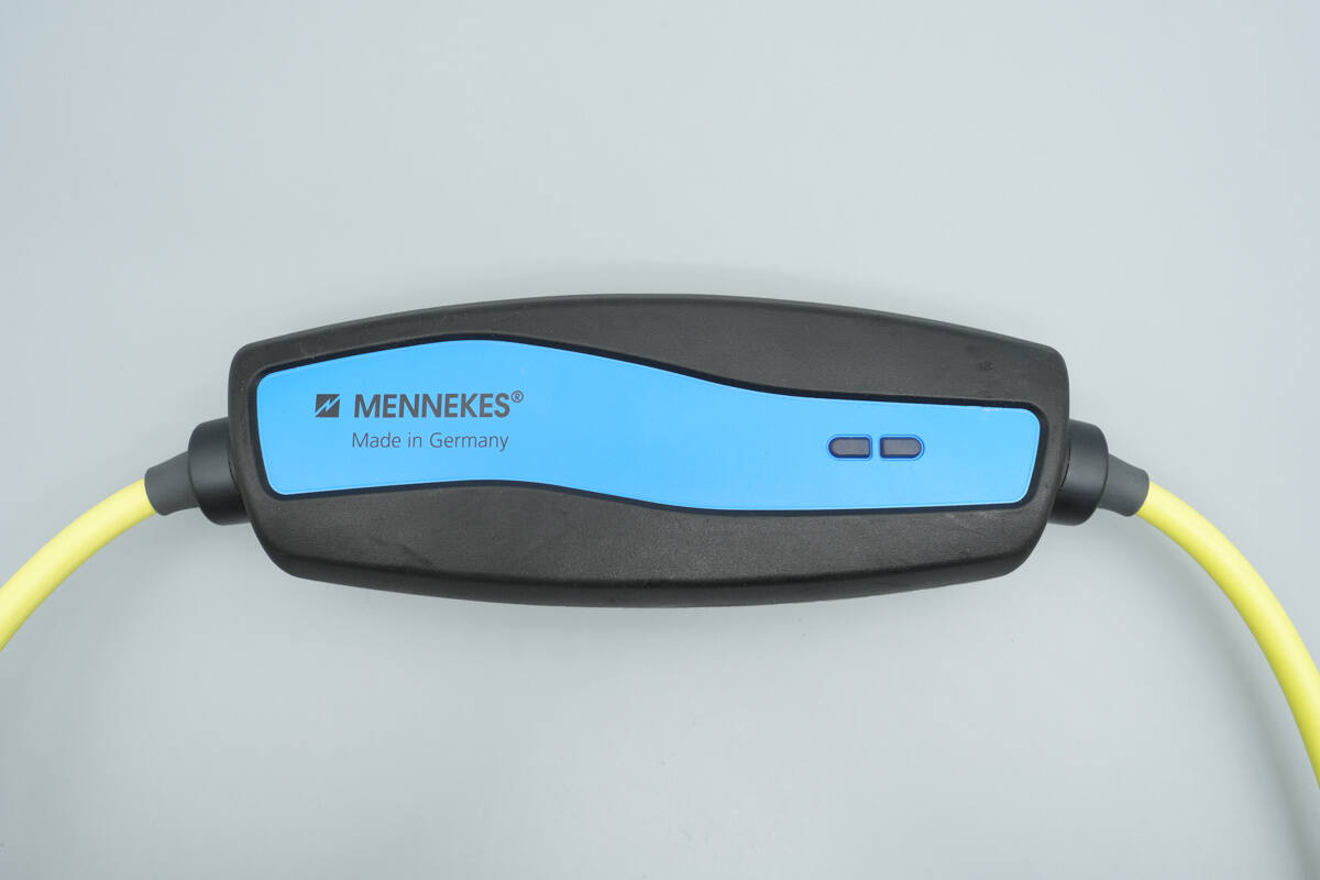
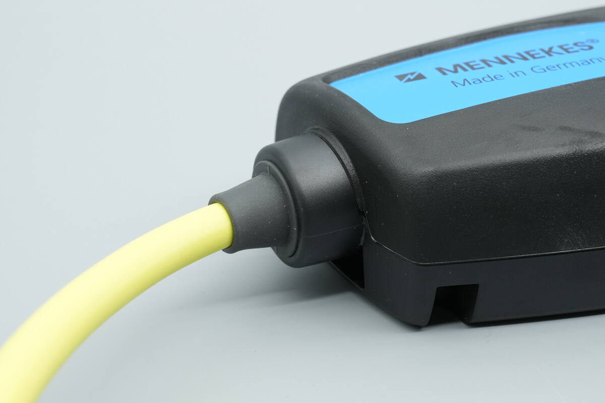
The charging cable control box has “MENNEKES” and “Made in Germany” printed on the left side, while indicator lights are located on the right side.
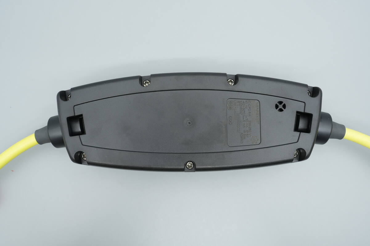
The back of the control box is secured with screws.
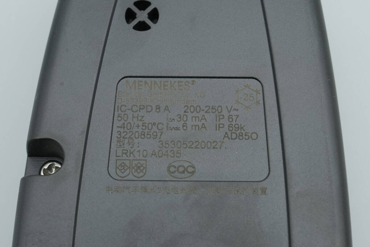
Close-up of the back of the control box:
IC-CPD8A200-250V~50Hz
IΔn 30mA IP67 -40/+50℃
IΔn dc 6mA IP69K
Model: 35305220027
LRK10A0435
Cable protection and control device for electric vehicle Mode 2 charging
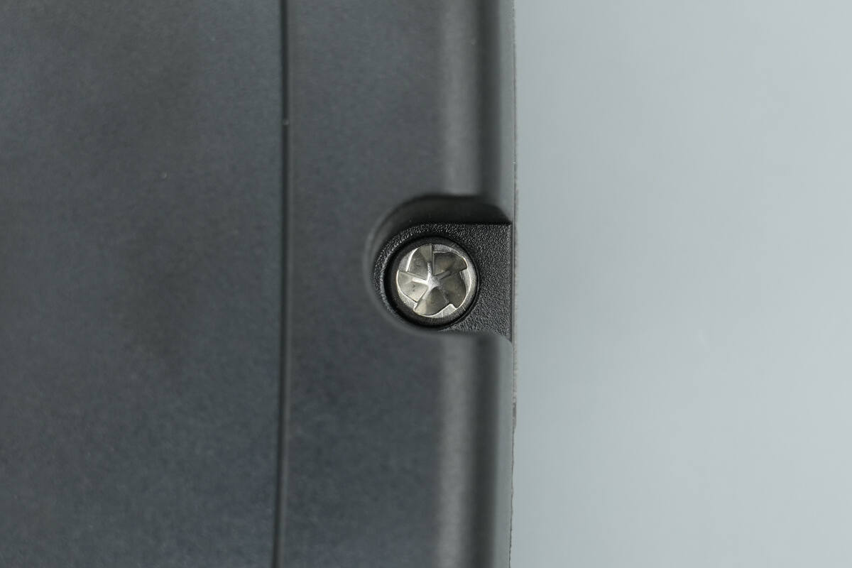
The control box is equipped with tamper-proof screws.
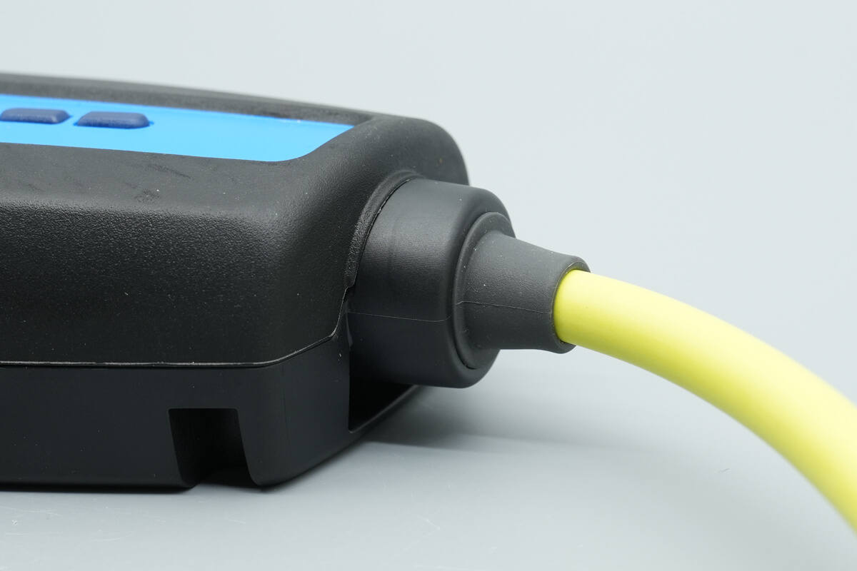
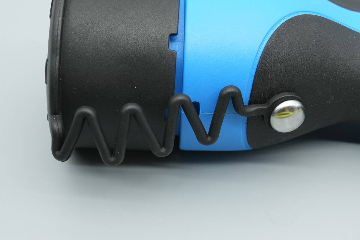
A protective sleeve is installed at the junction between the power cable and the charging control box to prevent bending.
A protective sleeve is also installed at the output end to prevent bending.
The length of the control box is about 230 mm (9.055 inches).
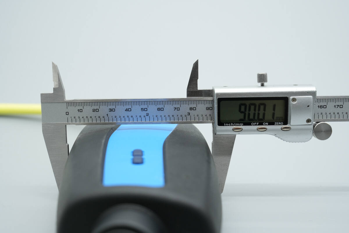
The width is about 90 mm (3.54 inches).
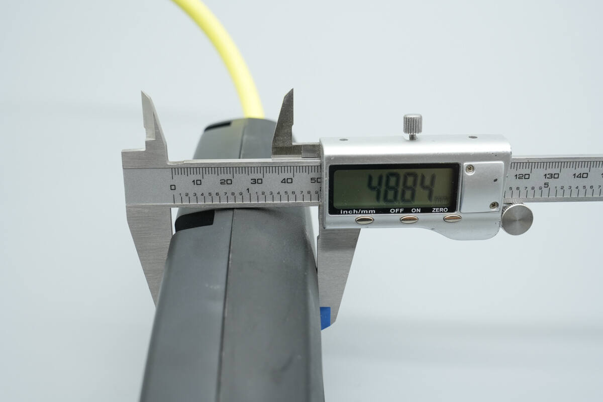
The thickness is about 48.8 mm (1.92 inches).
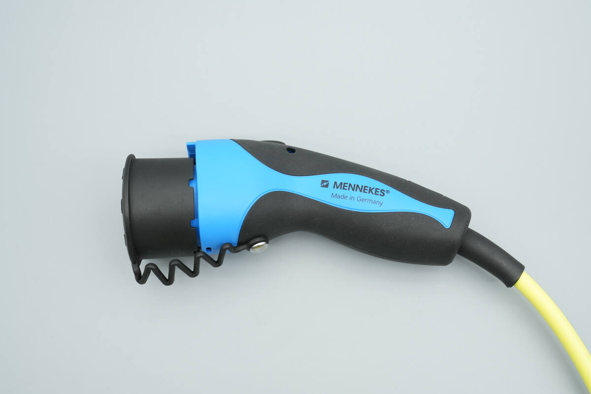
The side of the charging connector is marked with “MENNEKES” and “Made in Germany.”

The other side is also marked with MENNEKES and “Made in Germany.”
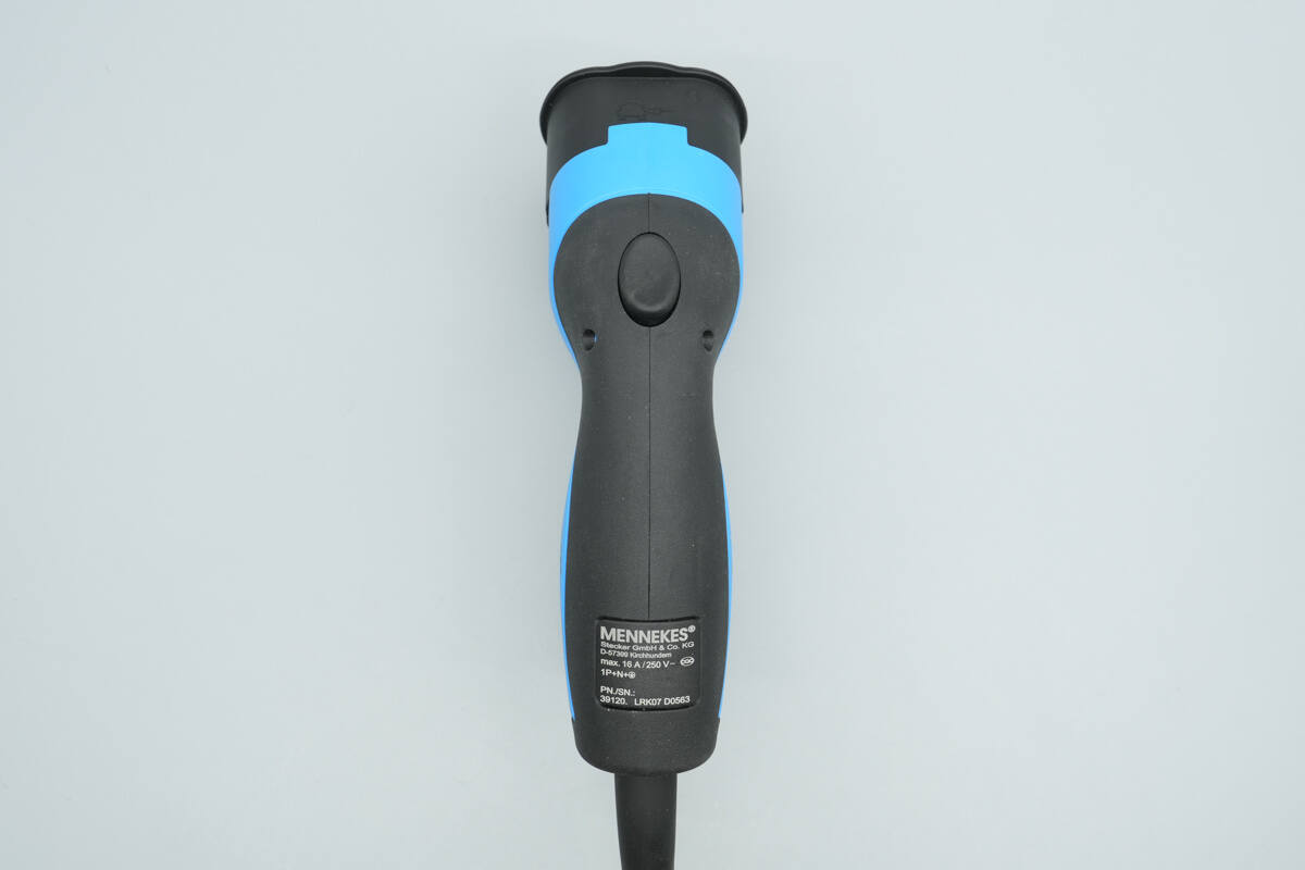
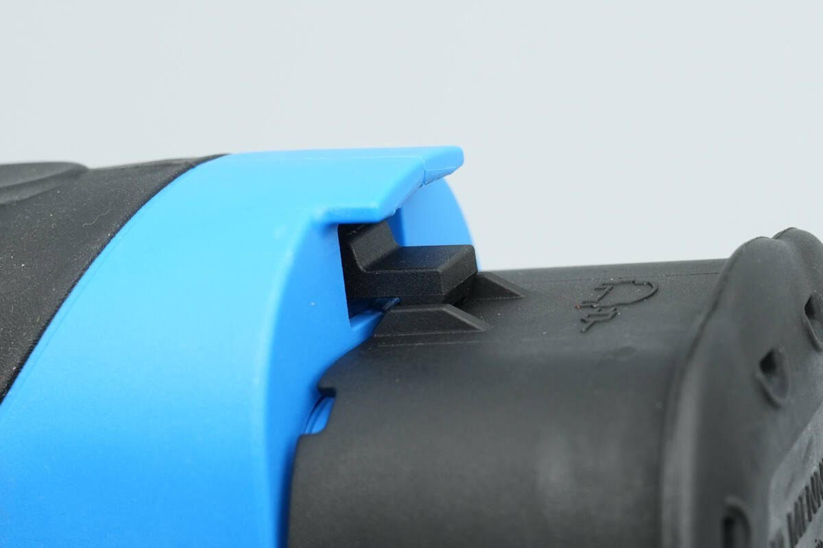
The body of the charging connector features a release button and an information label.
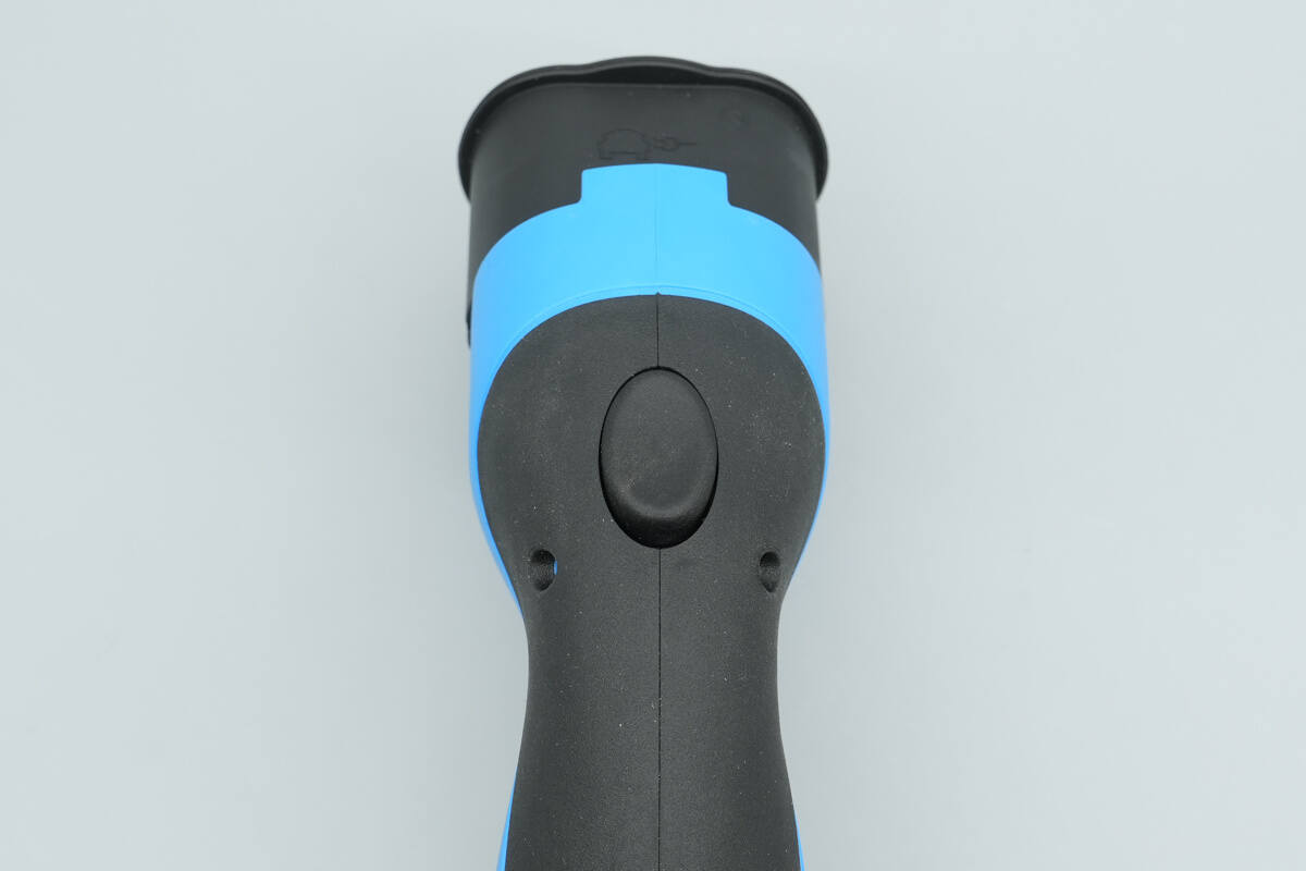
Close-up of the release button.
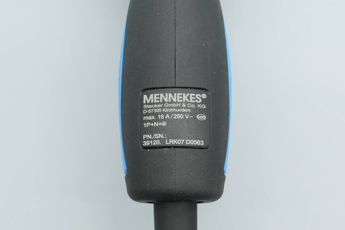
Supports 16A, 250V specifications.

The dust protection cap is marked with “MENNEKES” and “Made in Germany.”
The protective cap is equipped with an integrated tether.
Close-up of the locking clip.
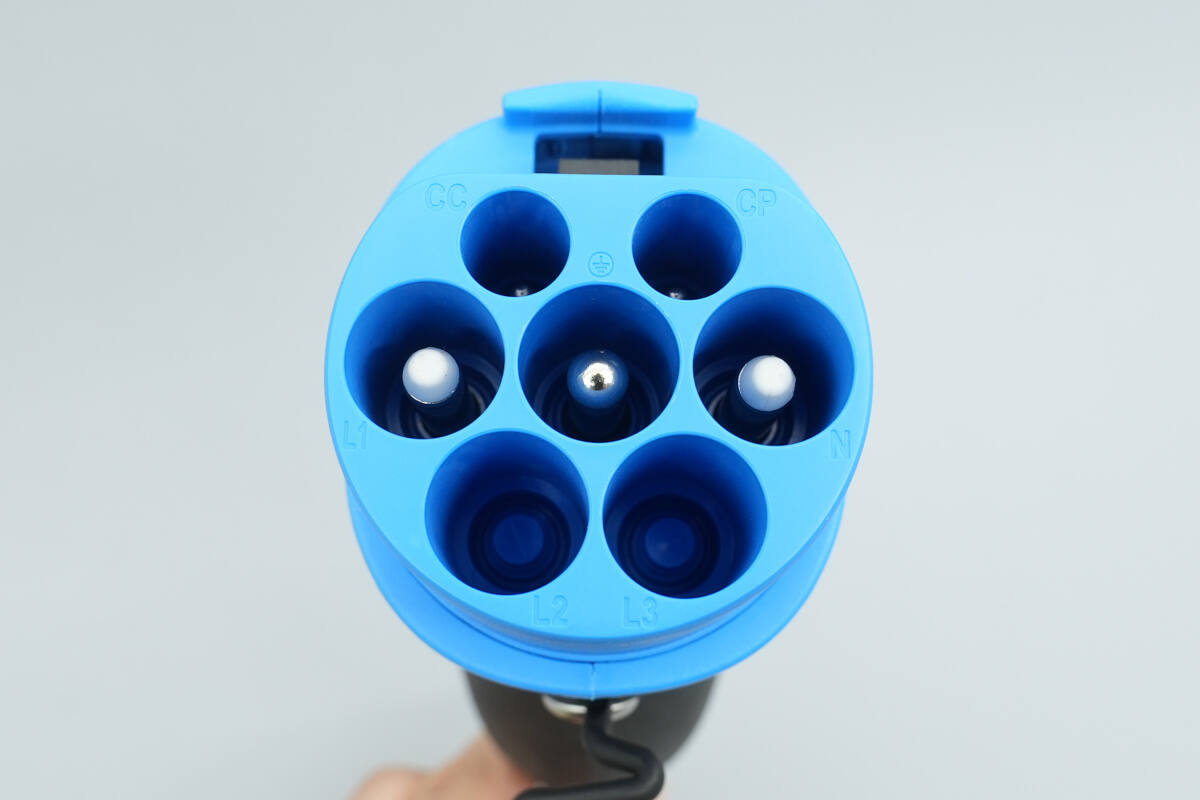
Close-up of the tip of the charging connector, compatible with a wide range of electric vehicle models from major brands.
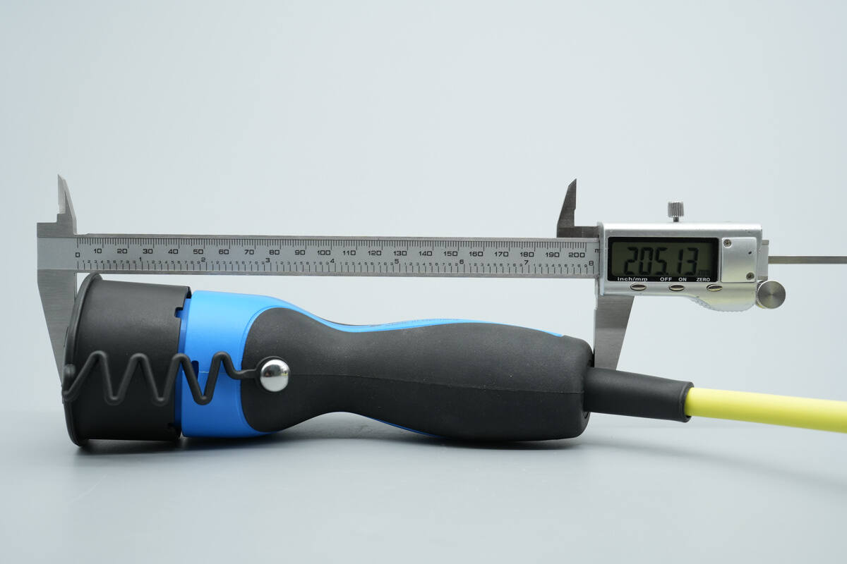
The length of the connector is about 205 mm (8.071 inches).
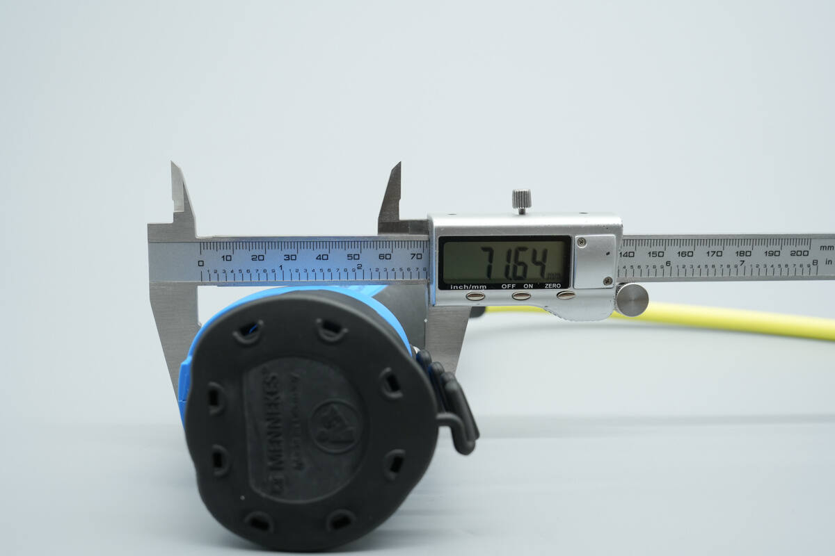
The width is about 71.6 mm (2.82 inches).
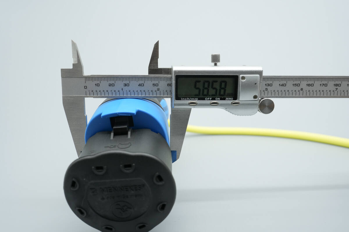
The thickness is about 58.6 mm (2.31 inches).
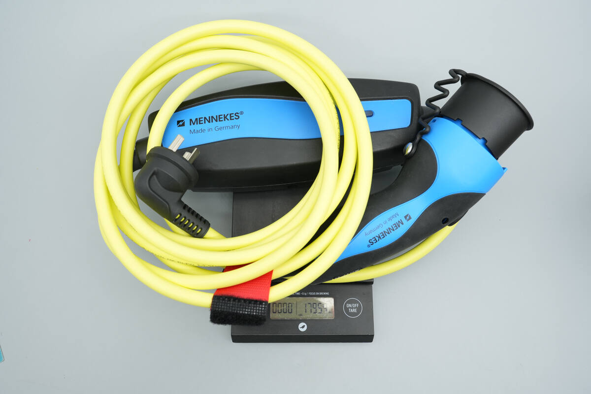
The weight is about 1795 g (63.32 oz).
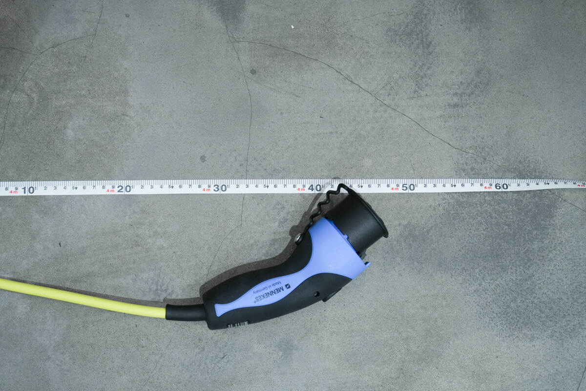
The total length is about 4.5 m (177.2 inches).
Teardown
Next, let's take it apart to see its internal components and structure.
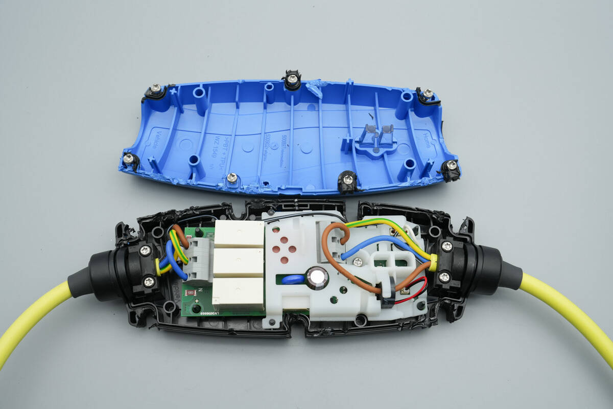
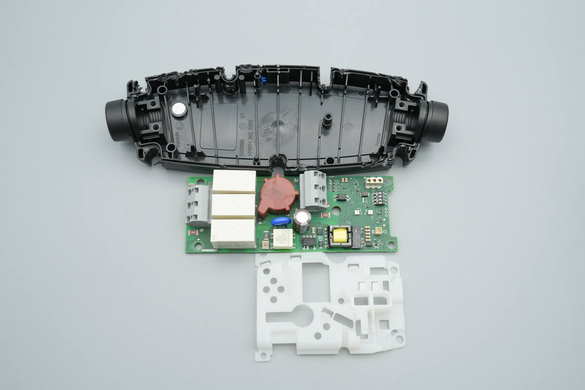
First, remove the control box casing to expose the PCBA module.
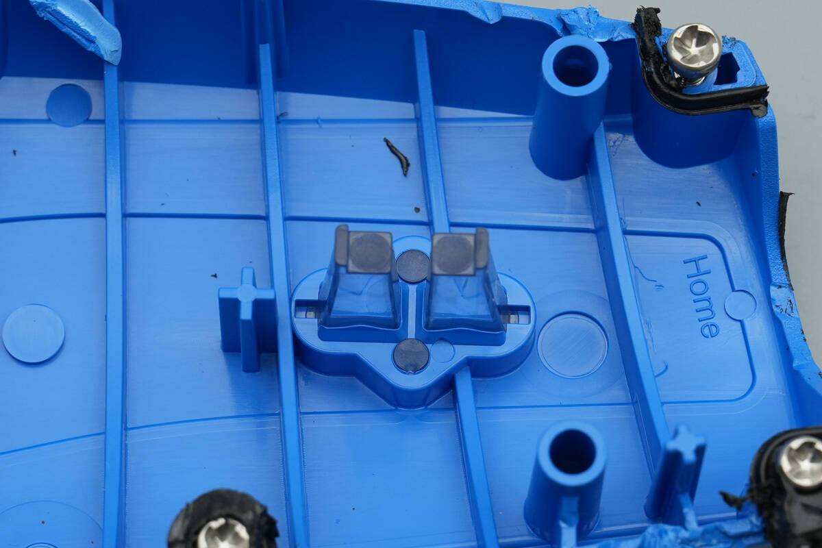
The interior of the casing is equipped with a light guide for the indicator LEDs.
The input and output wires are connected via connectors. The PCBA module is enclosed in plastic and secured with screws. A current transformer is also installed on the plastic enclosure.
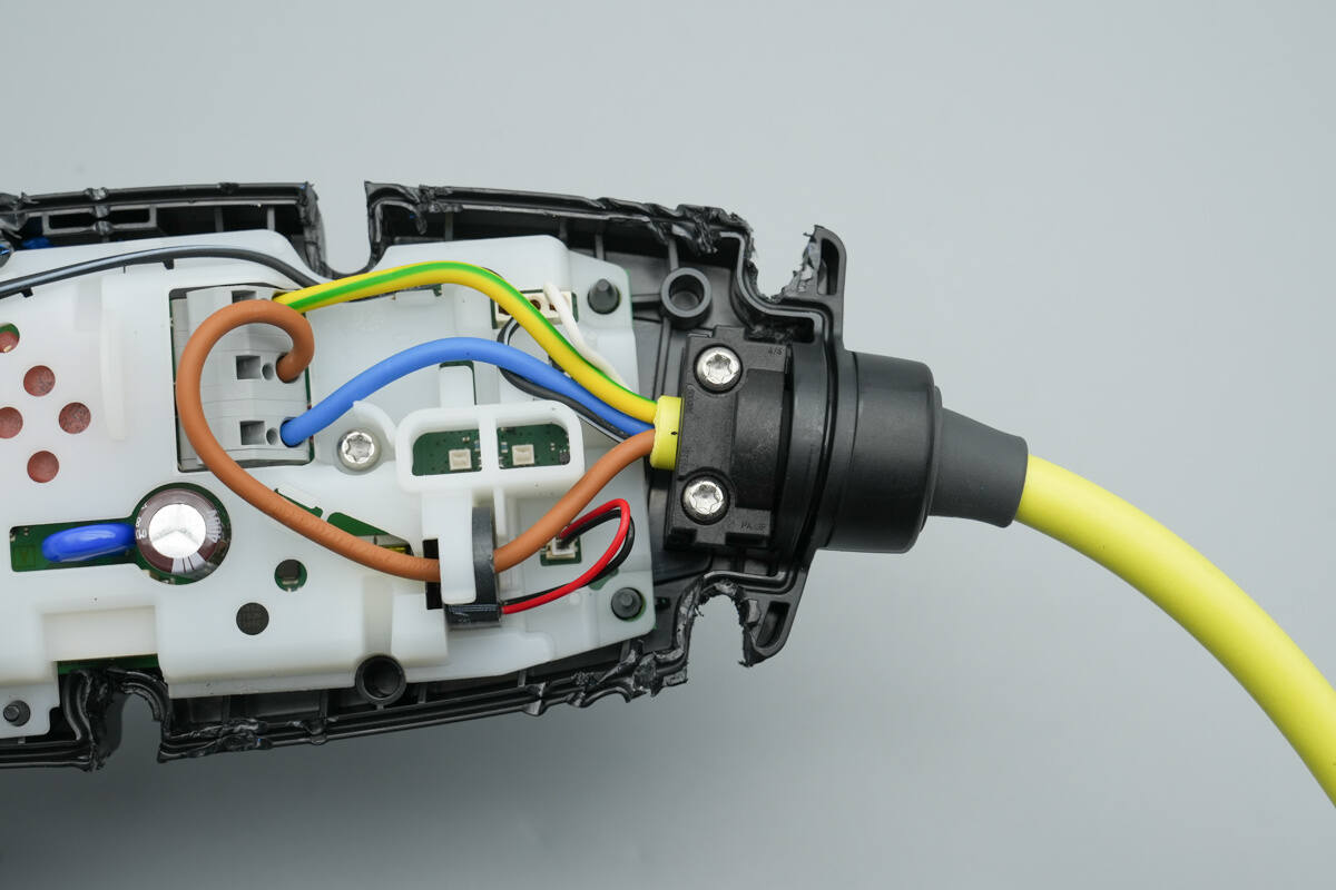
The injection-molded section of the input wire is secured to the casing with screws.
The injection-molded section of the output wire is also secured with screws.
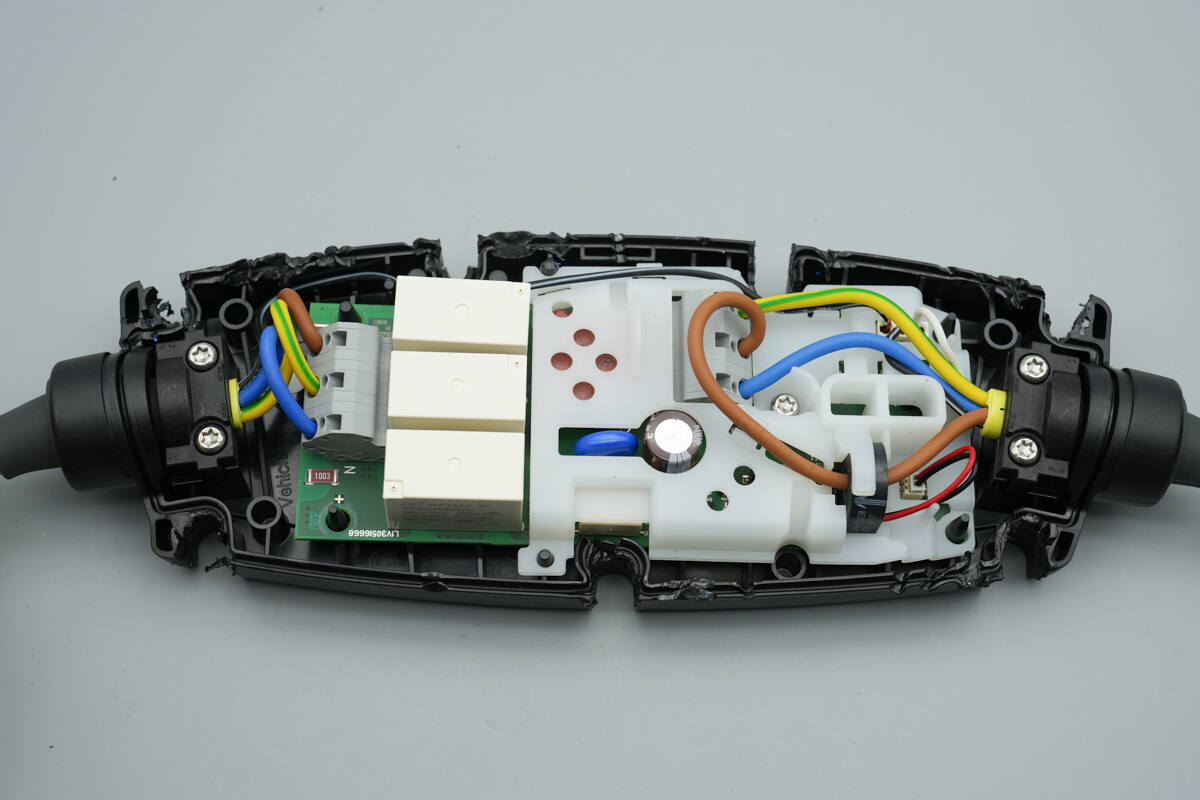
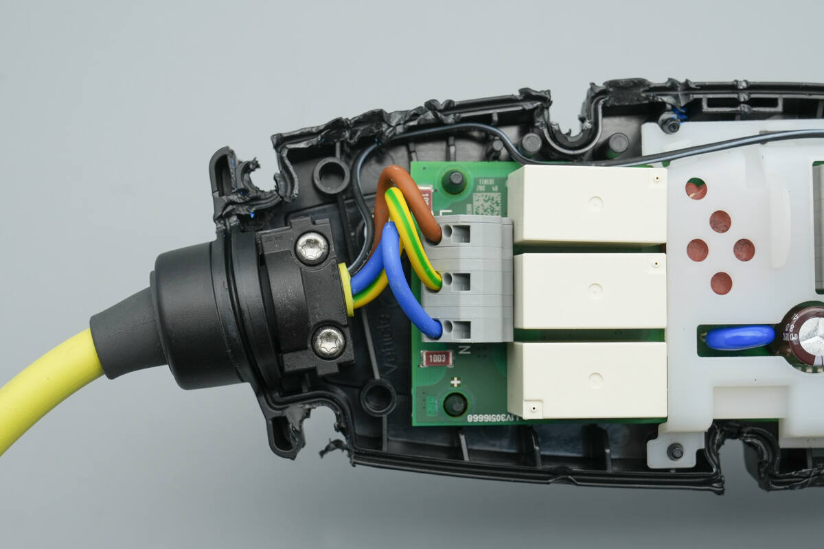
Unscrew the fastening screws and remove the PCBA module.
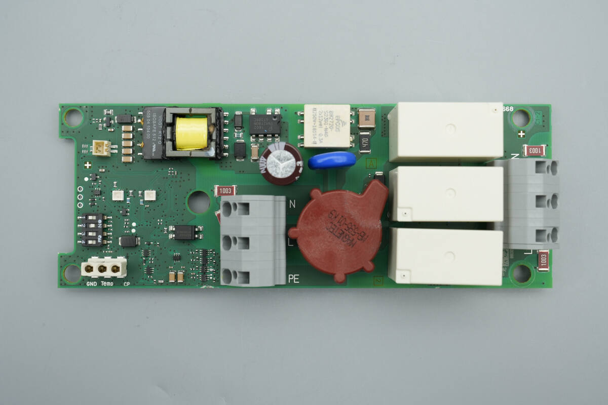
The front side of the PCBA features function configuration switches, connection sockets, a transformer, the main control chip, filter capacitors, an input connector, a varistor, a current transformer, a relay, and an output connector.
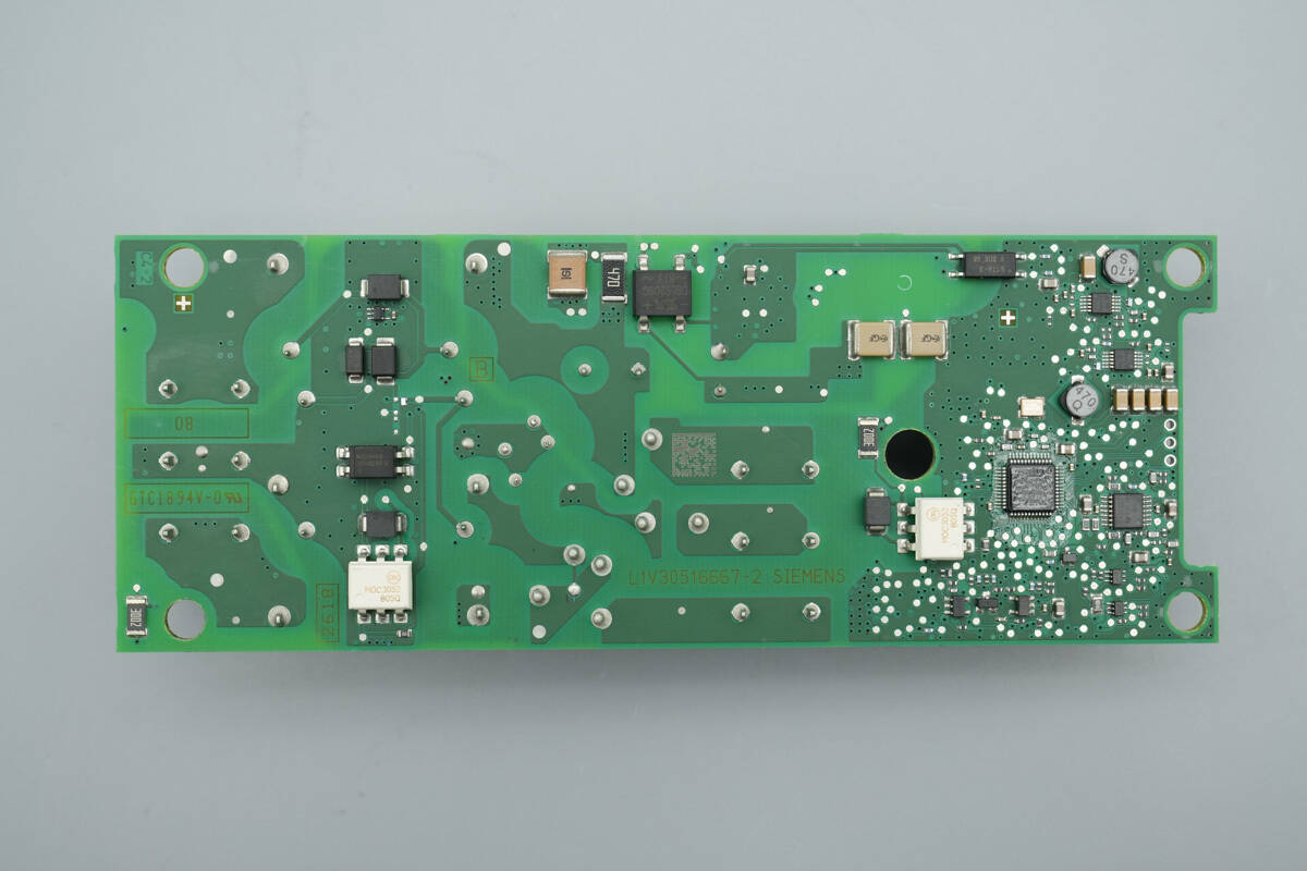
The back side is equipped with an isolation optocoupler, diodes, TVS, a bridge rectifier, SMD Y-capacitors, an MCU, an operational amplifier, and a buck converter chip.
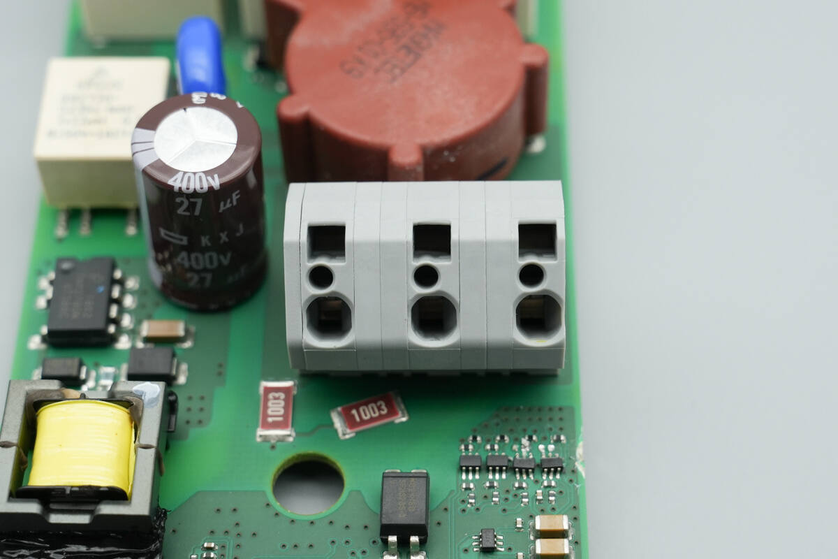
Close-up of the input terminal block.
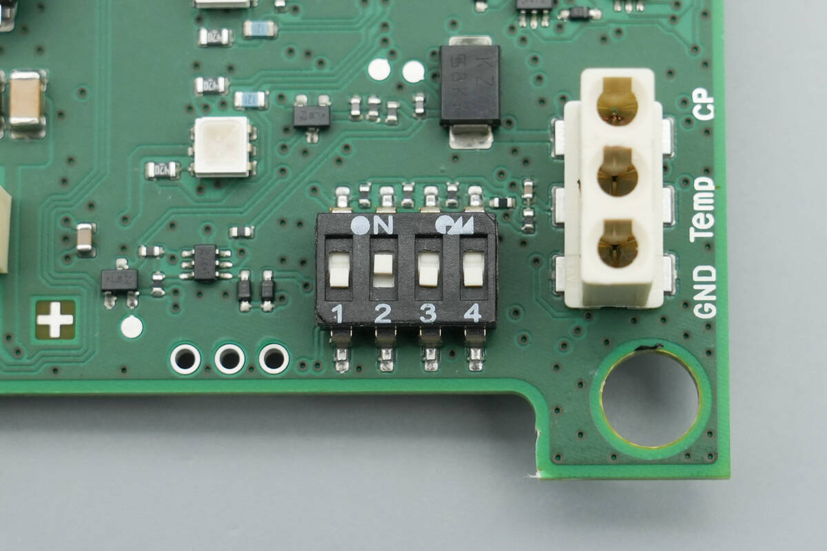
Close-up of the DIP switches and connection terminals used for function configuration.
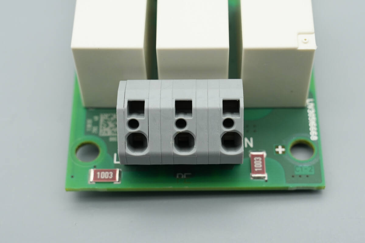
Close-up of the output terminal block.
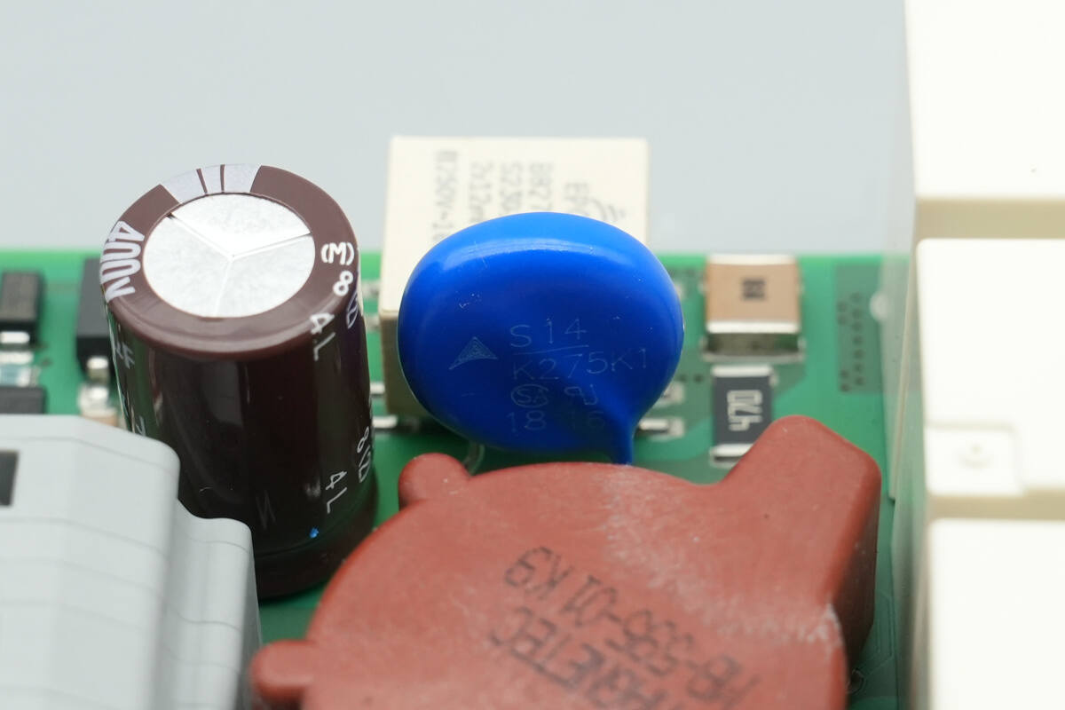
The input varistor is from TDK, part number S14K275K1, used to absorb overvoltage surges.
The safety X2 capacitor is from Holy Stone.
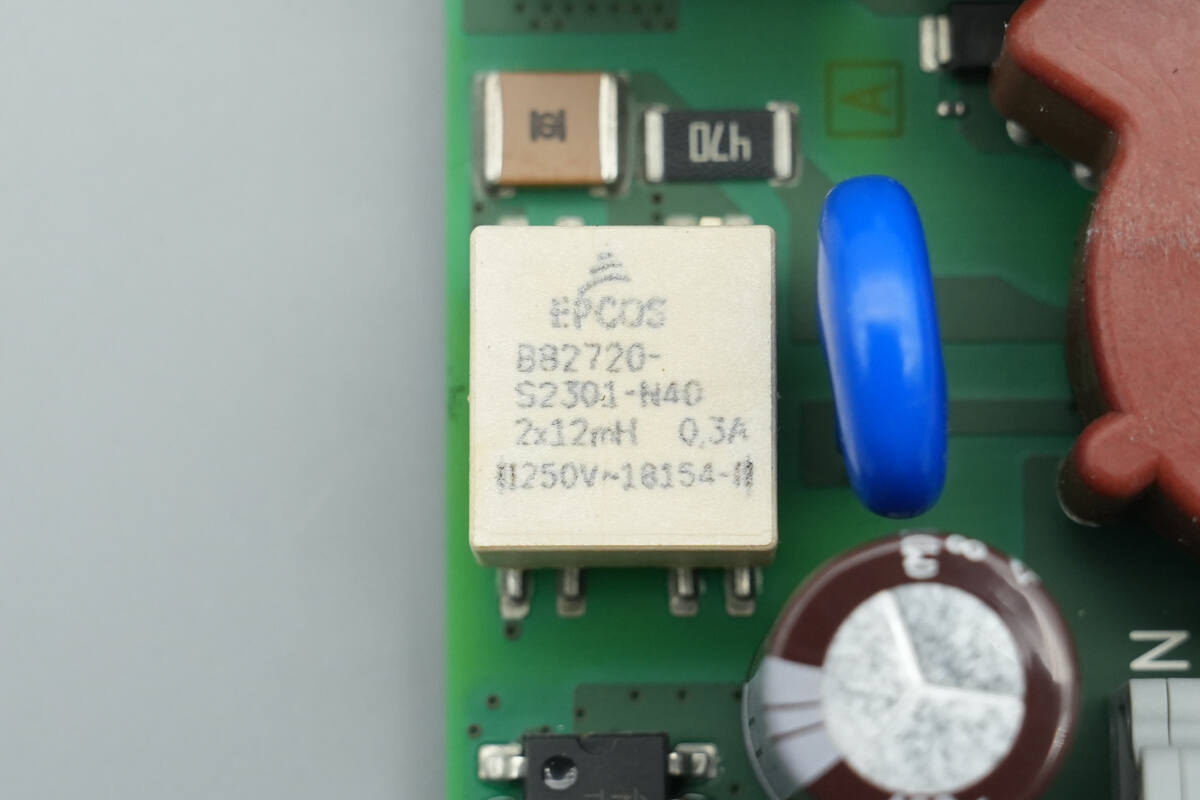
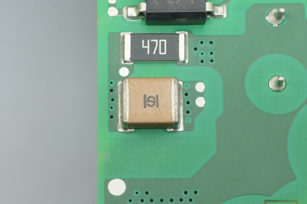
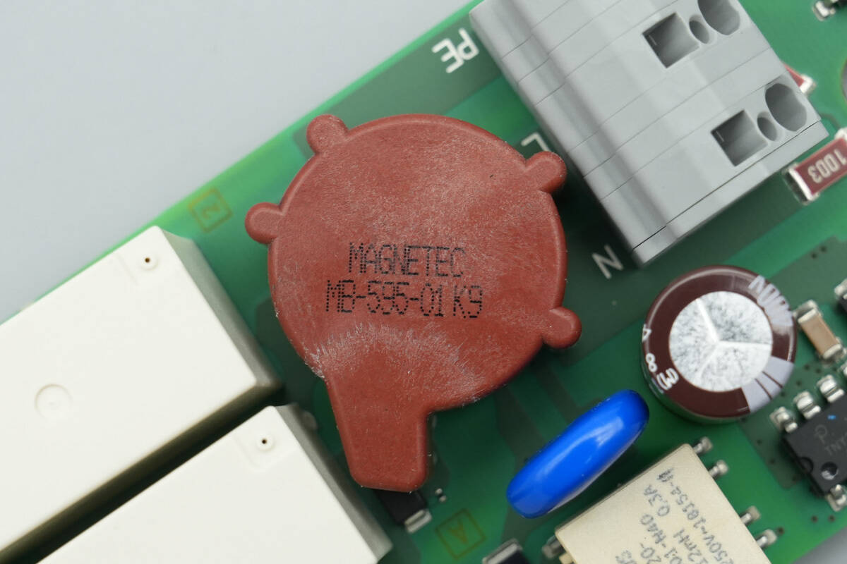
The common mode choke is from TDK and is surface-mounted.
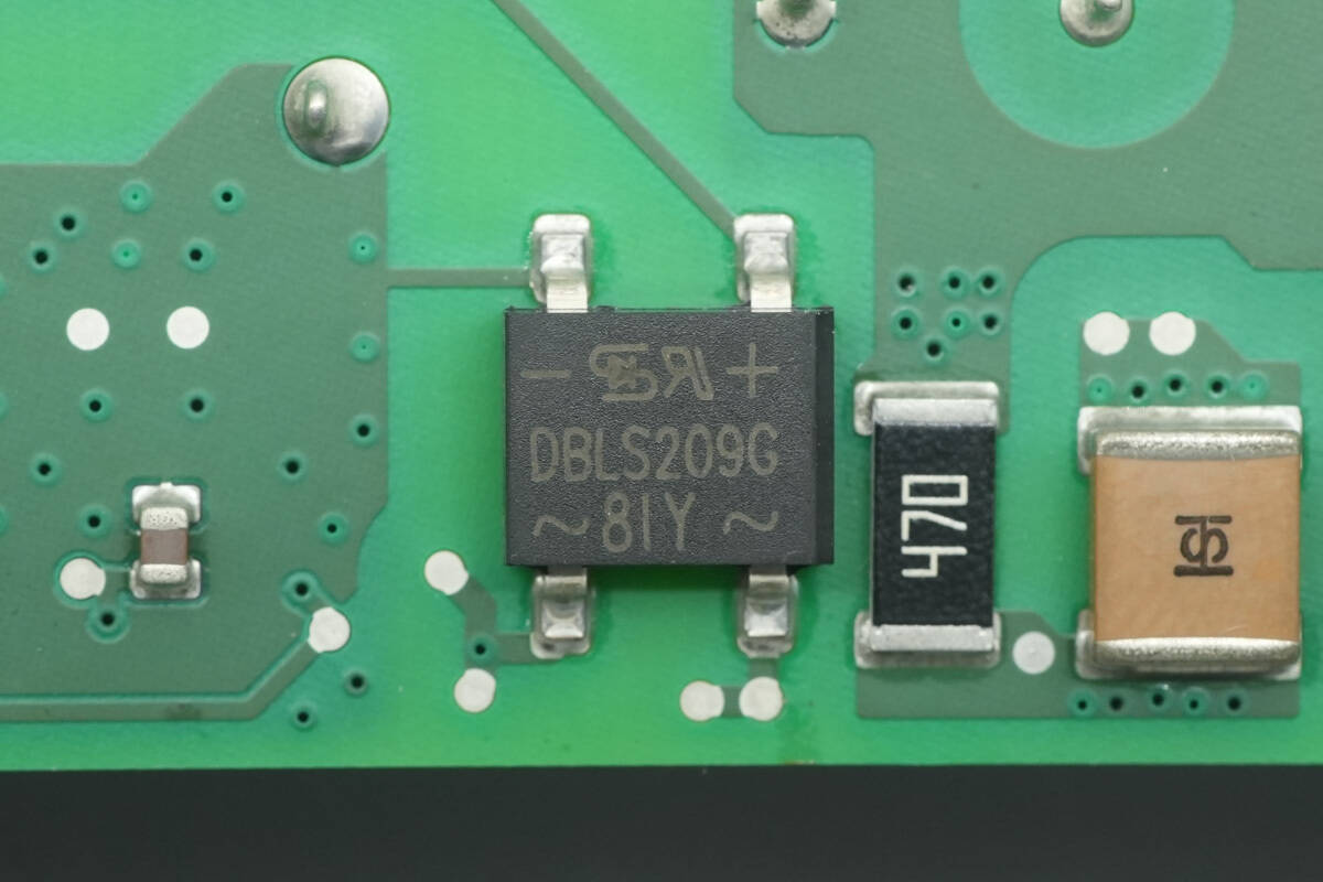
The bridge rectifier is from TSC, model DBLS209G, rated at 1400V 2A, and uses a DBLS package.
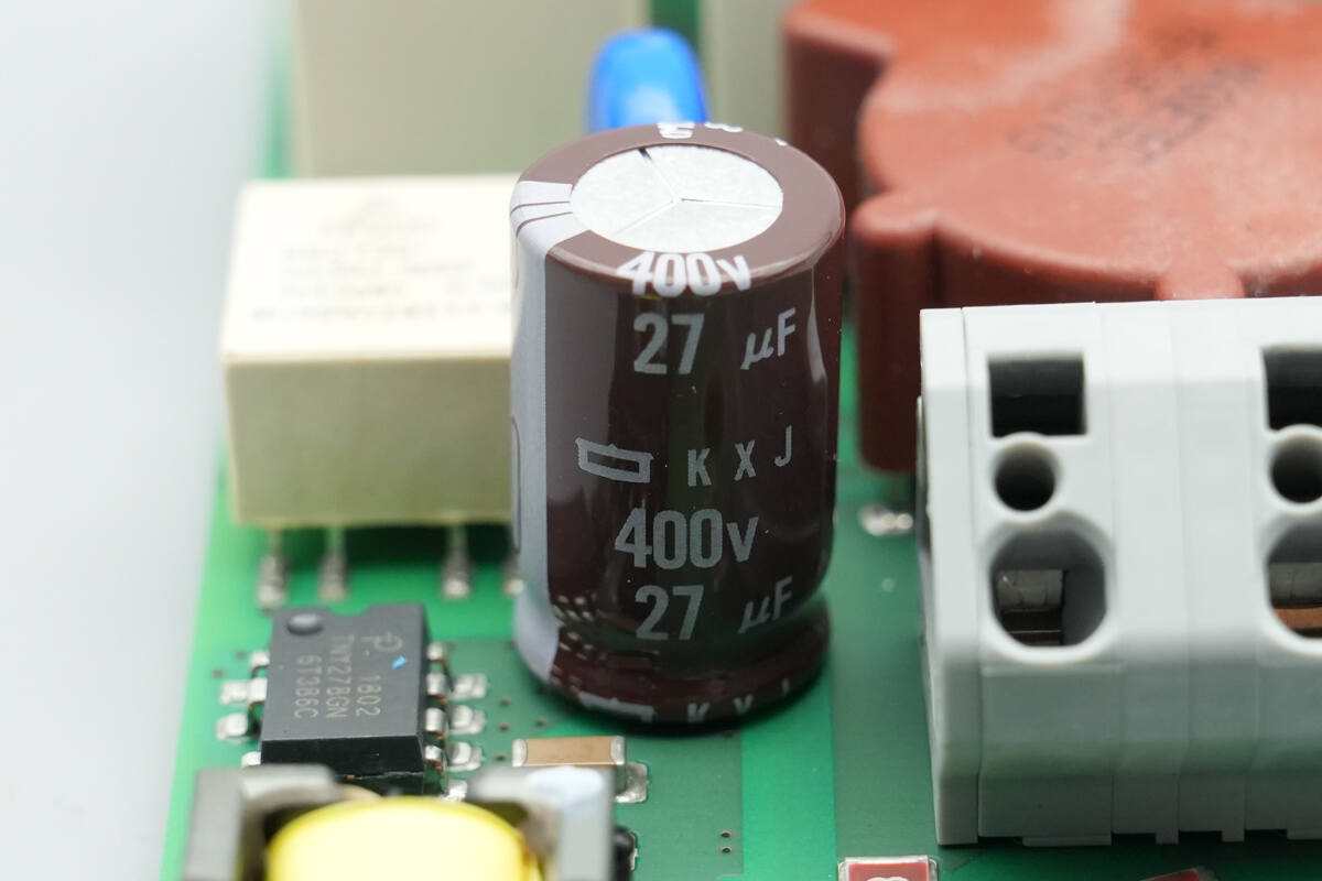
The high-voltage filter capacitor is from NCC, with a rating of 400 V, 27 μF.
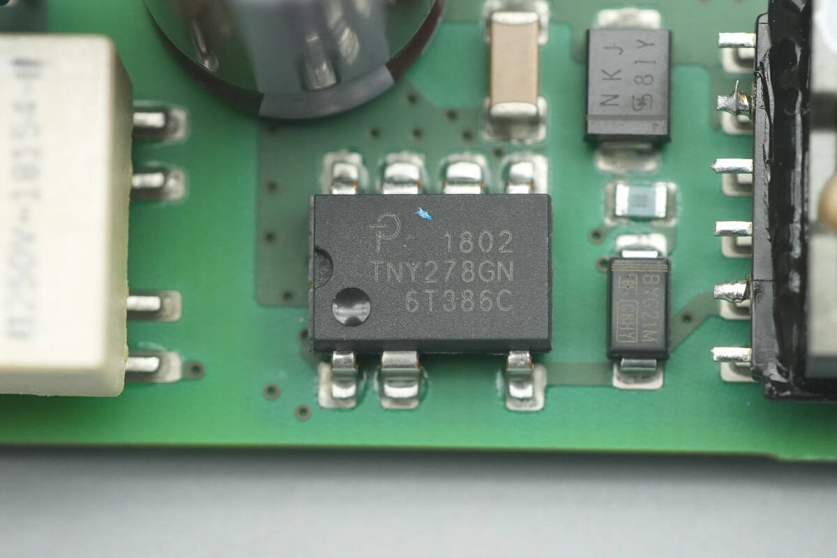
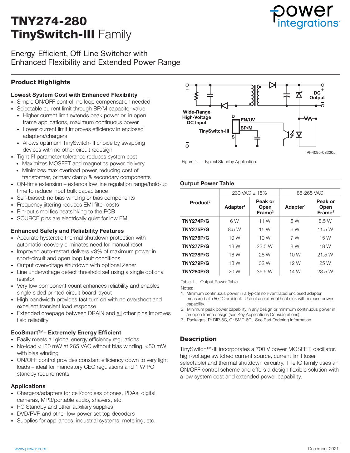
The switching power supply IC is from PI, model TNY278GN, part of the TinySwitch-3 series. It integrates a 700 V-rated MOSFET, supports 10 W output power under wide input voltage, and comes in an SMD-8C package.
Here is the information about PI TNY278GN.
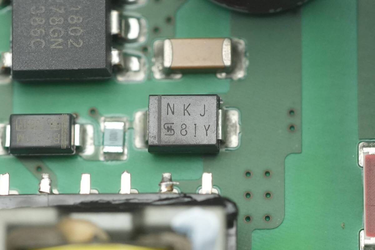
Diode marked with NKJ for snubber circuits.
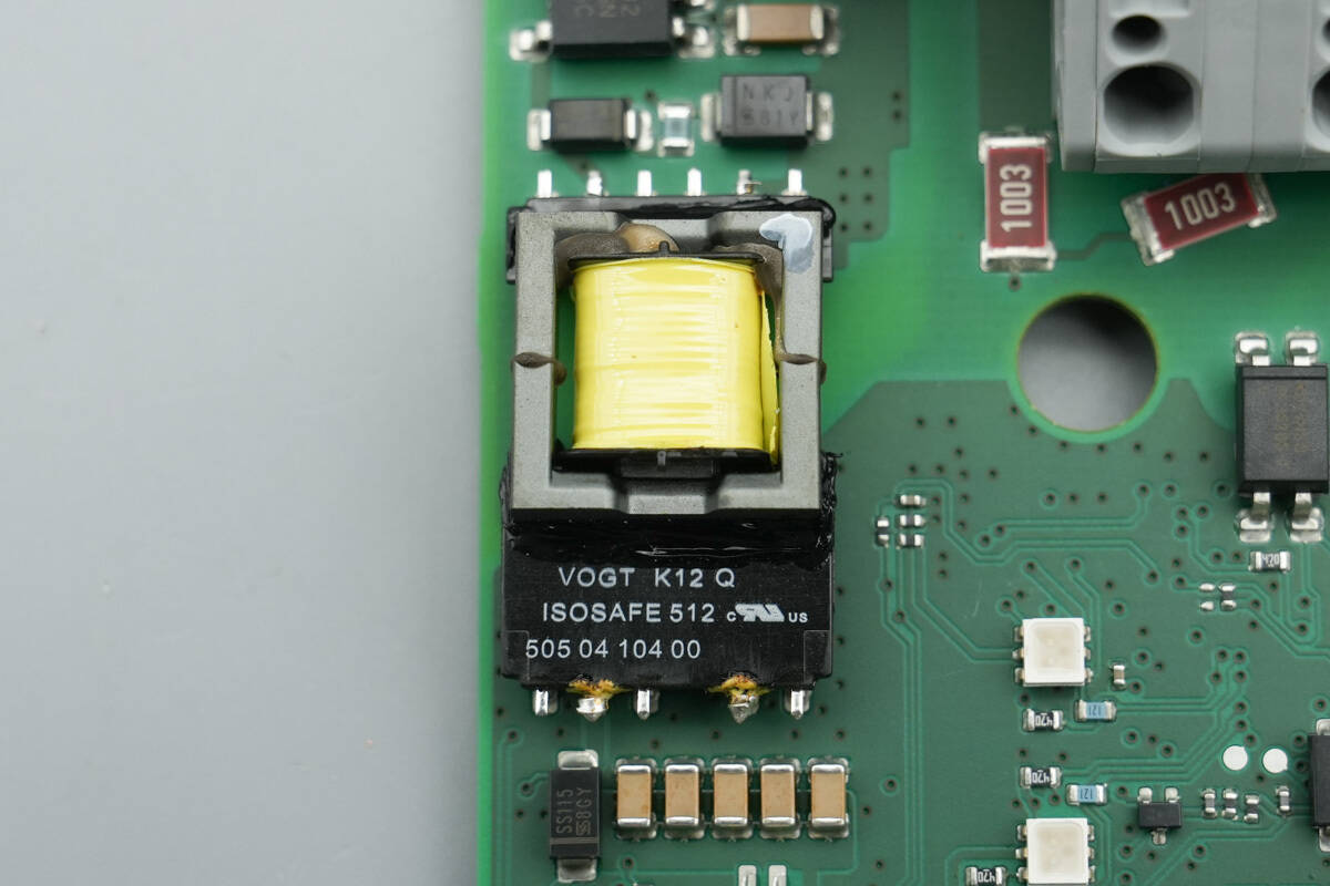
Close-up of the power transformer.
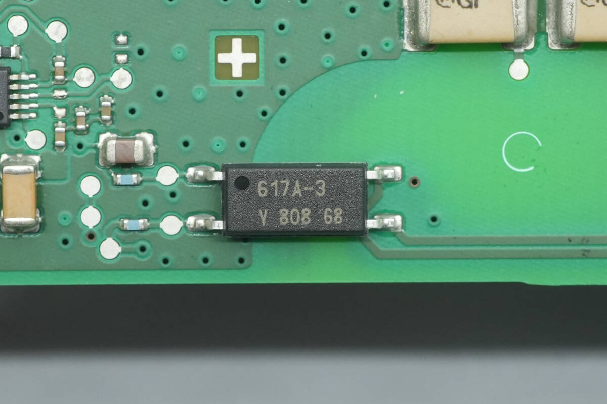
The optocoupler is from VISHAY, marked 617A-3.
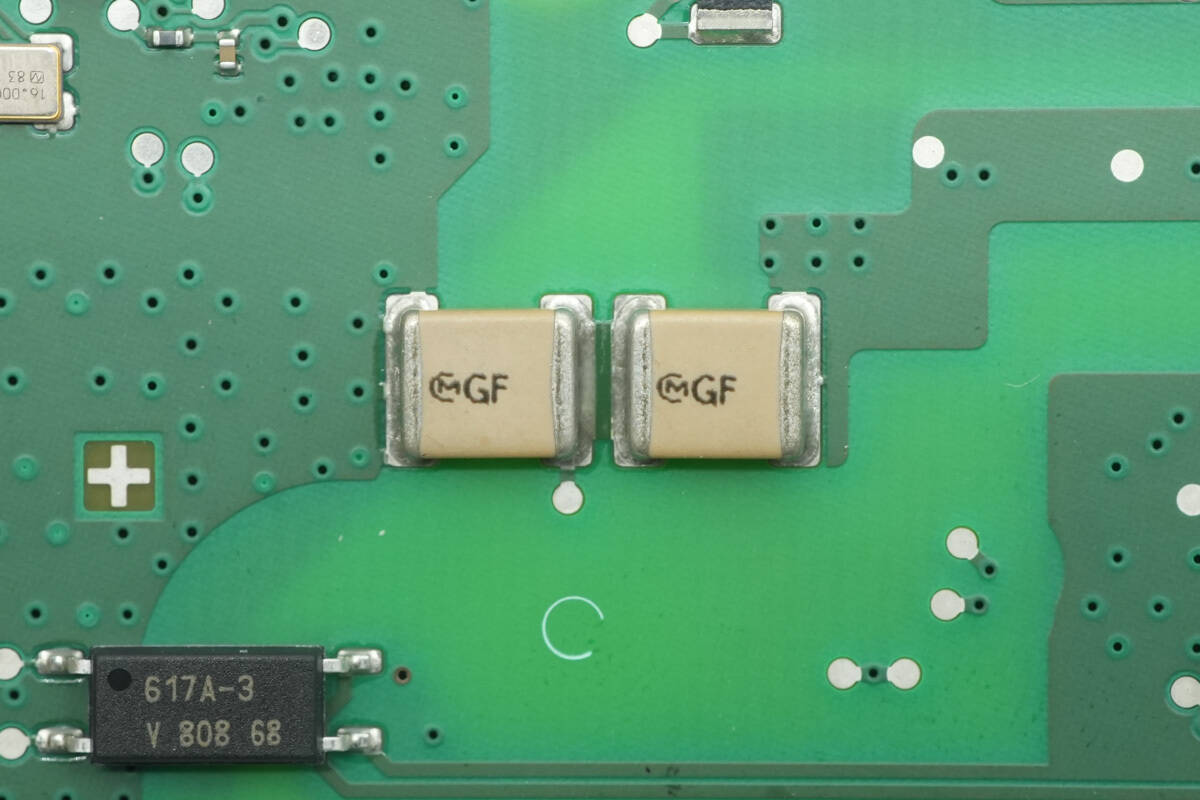
The SMD Y capacitors are from MURATA, with two units connected in series to increase the voltage rating.
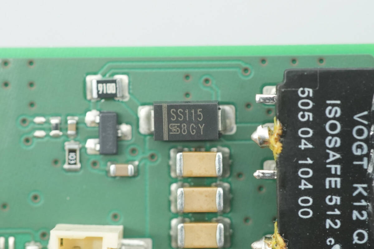
The rectifier is from TSC, model SS115, rated 150 V 1 A, in an SMA package.
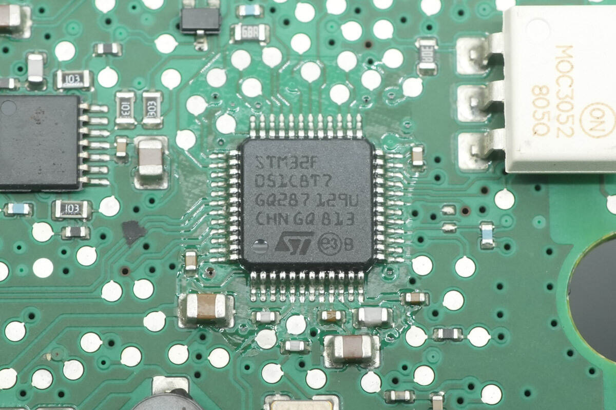
The MCU is from STMicro, model STM32F051C8T7, integrating an ARM Cortex-M0 CPU with a 48 MHz clock. It features 64 KB Flash and 8 KB SRAM, supports motion control and CEC functions, operates over a temperature range of –40 °C to 105 °C, and comes in an LQFP48 package.
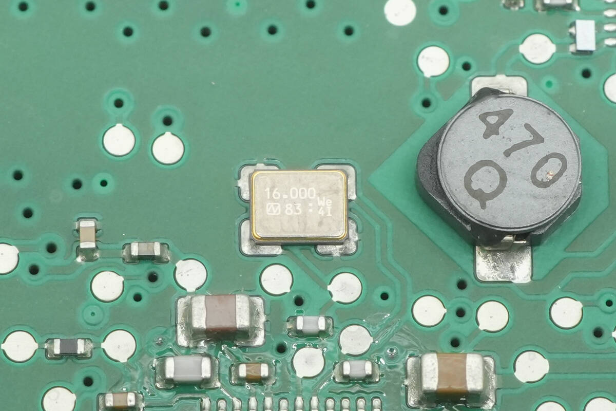
Close-up of a 16.000 MHz crystal oscillator.
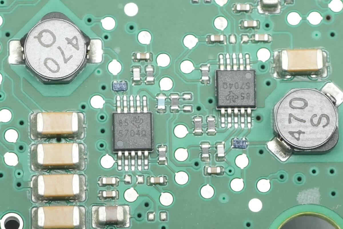
The buck converter ICs are from TI, marked 5704Q, model TPS57040-Q1. They are automotive-grade, 42 V input, 500 mA output buck converters, compliant with automotive application requirements, and come in an HVSSOP10 package.
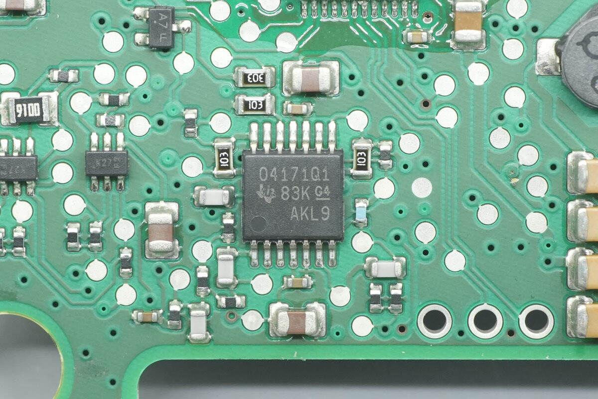
The operational amplifier is from TI, marked O4171Q1, model OPA4171-Q1. It is a 36 V single-supply general-purpose op-amp designed for cost-sensitive automotive systems, compliant with automotive application requirements, and comes in a TSSOP14 package.
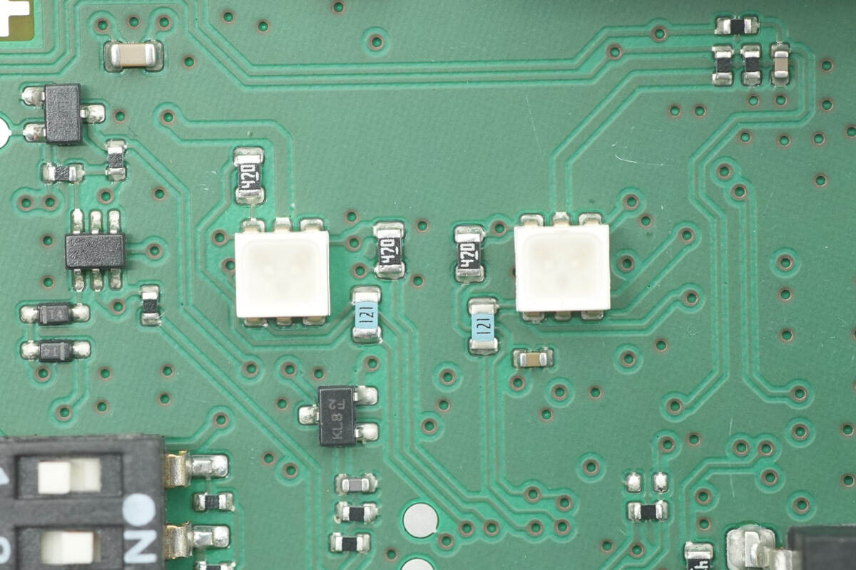
Two SMD LEDs are used for status indication.
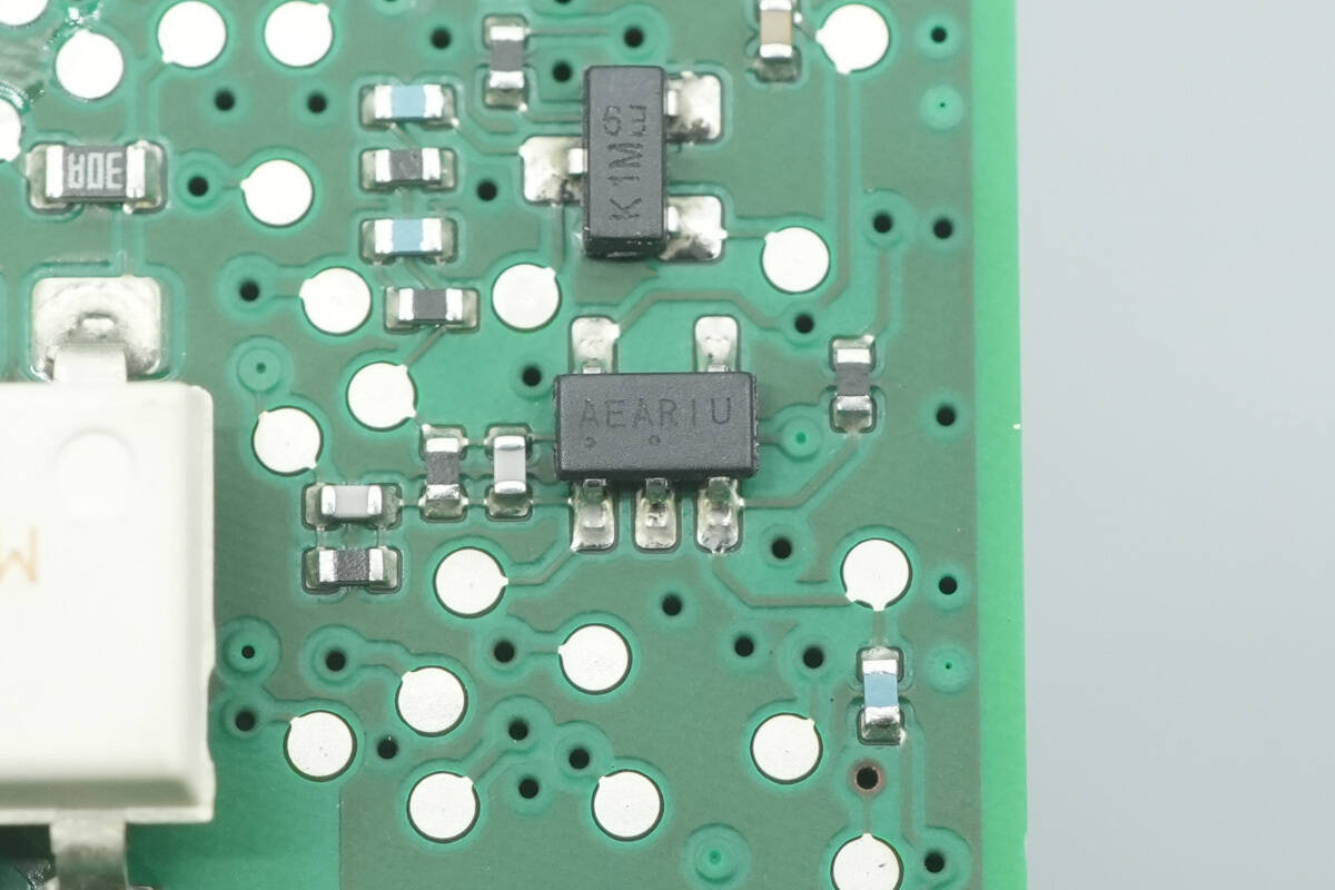
A chip marked “AEA”.
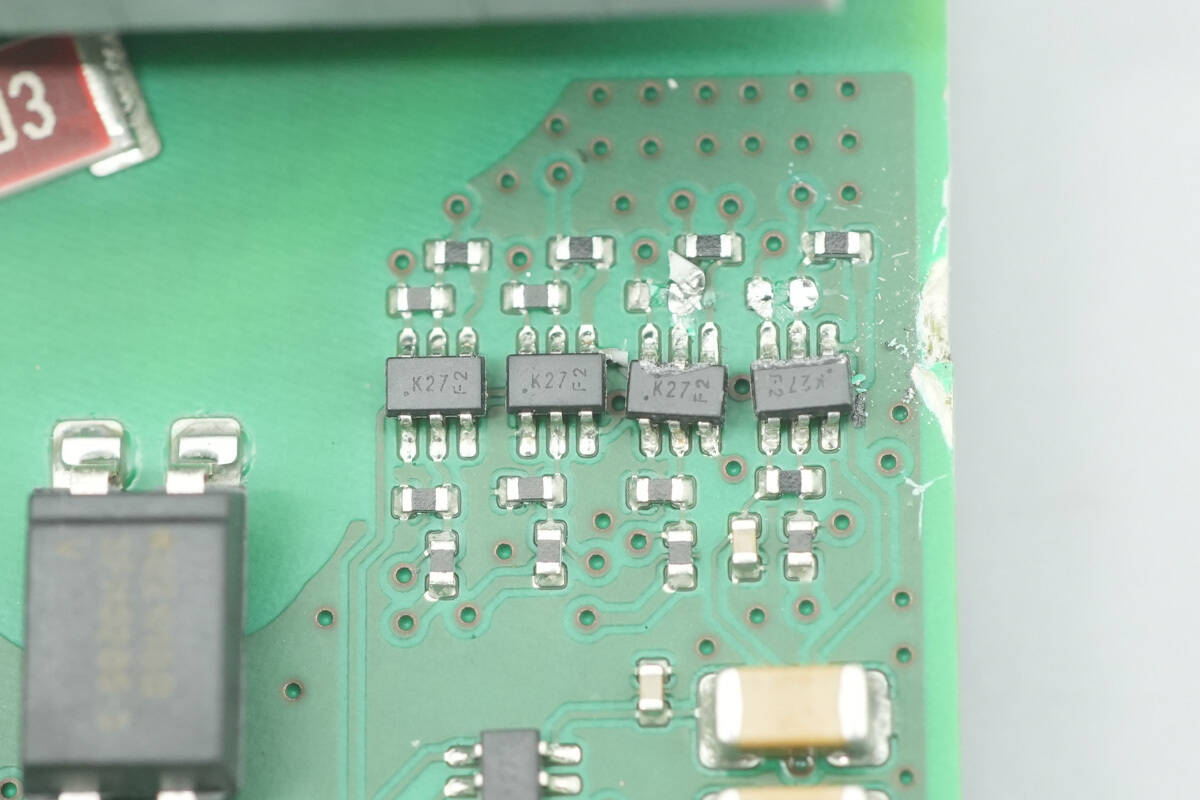
Close-up of dual transistors marked “K27”.
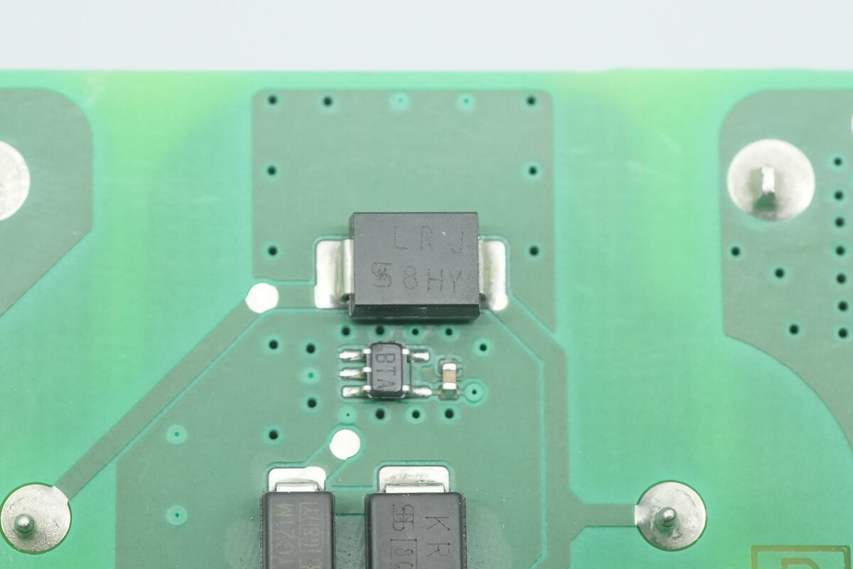
The TVS diode is from TSC, marked LRJ, model P6SMB30A, and comes in an SMB package.
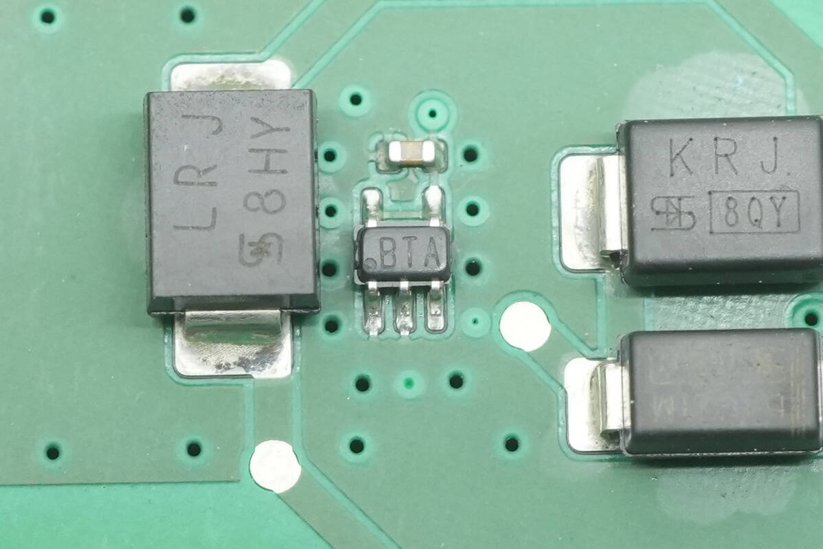
Close-up of a chip marked “BTA”.
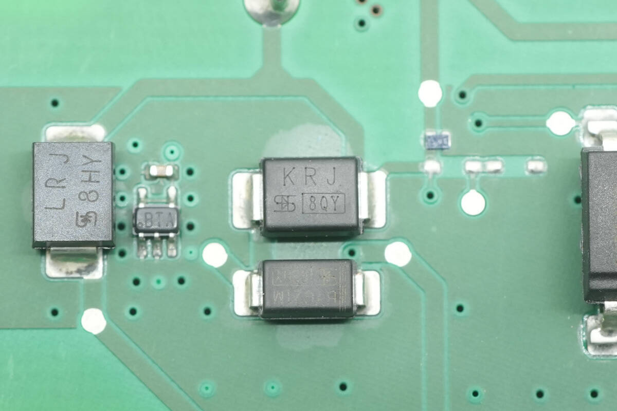
The TVS diode is from TSC, marked KRJ, model P6SMB11A, and comes in an SMB package.
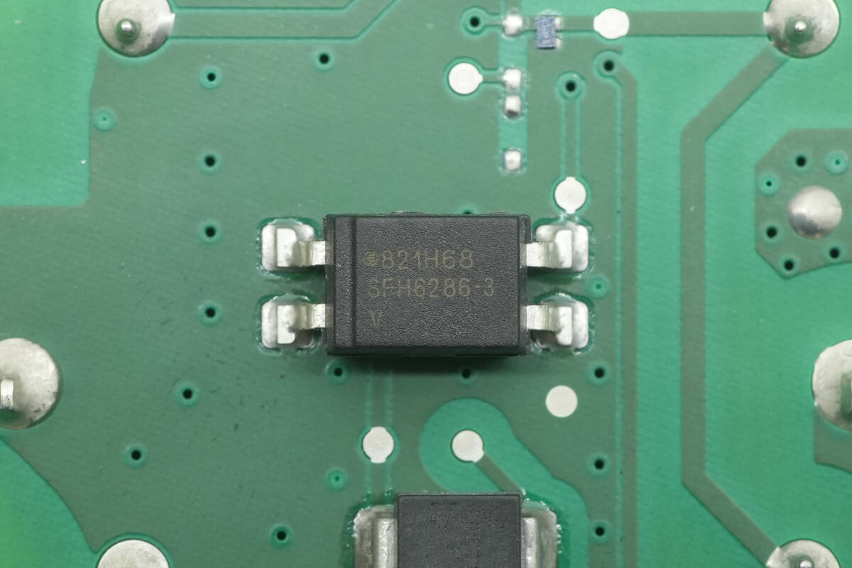
The optocoupler is from VISHAY, model SFH6286-3T, featuring a transistor output.
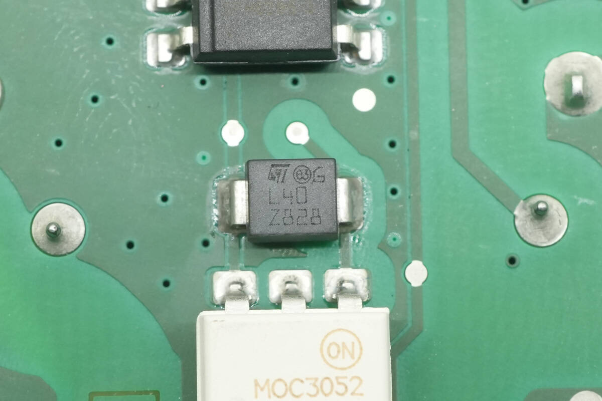
The TVS diode is from STMicro, marked L40, and comes in an SMB package.
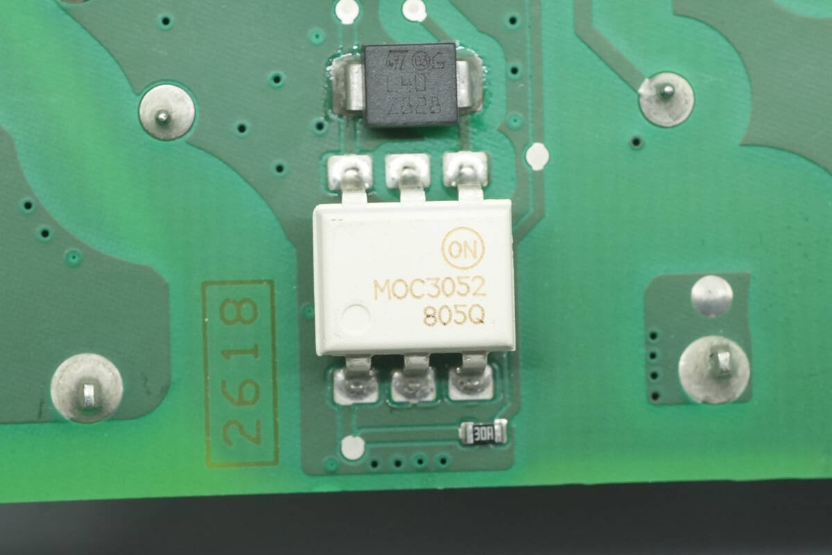
The optocoupler is from onsemi, model MOC3052M, a triac-output optocoupler.
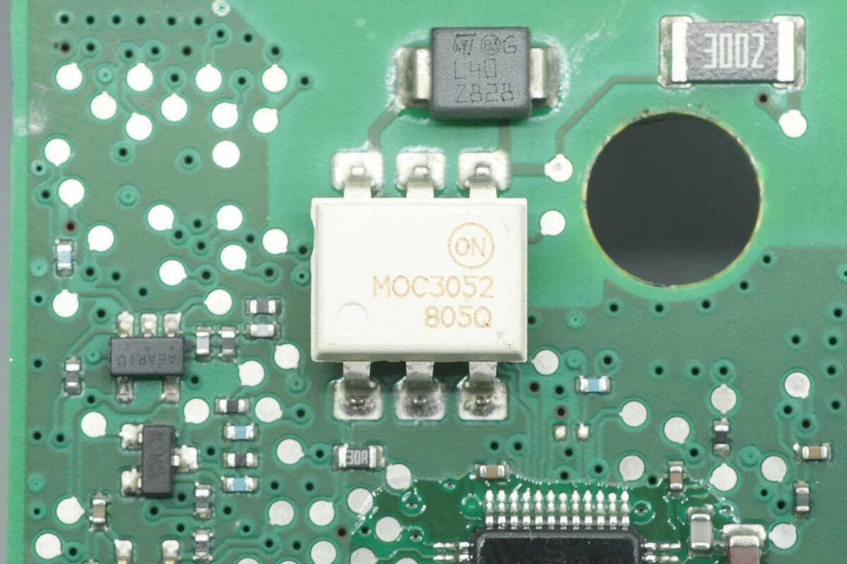
Another optocoupler of the same model is used.
Close-up of the current transformer used for leakage current detection.
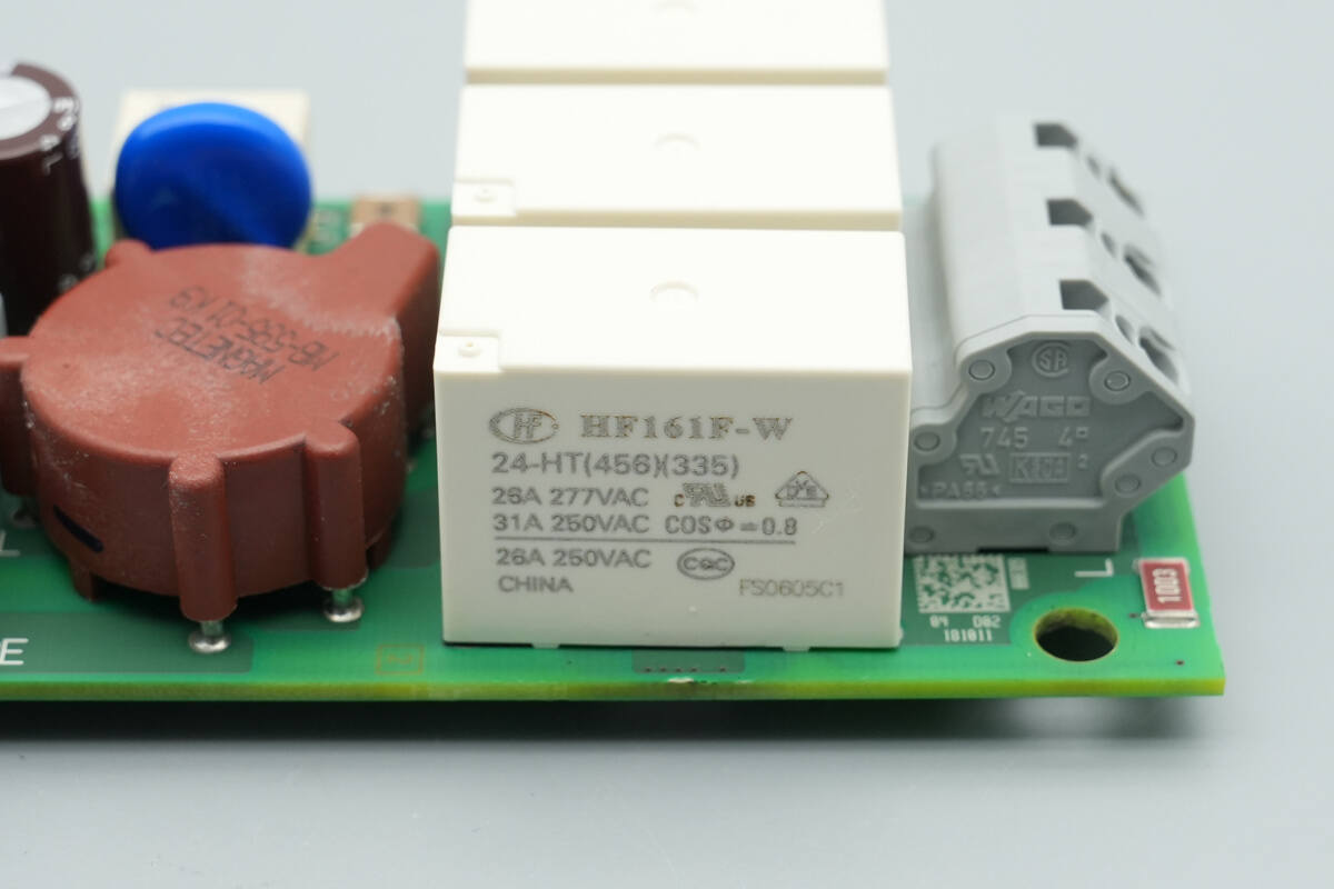
The relay is from HONGFA, model HF161F-W/24-HT, a solar relay with a contact switching capacity of 31 A, featuring one built-in normally open contact and a 24 V coil voltage.
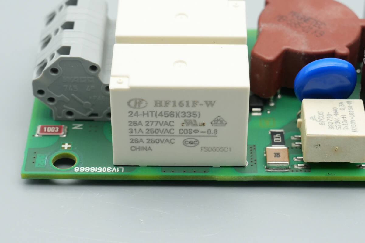
Three relays of the same model are used, controlling the live, neutral, and ground lines, respectively.
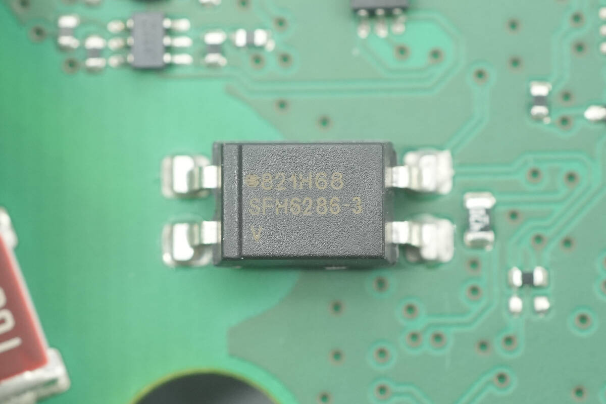
The optocoupler is from VISHAY, model SFH6286-3T.
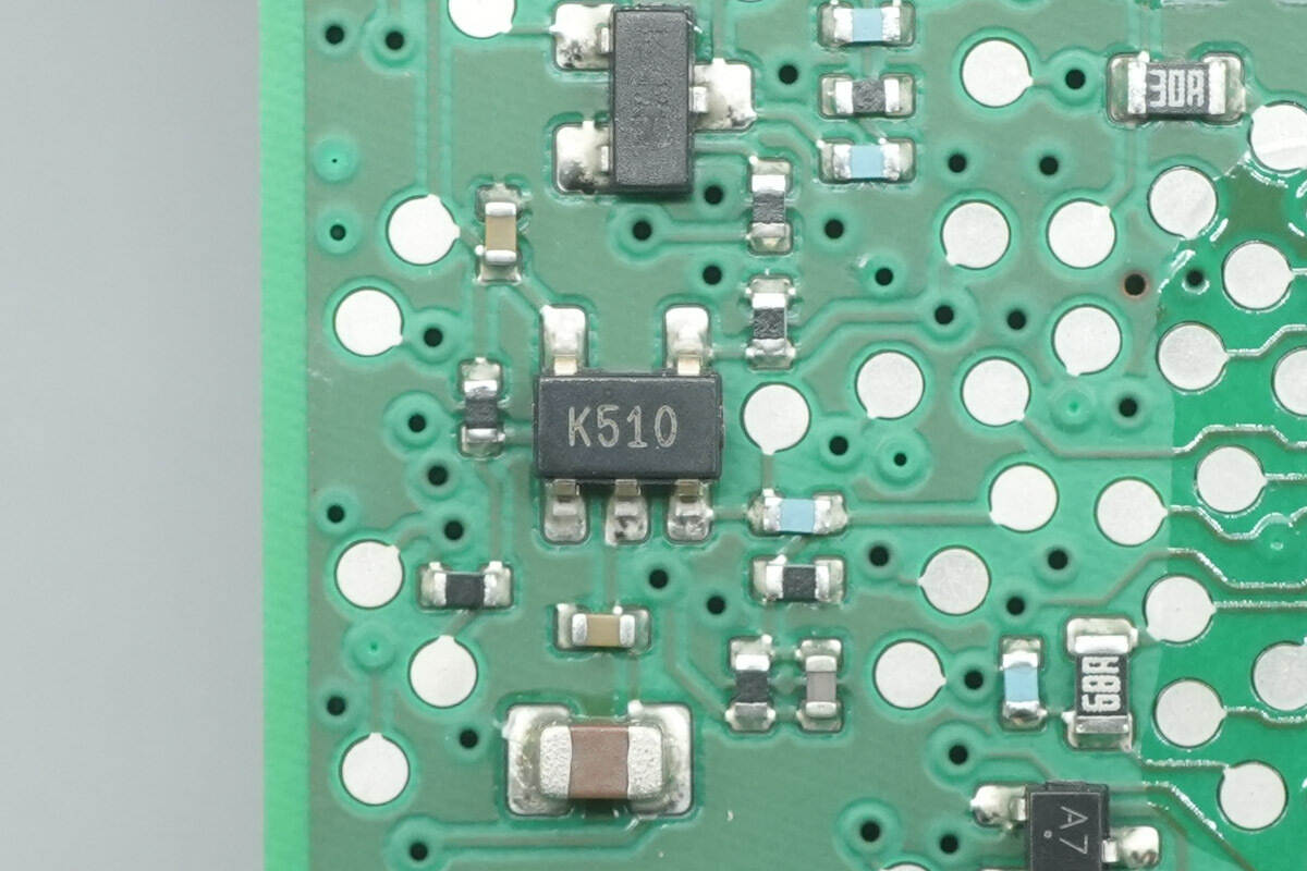
The voltage comparator is from STMicro, marked K510, model TS391IYLT. It is a low-power, single-channel voltage comparator in a SOT23-5 package.
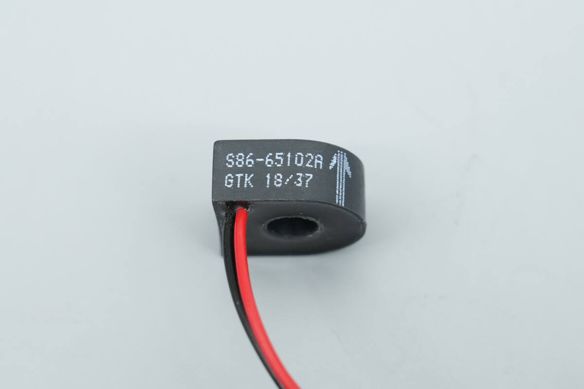
Close-up of the current transformer used for charging current detection.

The interior of the charging connector is filled and sealed with potting compound.

Well, those are all components of the MENNEKES EV Charging Cable.
Summary of ChargerLAB
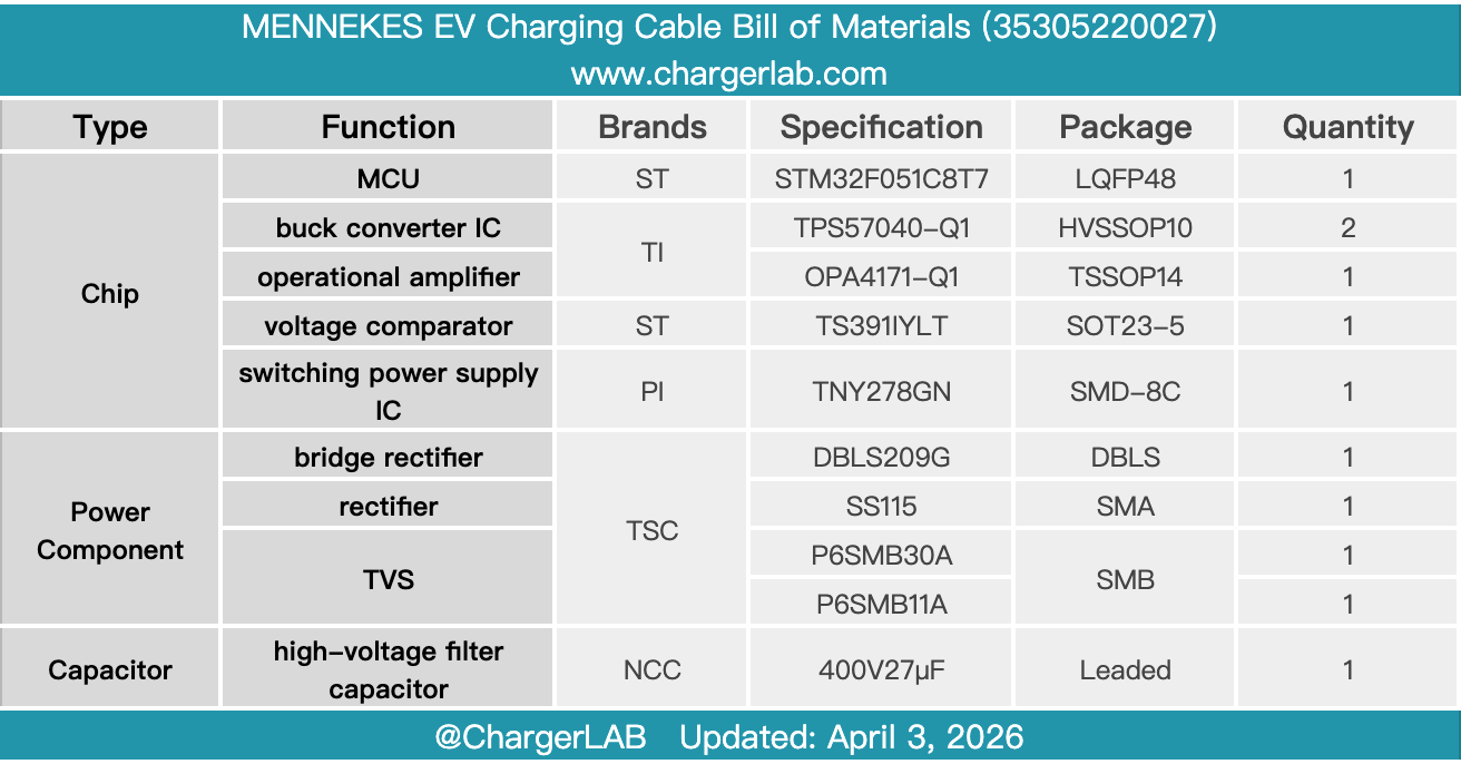
Here is the component list of the MENNEKES EV Charging Cable for your convenience.
This charging connector features a split design with a 10 A plug, supporting an 8 A charging current and a charging power of 1760 W. Its total length is approximately 4.5 m, with a yellow cable for easy identification. The connector provides basic charging protection and status indication, suitable for daily use and convenient for carrying in a vehicle.
After taking it apart, we found that the charging control box is secured with screws, and the internal PCBA module is also mounted with screws, with wires connected via plug-in connectors. The control box uses an STMicro STM32F051C8T7 MCU for parameter acquisition and protection control, paired with a TI OPA4171-Q1 operational amplifier.
Inside the control box, the switching power supply IC is from Power Integrations, model TNY278GN, while the buck converter uses a TI TPS57040-Q1. Current transformers are installed for current measurement, and HONGFA relays are used for charging control. The control box features a sealed design to protect the PCBA module, with neat workmanship and robust, reliable components.
Related Articles:
1. Teardown of Samsung 5000mAh Qi2 Magnetic Wireless Power Bank (EB-U2500)
2. Teardown of Huawei P30
3. Teardown of OPPO 50W AirVOOC Magnetic Wireless Charger (OAWV09)