Introduction
We have received a Huntkey 2000W Platinum-rated server power supply. It supports 100-127V AC input with an output power of 1000W. When the input voltage is 200-240V AC, it reaches its rated output power of 2000W. The rated output voltage is 12V, the standby power output is 12V, and the rated output current is 3A.
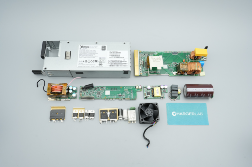
The input side features a cooling fan, power socket, and indicator light, while the output side has a gold finger connector. Internally, it uses a PFC+LLC architecture and meets the 80 PLUS Platinum efficiency standard. Next, let’s take it apart to examine its internal components and structure.
Product Appearance
It uses a metal casing secured with screws.
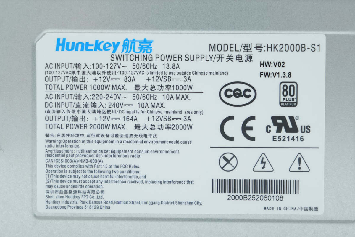
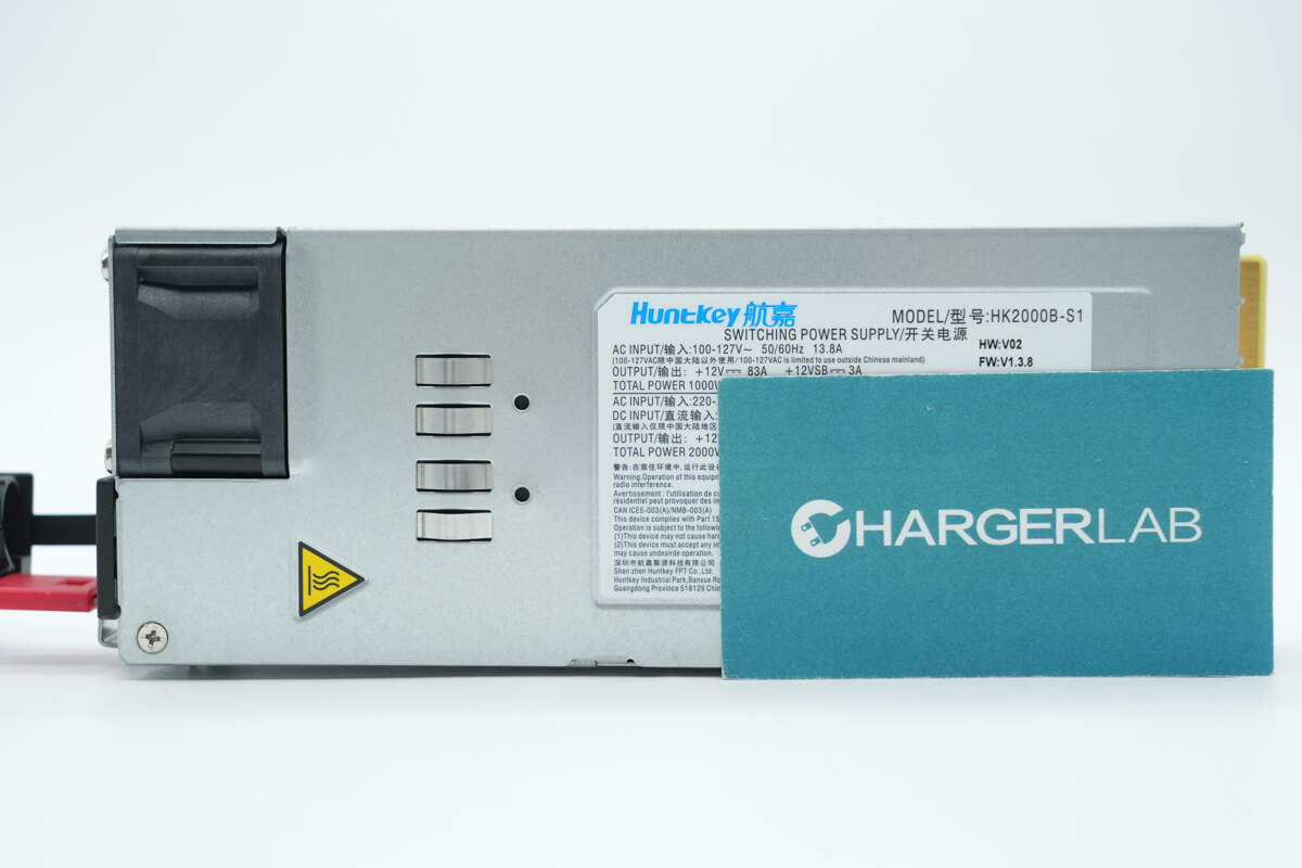
Model: HK2000B-S1
Input: 100-127V\~ 50/60Hz 13.8A
Output: +12V 83A, +12VSB 3A
Maximum total power: 1000W
Input: 200-240V\~ 50/60Hz 10A MAX
DC input: 240V 10A MAX
Output: +12V 164A, +12VSB 3A
Maximum total power: 2000W
The power supply is certified by CQC, CE, and UL, and meets the 80 PLUS Platinum efficiency standard.
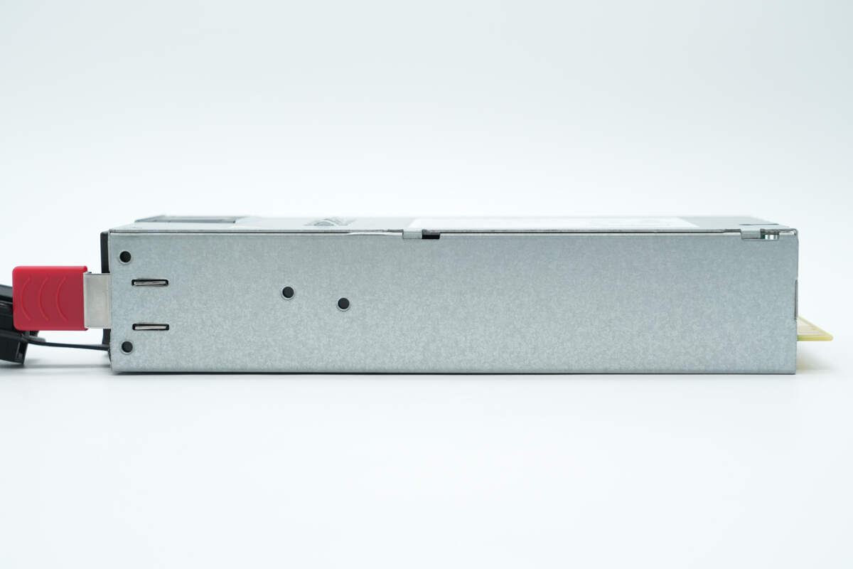
The casing is equipped with spring clips for grounding.
The cooling fan is secured with screws.
The other side is also equipped with grounding spring clips.
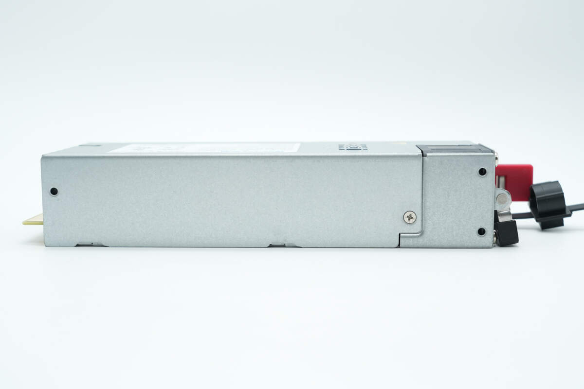
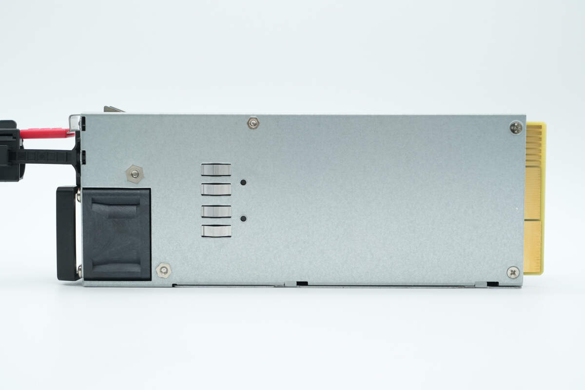
There is a mounting screw on this side.
The other side is equipped with a handle.
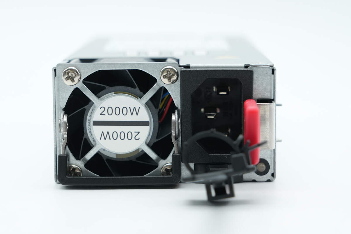
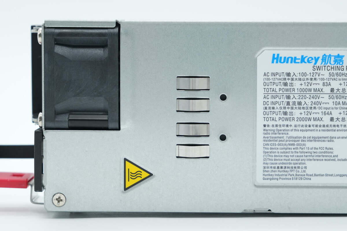
The input side features a carrying handle, cooling fan, power indicator light, three-prong socket, and a release handle.
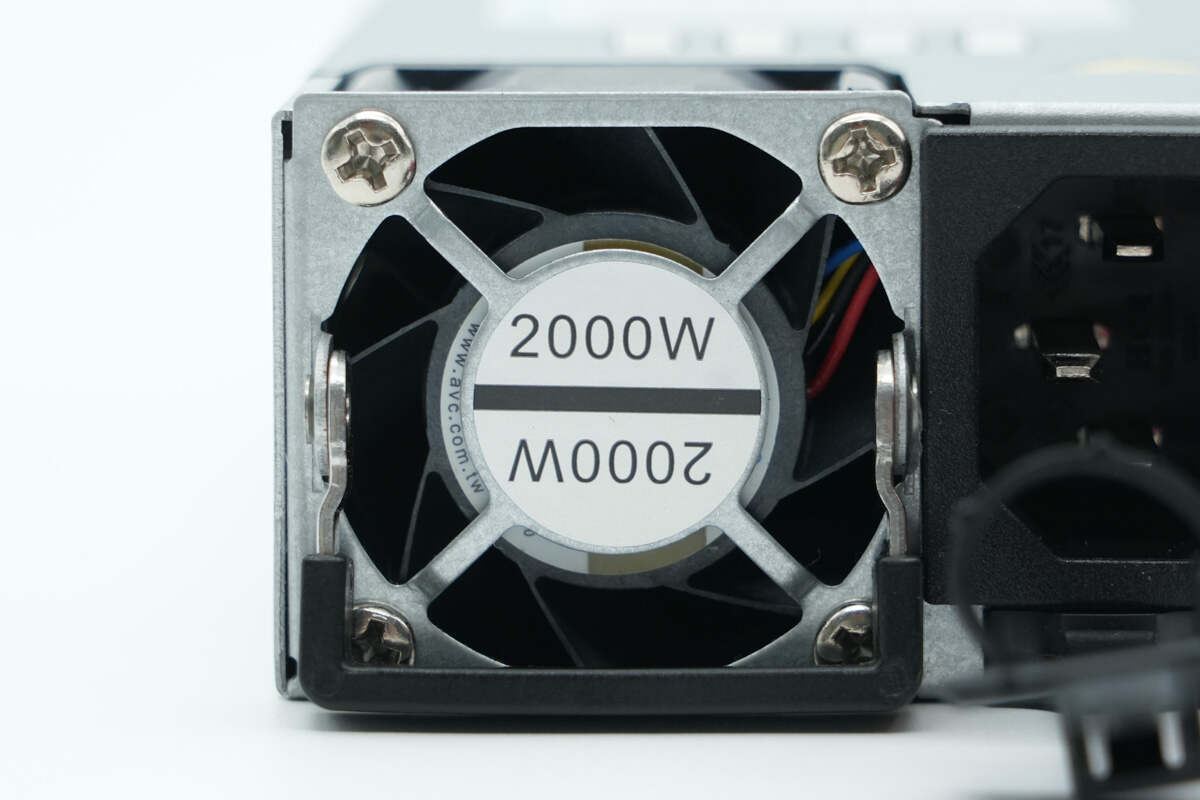
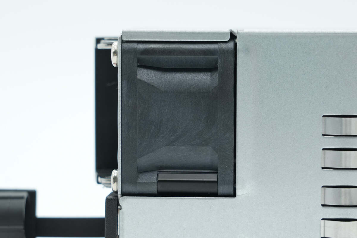
The fan has a protective cover and is labeled with the power supply’s output wattage.
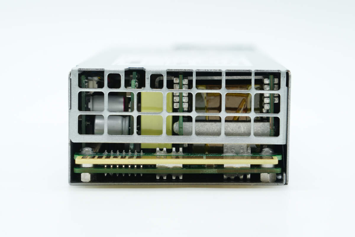
The output side has a ventilation grille, and the gold finger connector is connected via PCB soldering.
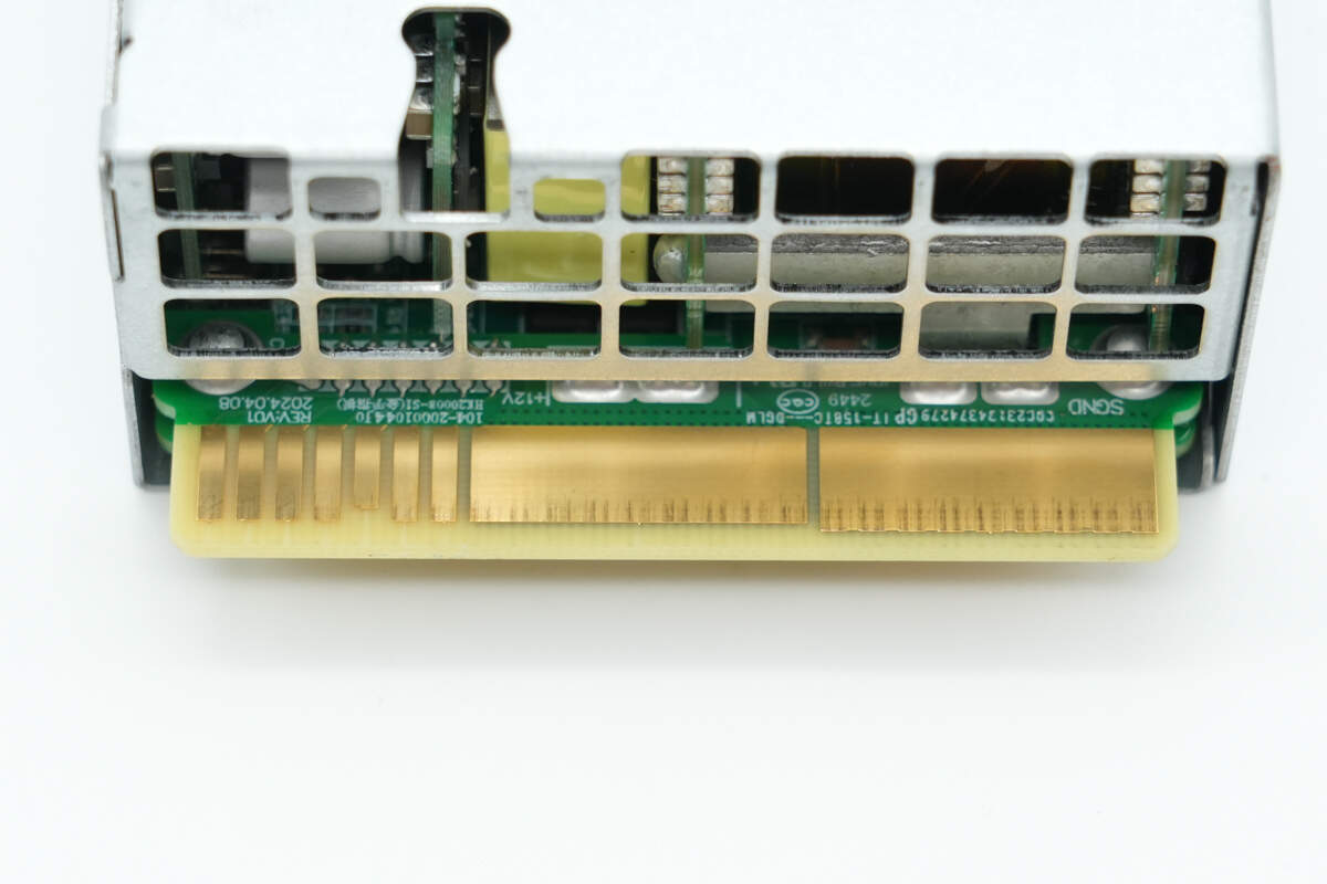
Close-up of the gold finger connector.
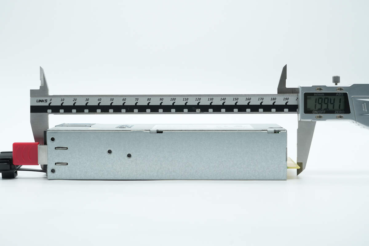
The length of the power supply is about 200 mm (7.87 inches).
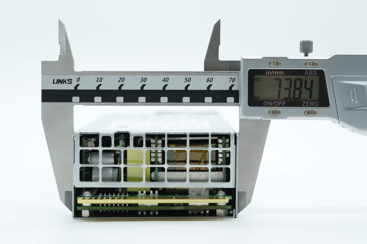
The width is about 73.8 mm (2.91 inches).
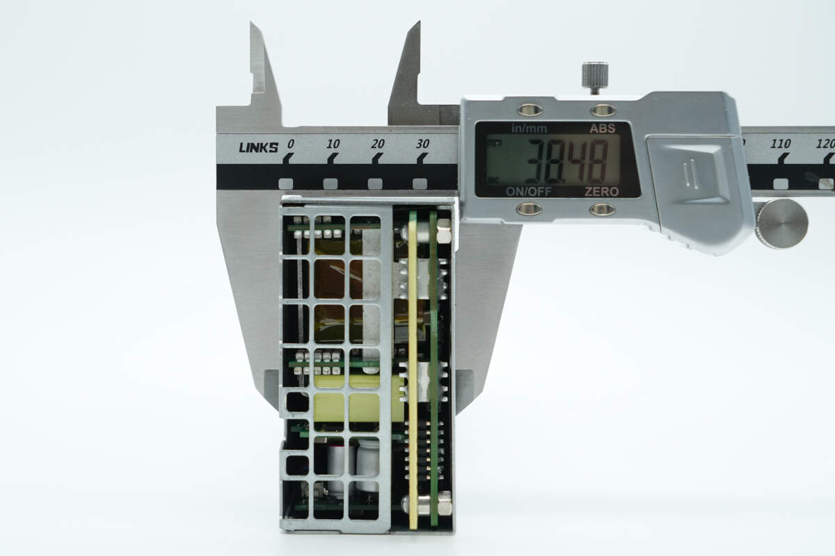
The thickness is about 38.5 mm (1.52 inches).
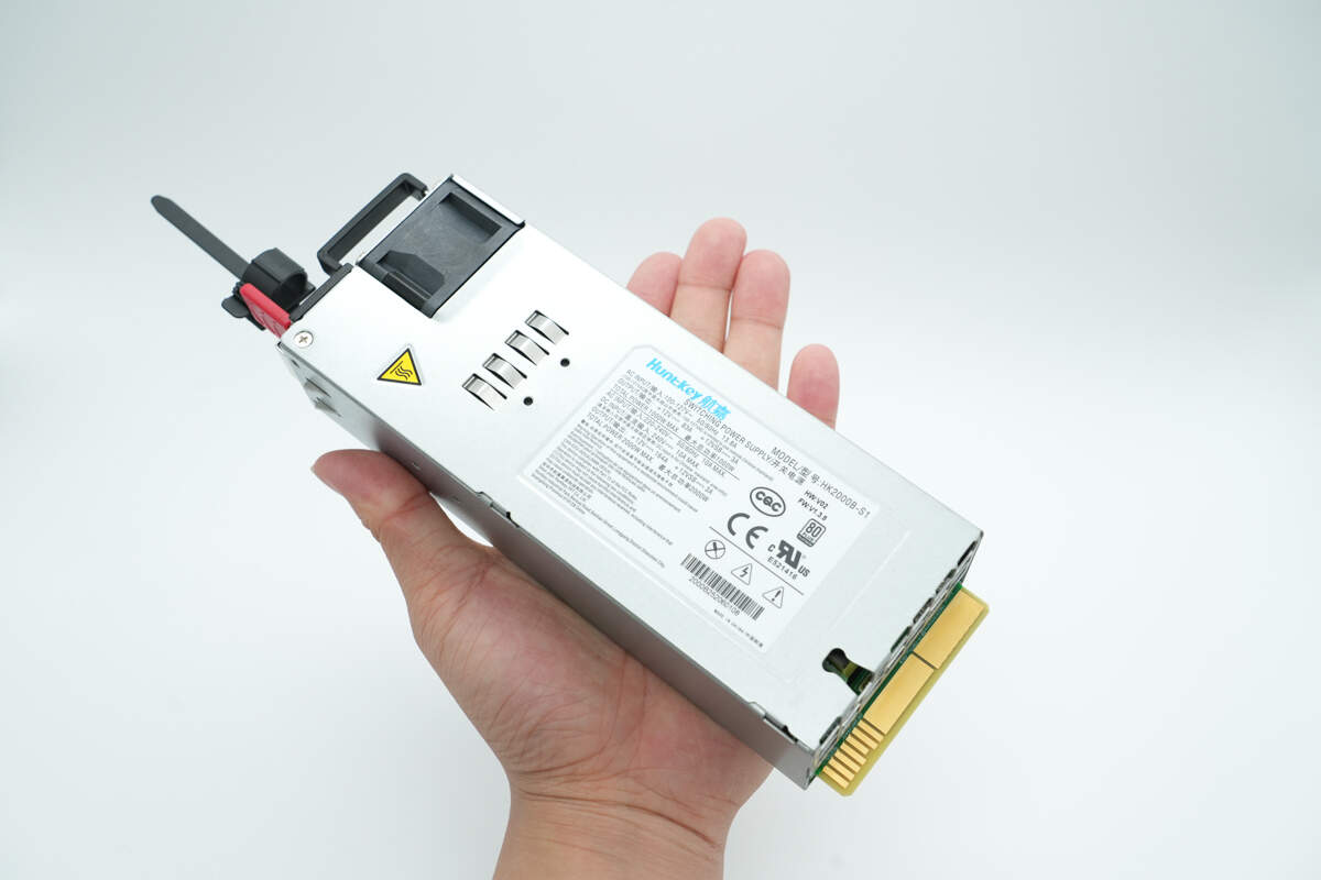
That's how big it is in the hand.
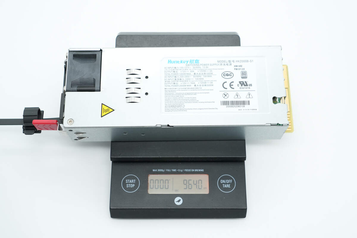
The weight is about 964 g (2.125 lb).
Teardown
Next, let's take it apart to see its internal components and structure.
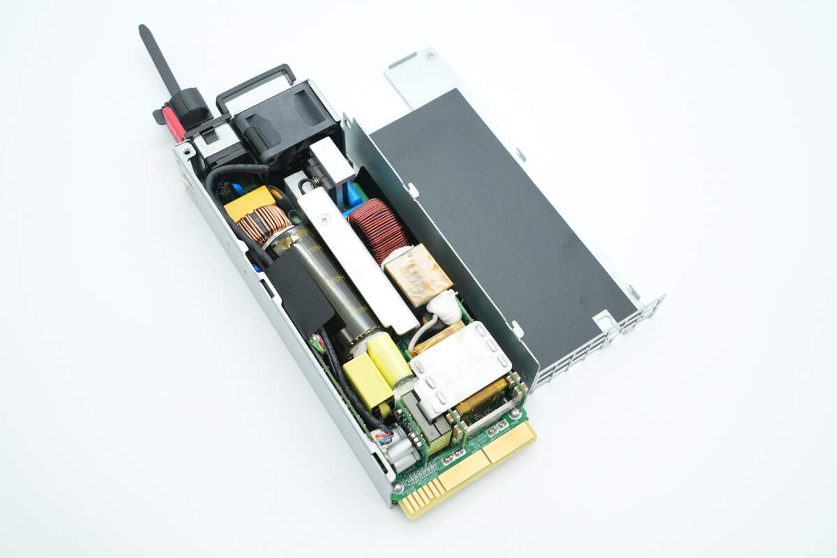
Unscrew the screws and remove the top cover. Inside the top cover, there is an insulating Mylar sheet.
The PCBA module is secured inside the casing with screws.
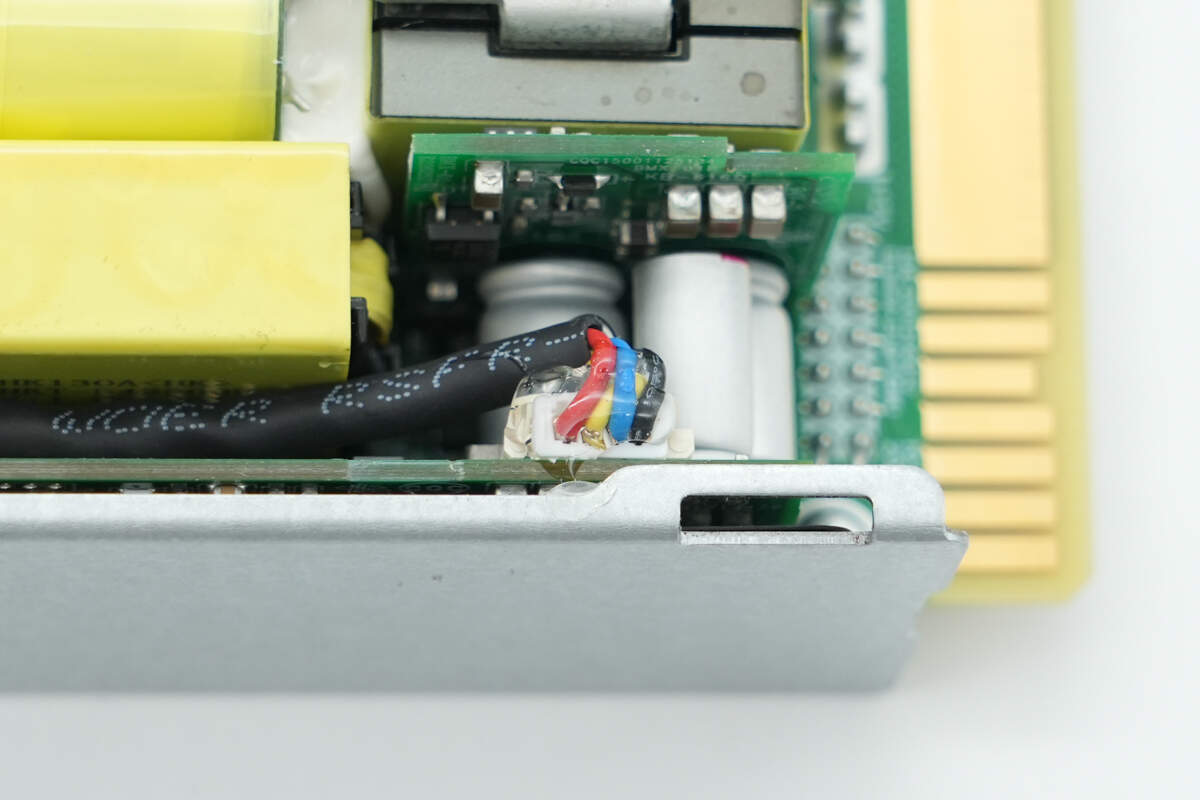
The power indicator light is connected via a plug connector.
The cooling fan is also connected via a plug connector.
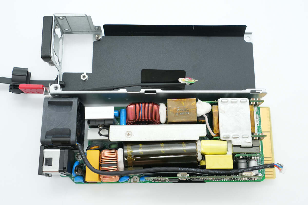
Unscrew the screws to remove the PCBA module. On the other side, inside the casing, there is also a black insulating Mylar sheet.
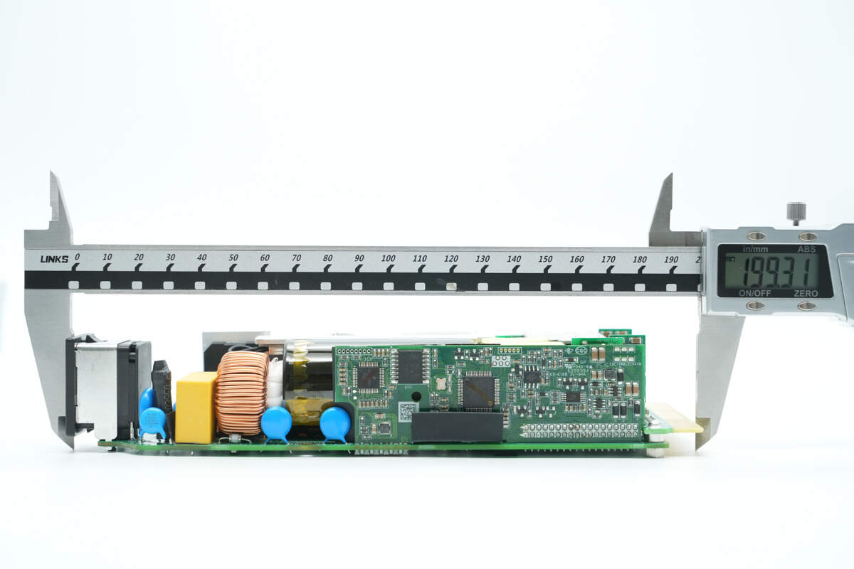
The length of the PCBA module is about 205 mm (7.83 inches).
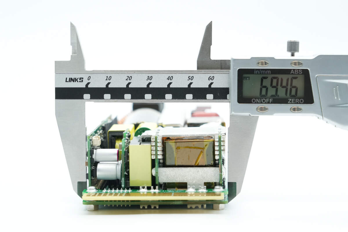
The width is about 69.5 mm (2.74 inches).
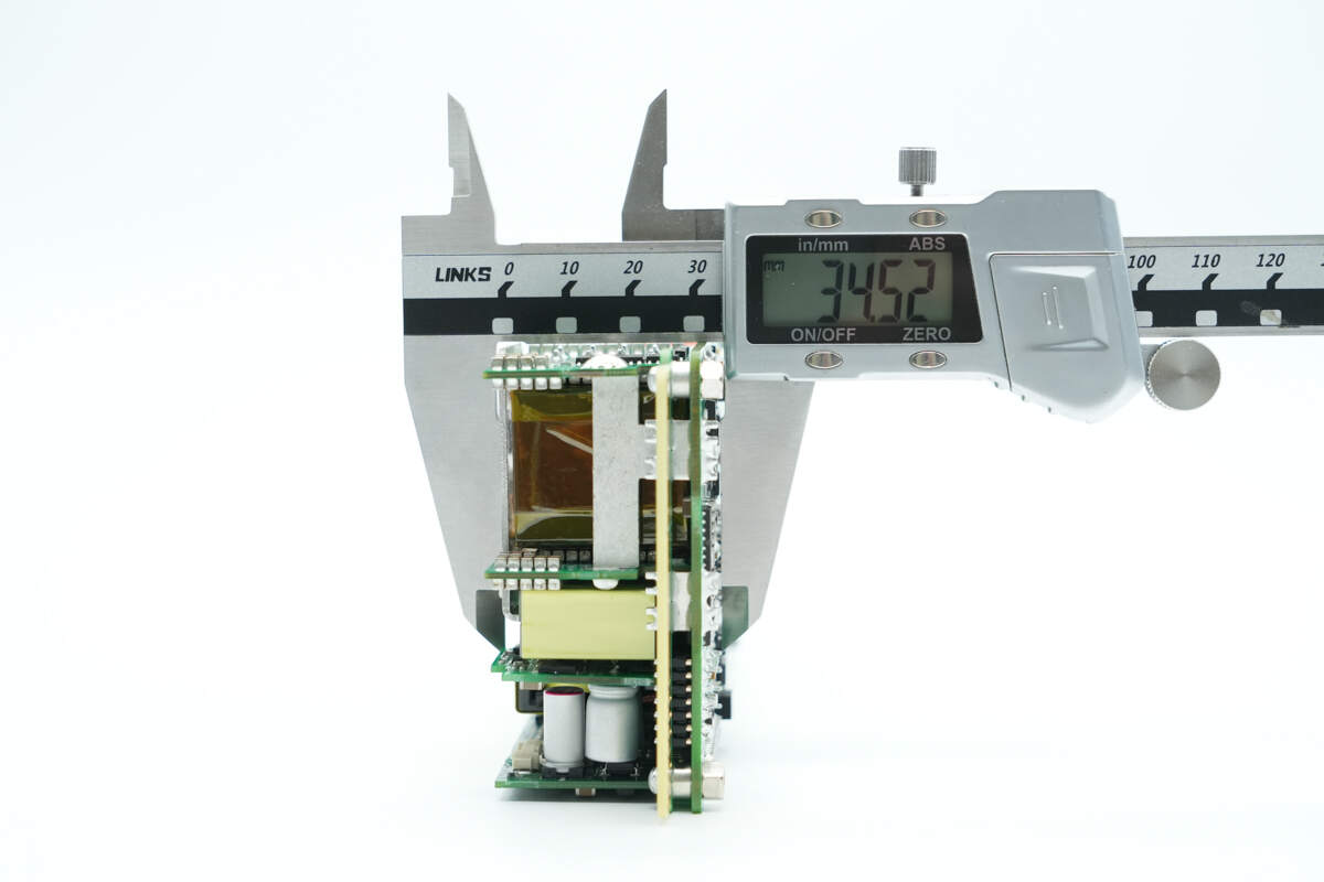
The thickness is about 34.5 mm (1.36 inches).
The PCBA module is composed of multiple small PCBs soldered together, with adhesive applied between components for reinforcement.
The transformer is connected via thick copper strips that are soldered in place.
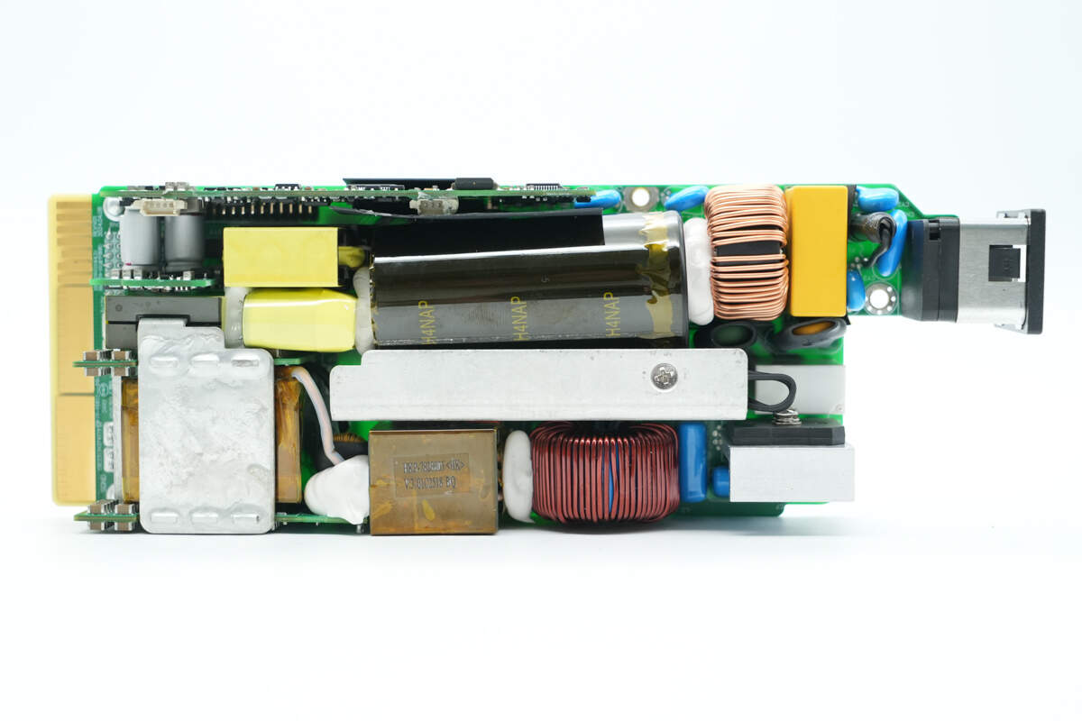
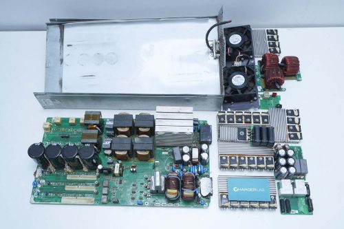
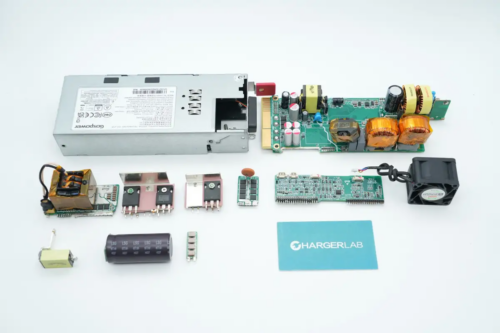
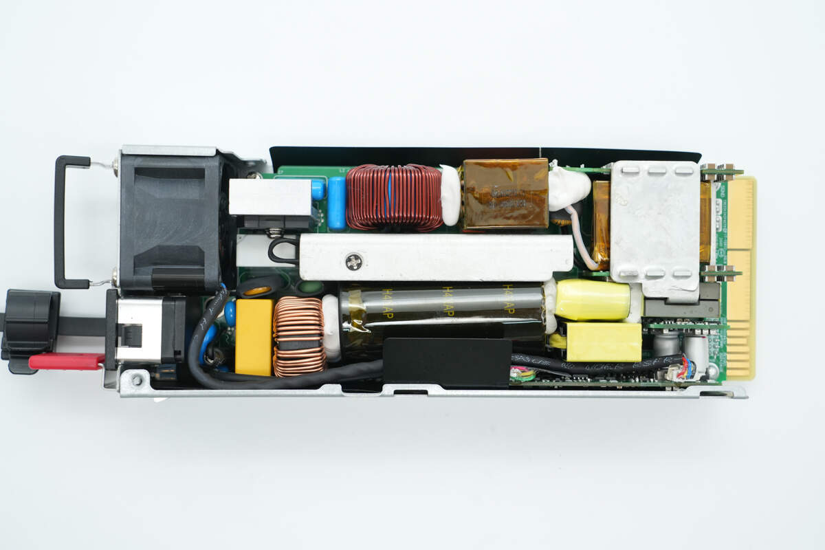
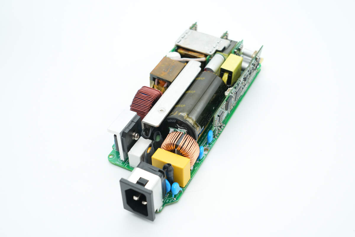
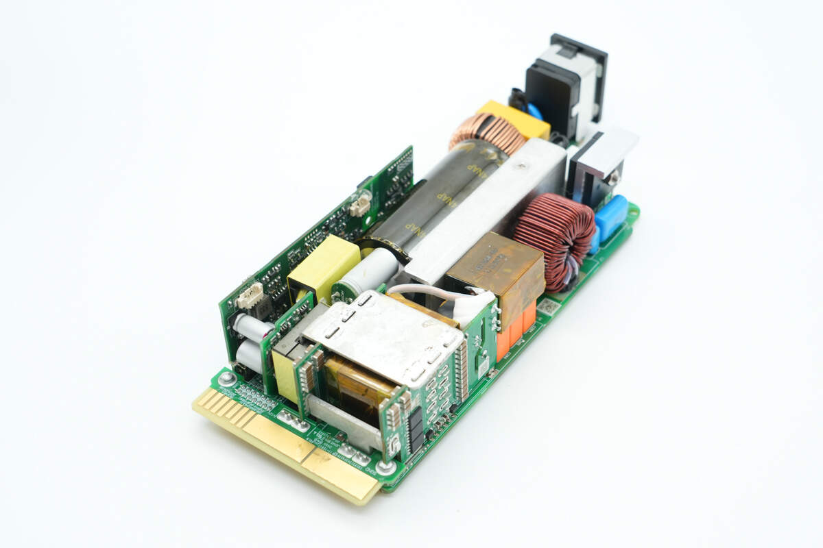
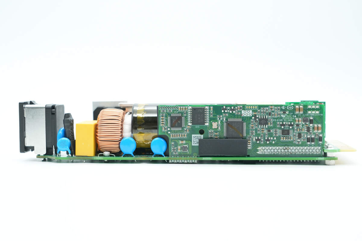
The front side of the PCBA module, at the upper right corner, is the AC input section. It includes components such as the input socket, fuse, safety-rated X2 capacitor, Y capacitor, common-mode choke, varistor, and thermistor. Below are a relay and a bridge rectifier with a heatsink. To the left are film capacitors and a PFC boost inductor.
To the left of the PFC boost inductor is a resonant inductor. The central heatsink cools the PFC MOSFETs, PFC diodes, and LLC MOSFETs. Above this is a high-voltage filter capacitor, with the control PCB located at the top. Below are the standby power transformer, filter capacitors, and the main transformer.
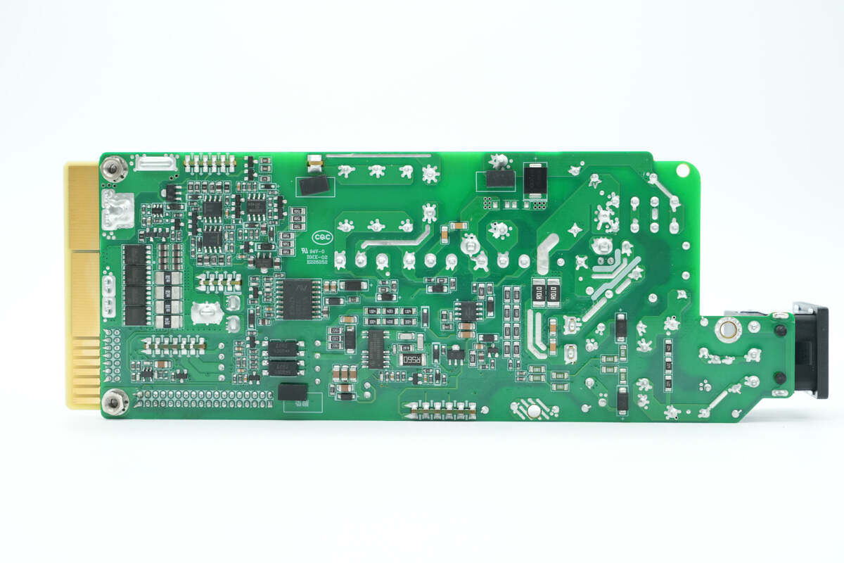
On the back side, there are components such as drivers, isolation drivers, feedback optocouplers, voltage comparators, and output control transistors. There is also a standby power supply chip.
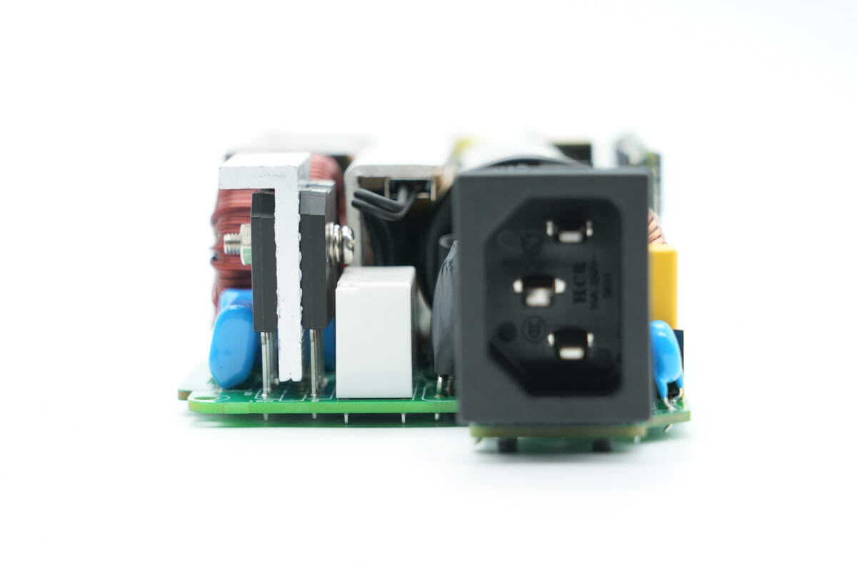
The input side includes a bridge rectifier, relay, and socket.
This side features a fuse, safety-rated X2 capacitors, a common mode choke, and the control PCB.
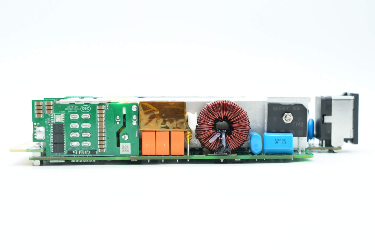
The other side has a synchronous rectification PCB, a resonant inductor, resonant capacitors, a PFC boost inductor, film capacitors, and a bridge rectifier.
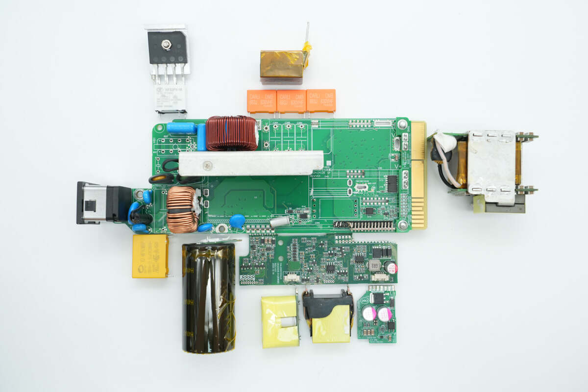
After disassembling the components and examining the PCBA module, it is observed that the power supply uses a PFC combined with an LLC architecture for power output.
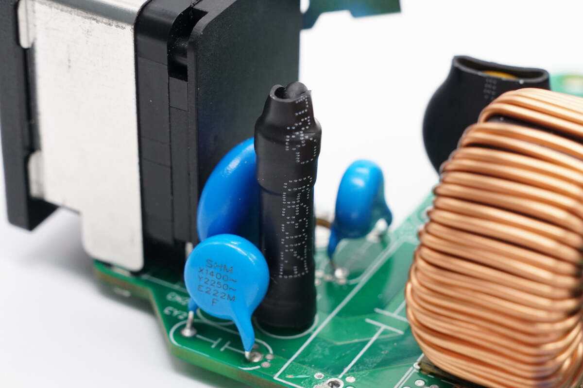
The fuse at the input side is insulated with heat-shrinkable tubing.
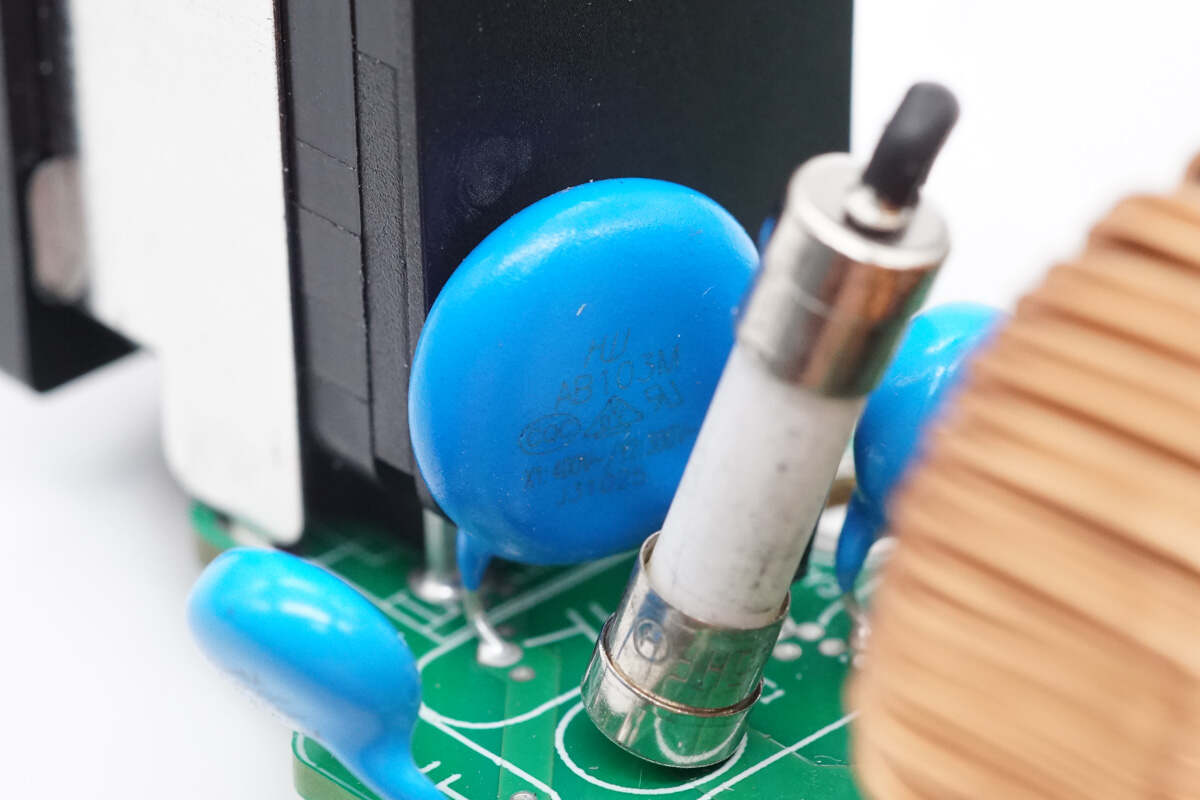
Close-up of the blue safety-rated X2 capacitor.
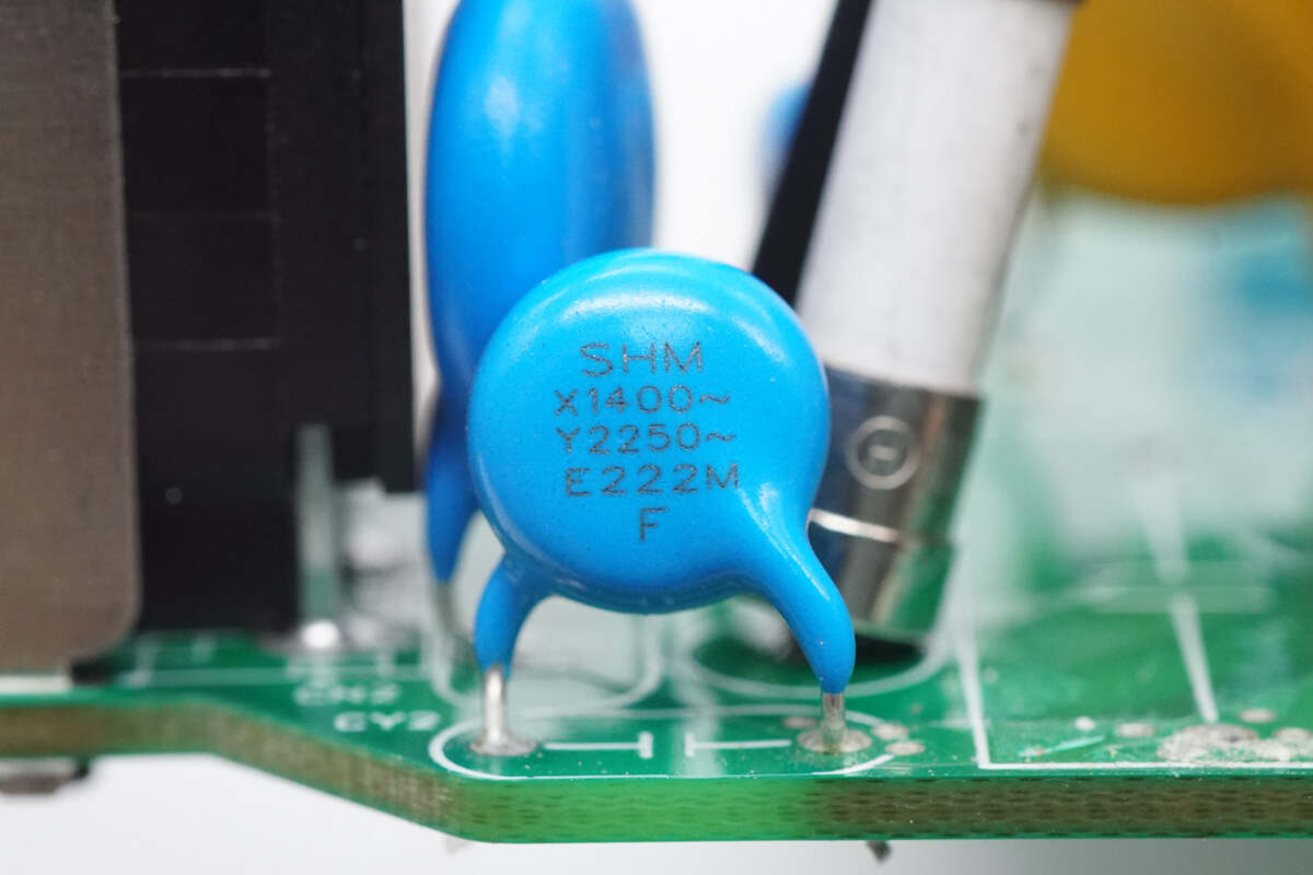
The Y capacitors are manufactured by SHM.
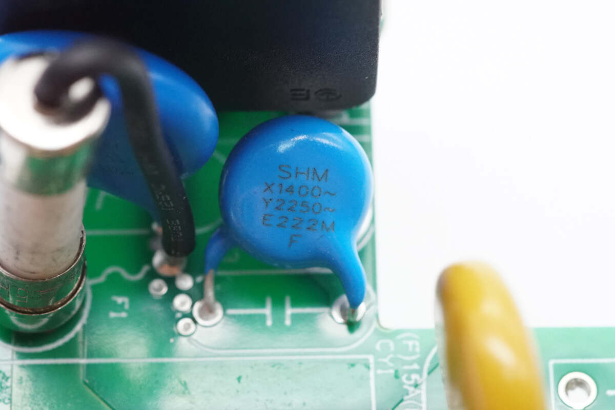
The other Y capacitor has the same specifications.
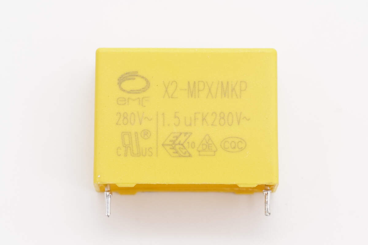
The safety X2 capacitor is from EMF, with a specification of 1.5μF.
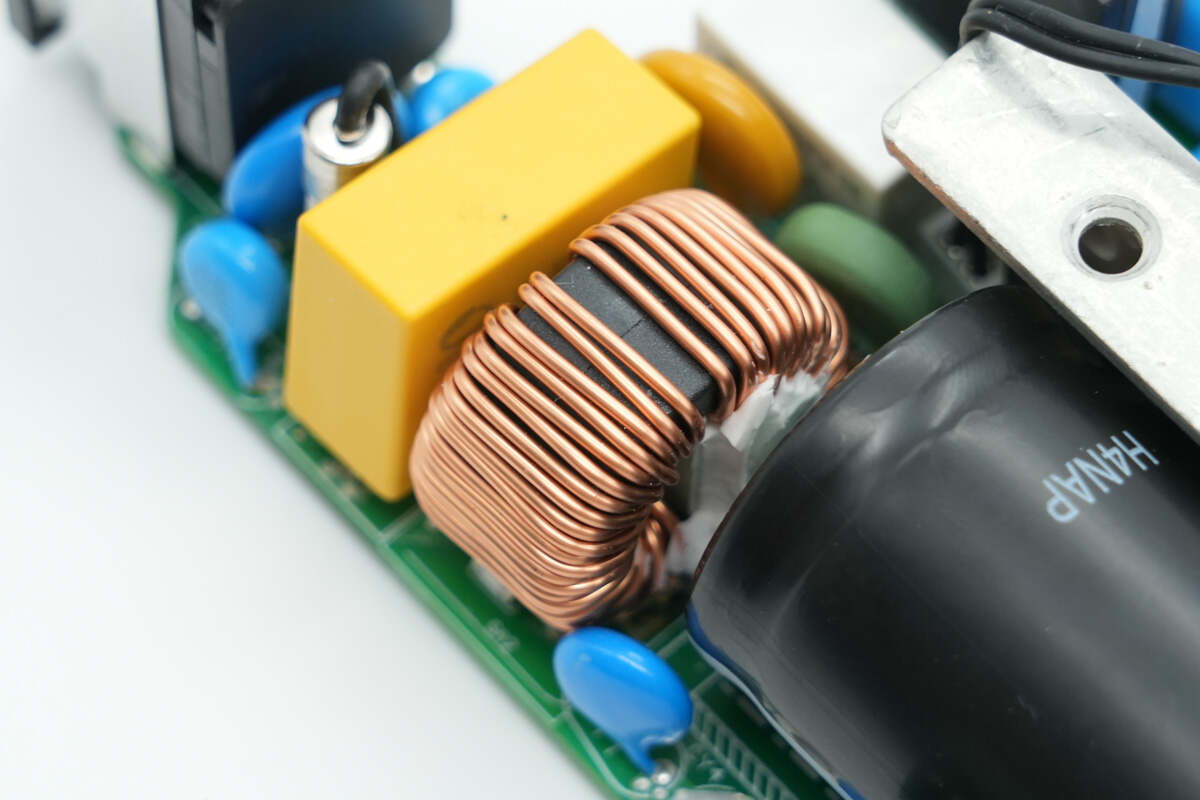
The common mode choke is wound around a magnetic ring and is also insulated with Bakelite.
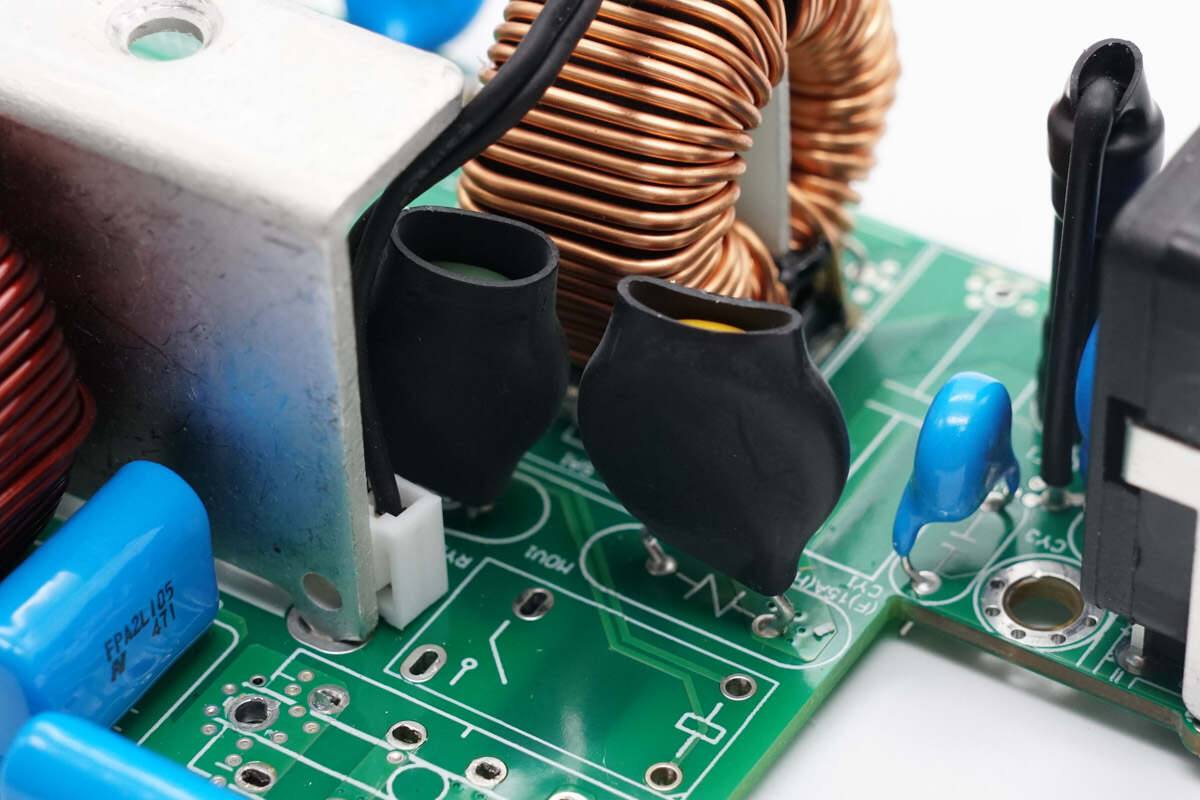
The varistor and NTC thermistor are insulated with heat-shrinkable tubing.
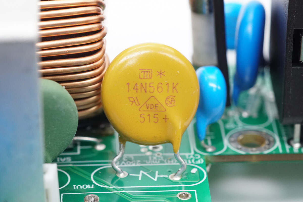
The varistor is from JOYIN, model 14N561K, and is used to absorb overvoltage surges.
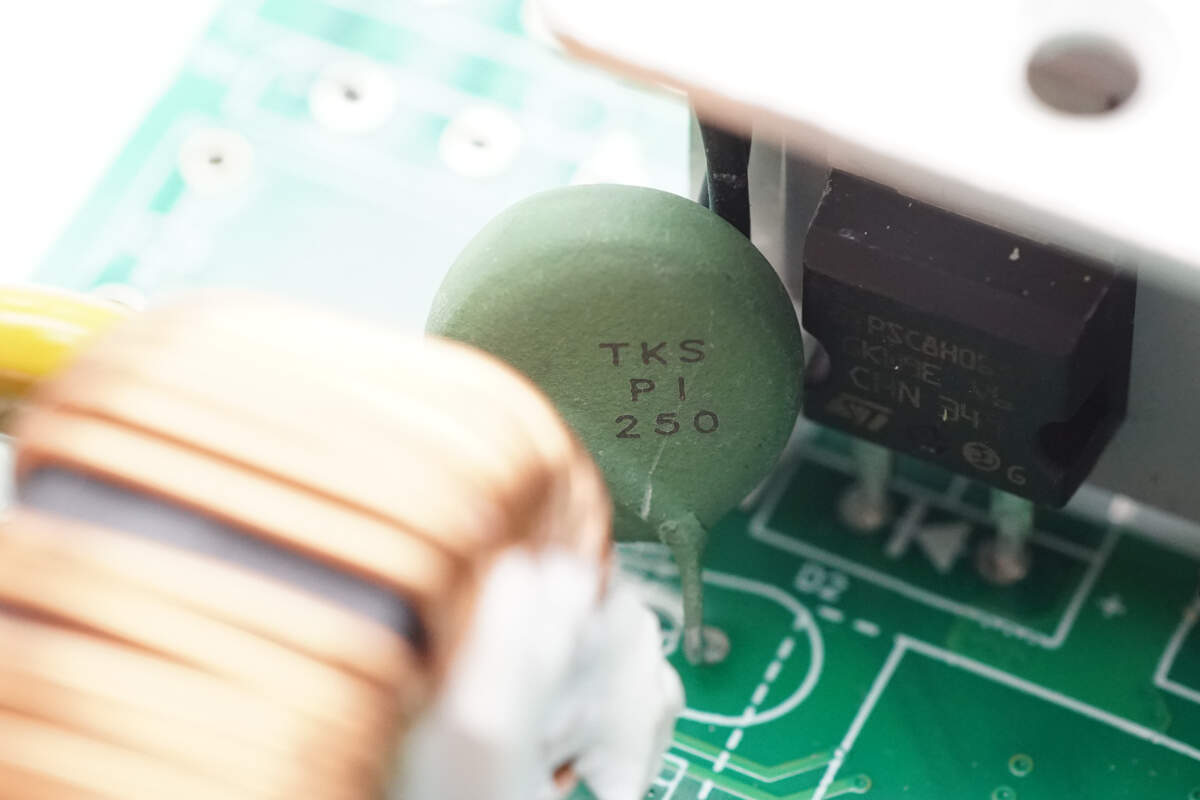
The thermistor is from Thinking, marked with TKS PI 250, and is used to suppress inrush current during power-up.
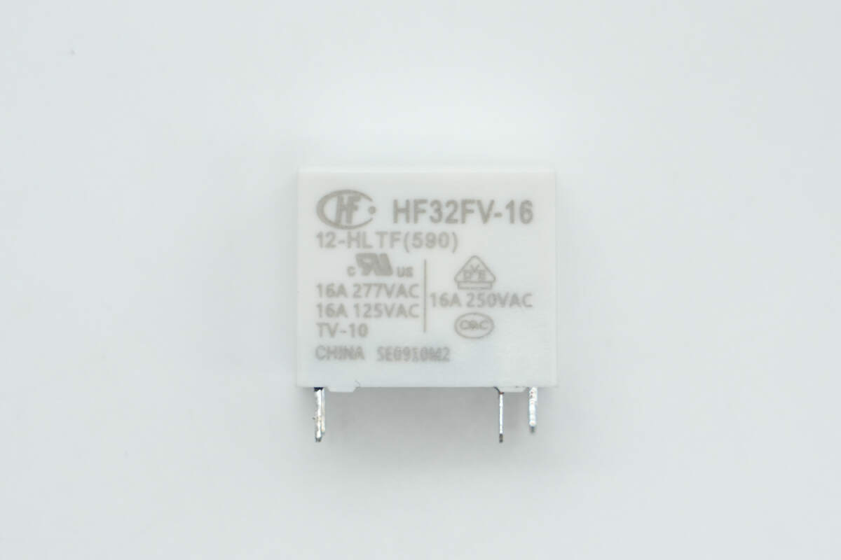
The relay is from HONGFA, model HF32FV-16/12-HLTF. It is an ultra-compact high-power relay with a contact rating of 16A at 250V and a coil voltage of 12V. It is used in series with the thermistor to bypass it and eliminate power loss.
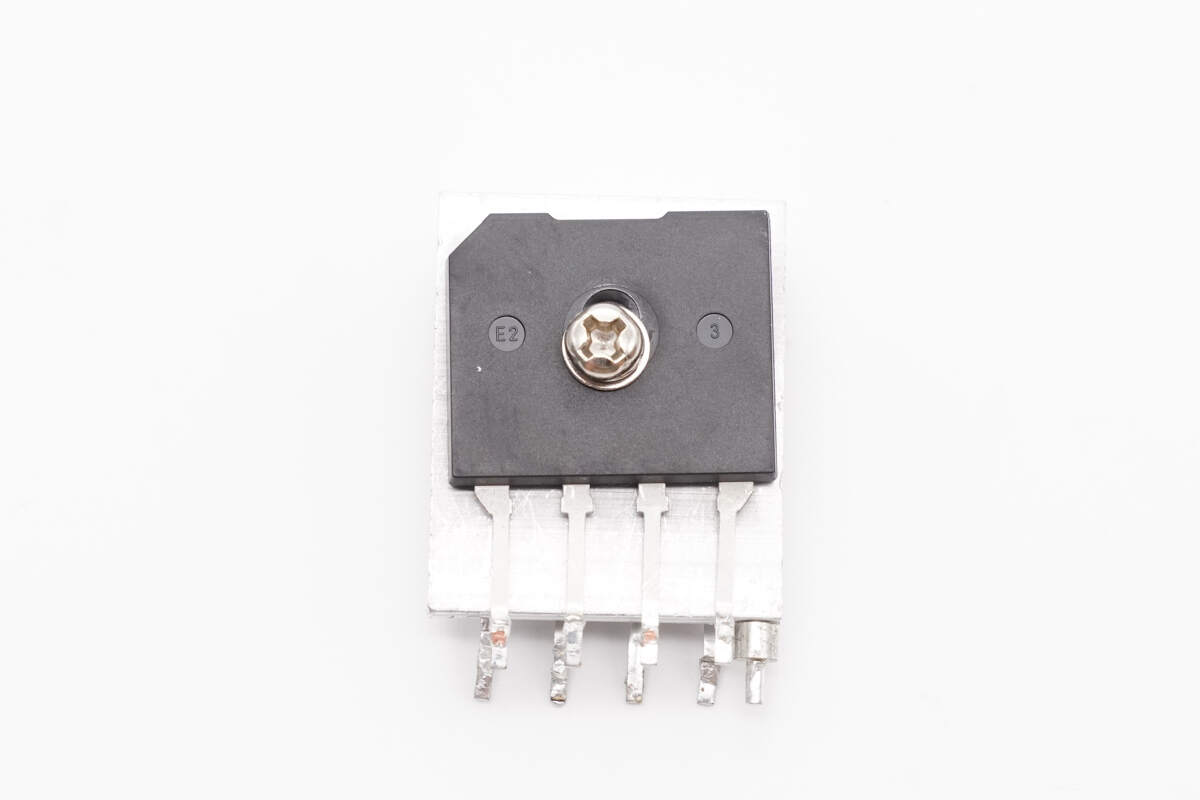
There is a bridge rectifier on each side of the heatsink.
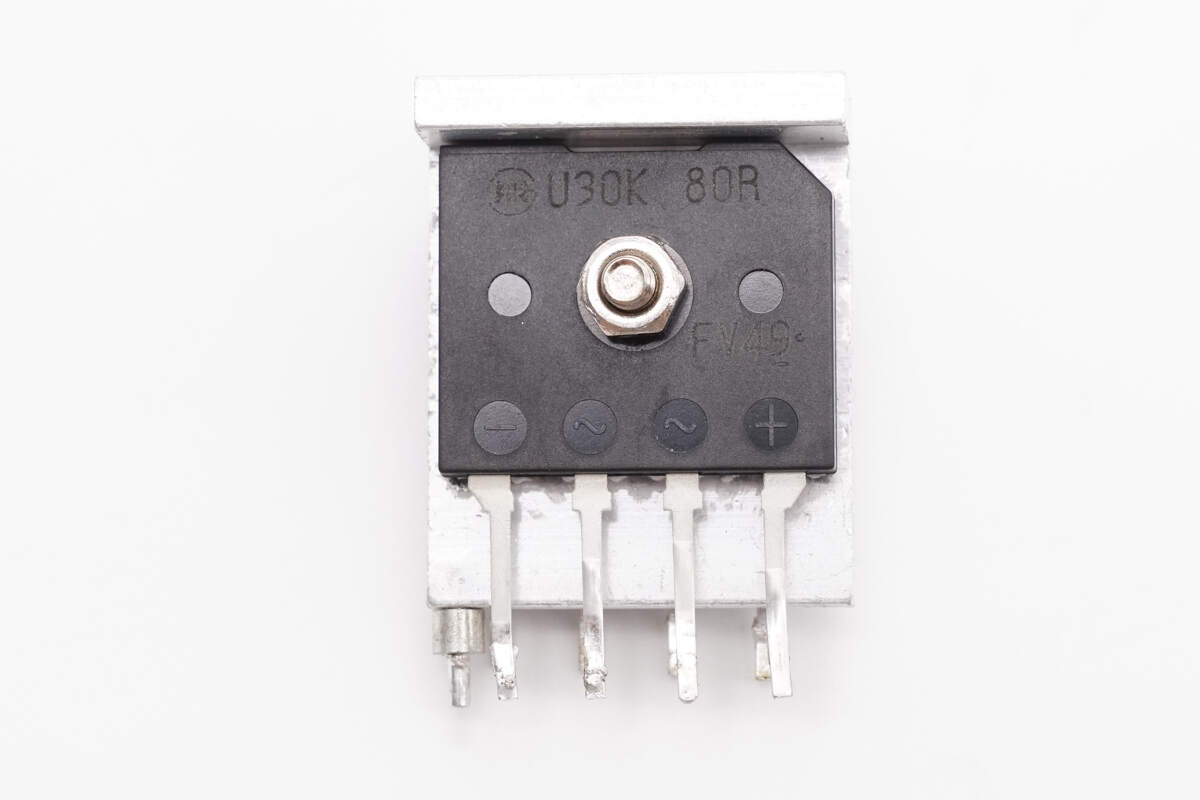
Close-up of the bridge rectifier on the back side.
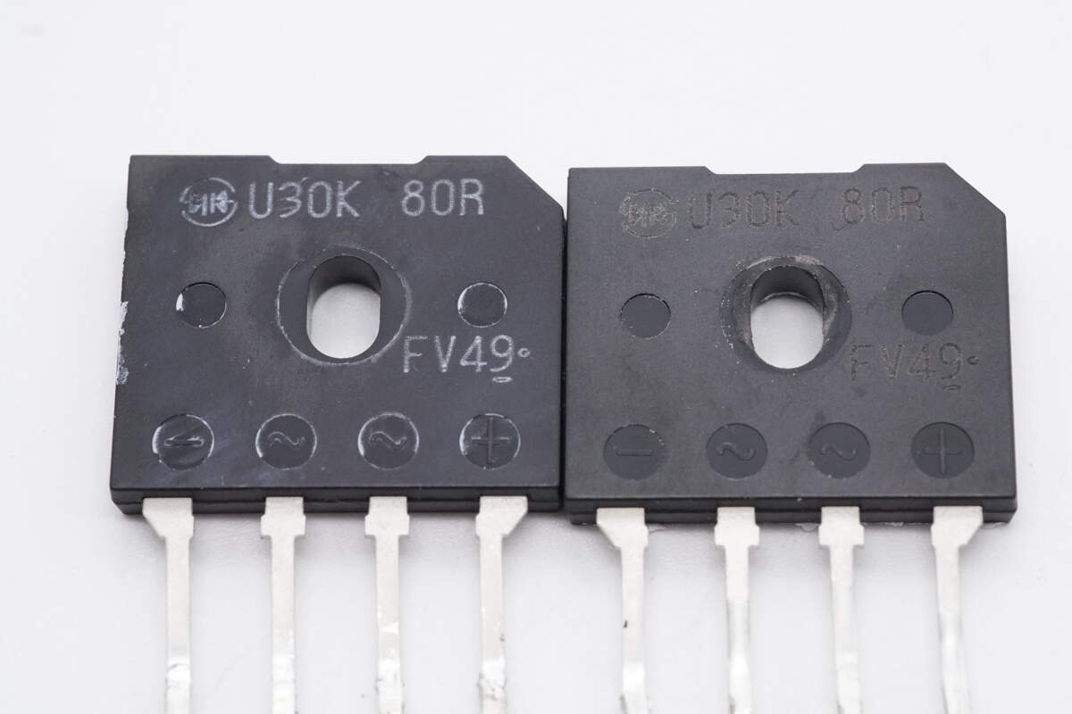
The bridge rectifiers are from Shindengen, model U30K80R, rated at 30A 800V, and use the D6K package.
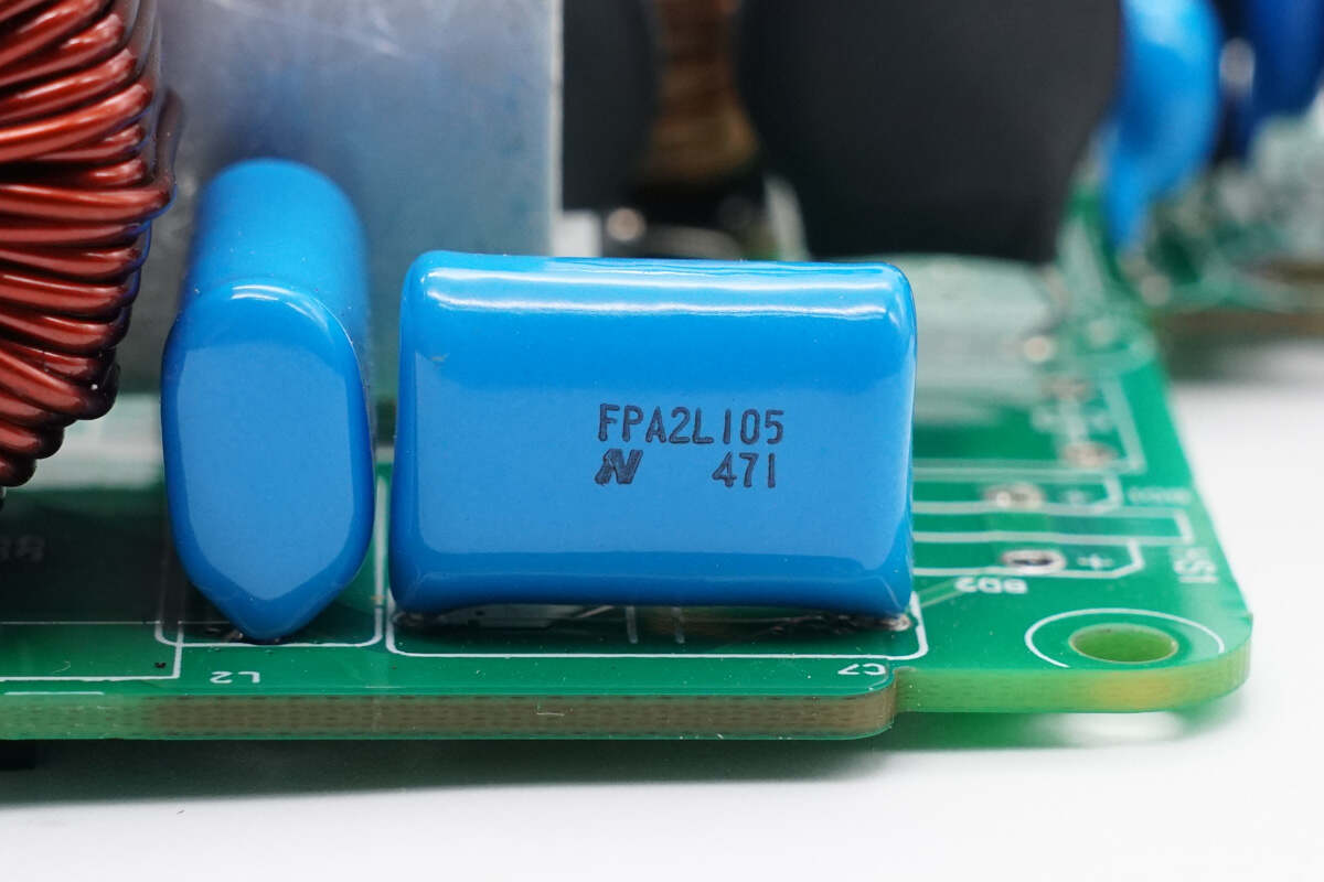
The film capacitor is from Nitsuko, rated at 550V 1μF.
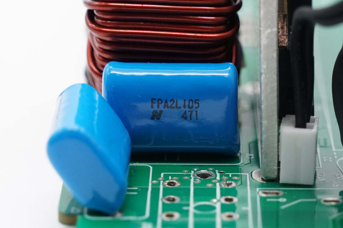
The other film capacitor has the same specifications.
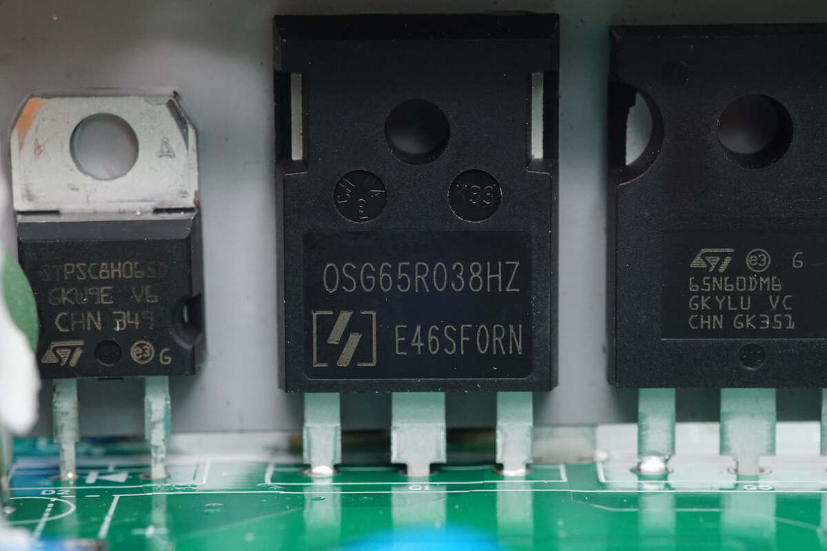
The PFC MOSFET is from Oriental, model OSG65R038HZF. It is an NMOS with a voltage rating of 700V and an on-resistance of 38mΩ, packaged in TO-247.
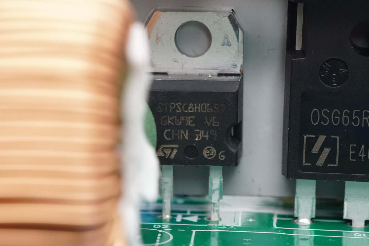
The PFC rectifier is from STMicro, model STPSC8H065D. It is a silicon carbide diode rated at 650V and 8A, packaged in TO-220AC.
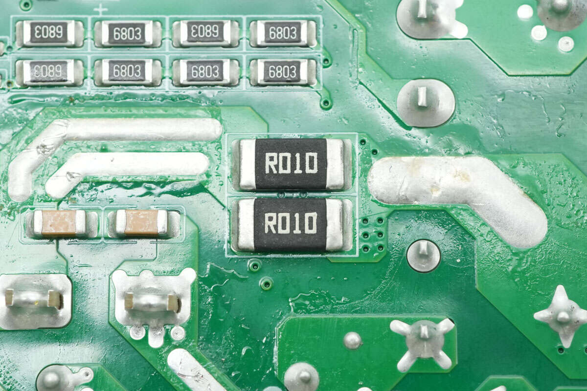
Two 10mΩ sense resistors are used to monitor the MOSFET current.
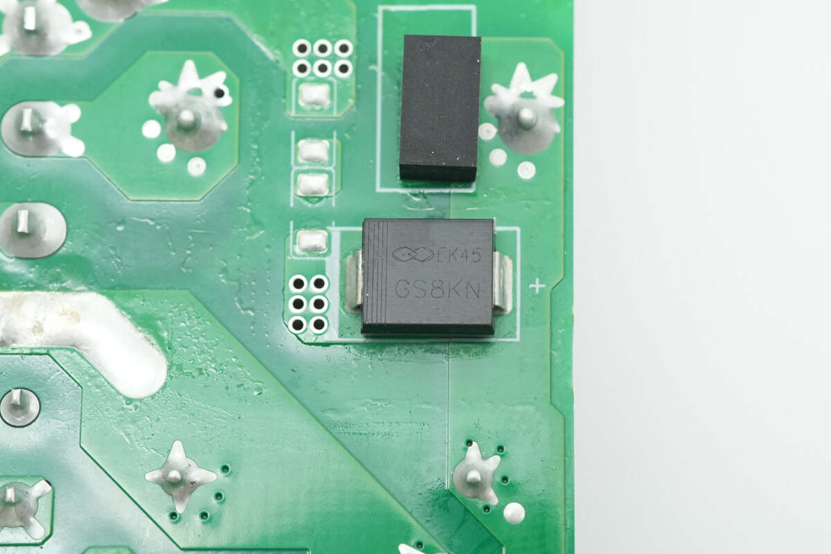
The Gulf Semiconductor GS8KN diode is used for PFC bypass.
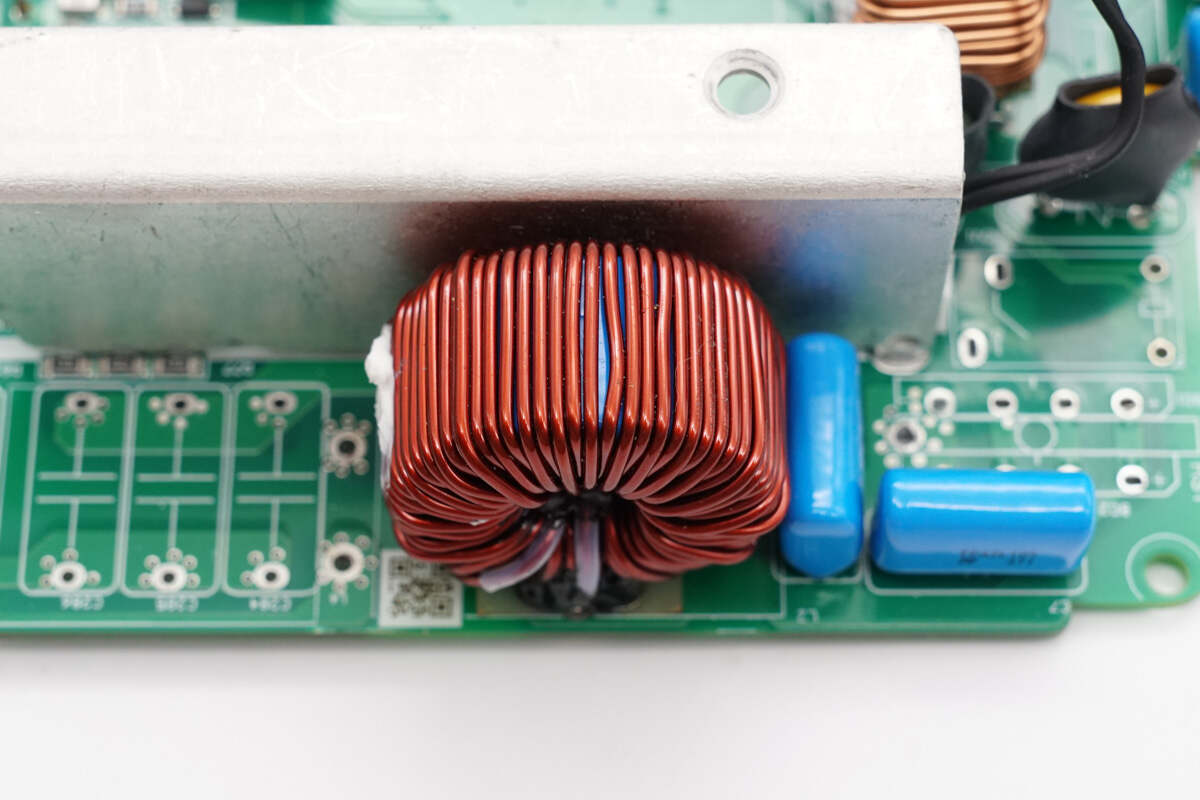
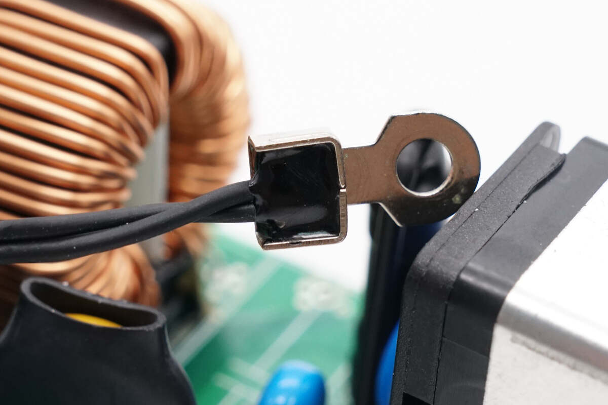
The PFC boost inductor is wound around a magnetic ring and is also insulated with Bakelite.
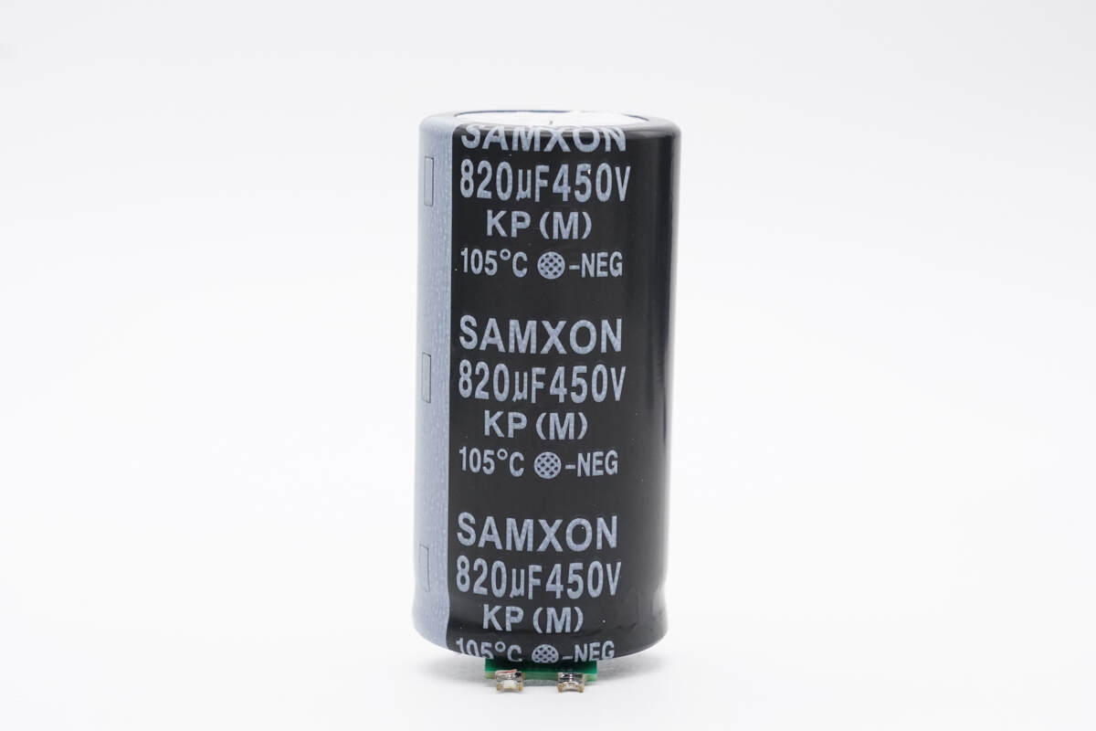
The high-voltage filter capacitor is from SAMXON, rated at 820μF 450V.
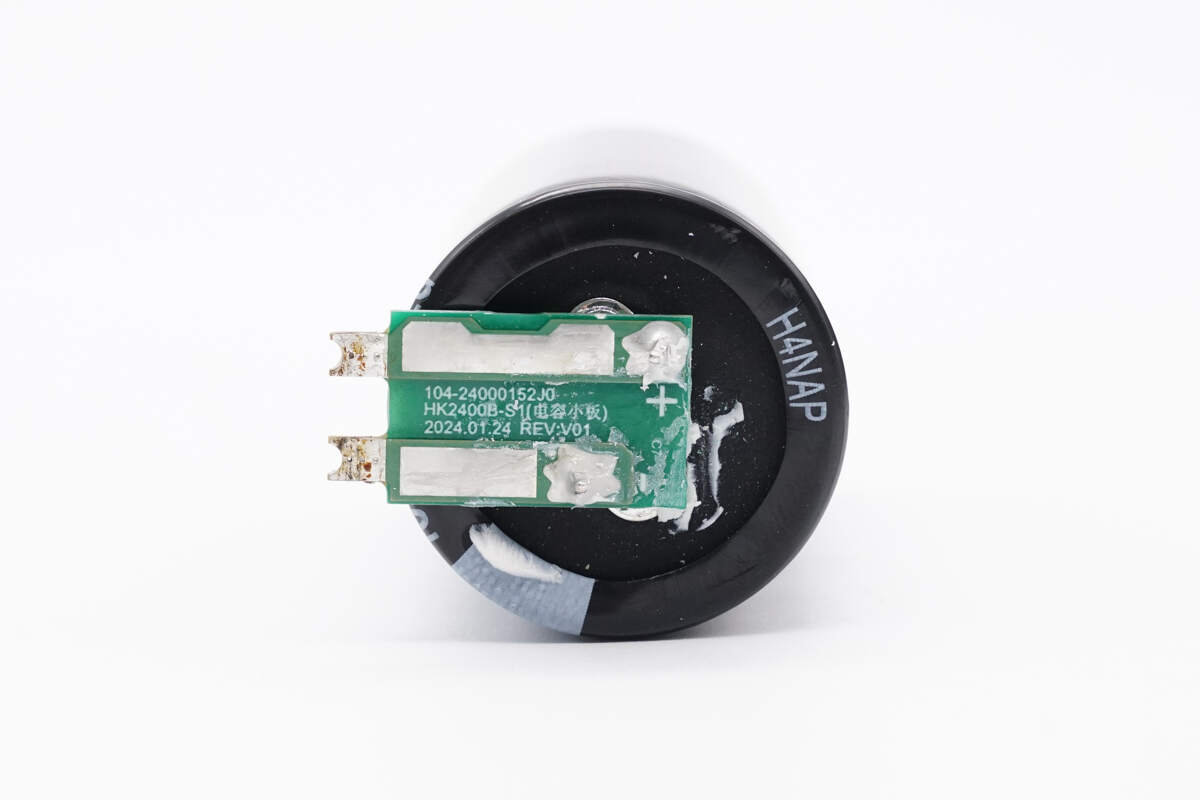
The capacitor is connected via a small PCB adapter.
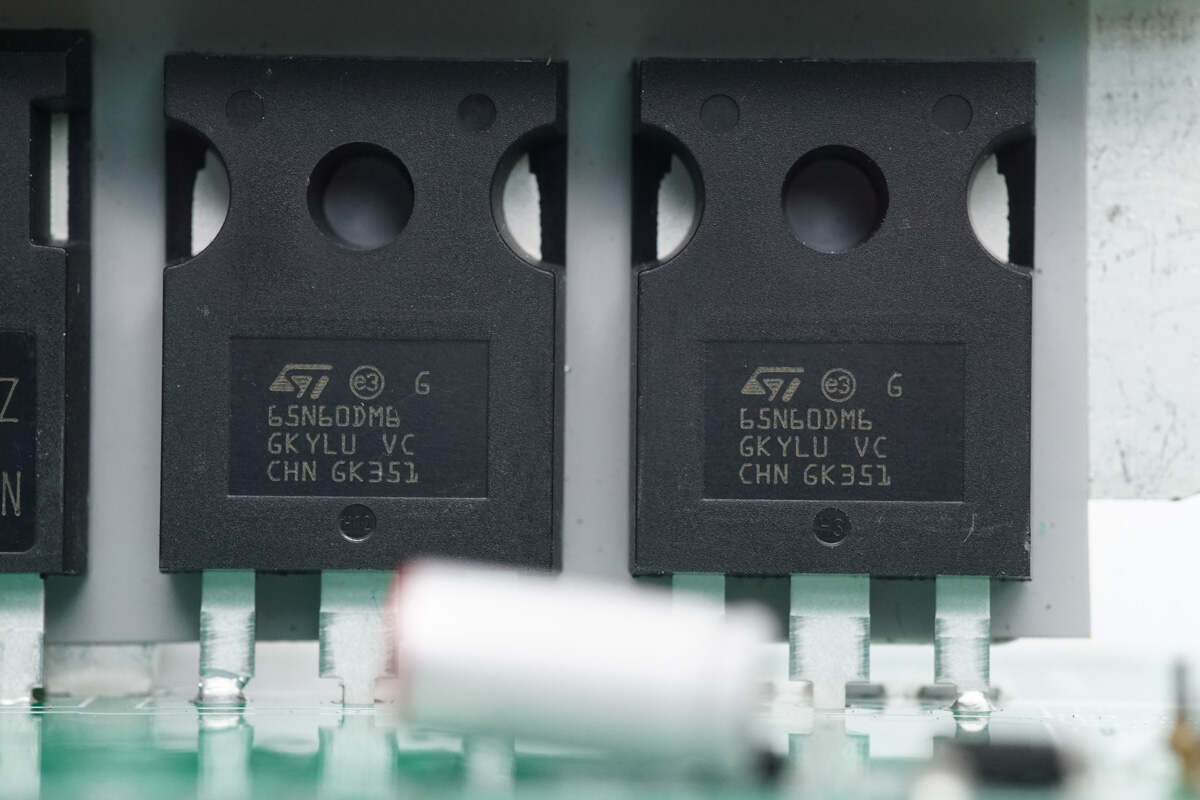
Two LLC MOSFETs are from STMicro, model STW65N60DM6. They are NMOS devices rated at 600V with an on-resistance of 60mΩ, packaged in TO-247.
A thermistor is mounted on the heatsink for temperature sensing.
The core of the resonant inductor is tightly wrapped with high-temperature insulating tape.
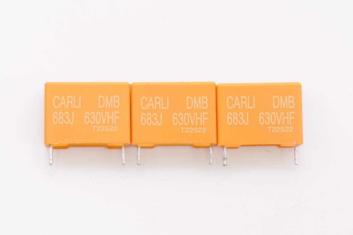
The resonant capacitors are from Carli, each rated at 0.068μF 630V, connected in parallel with three units.
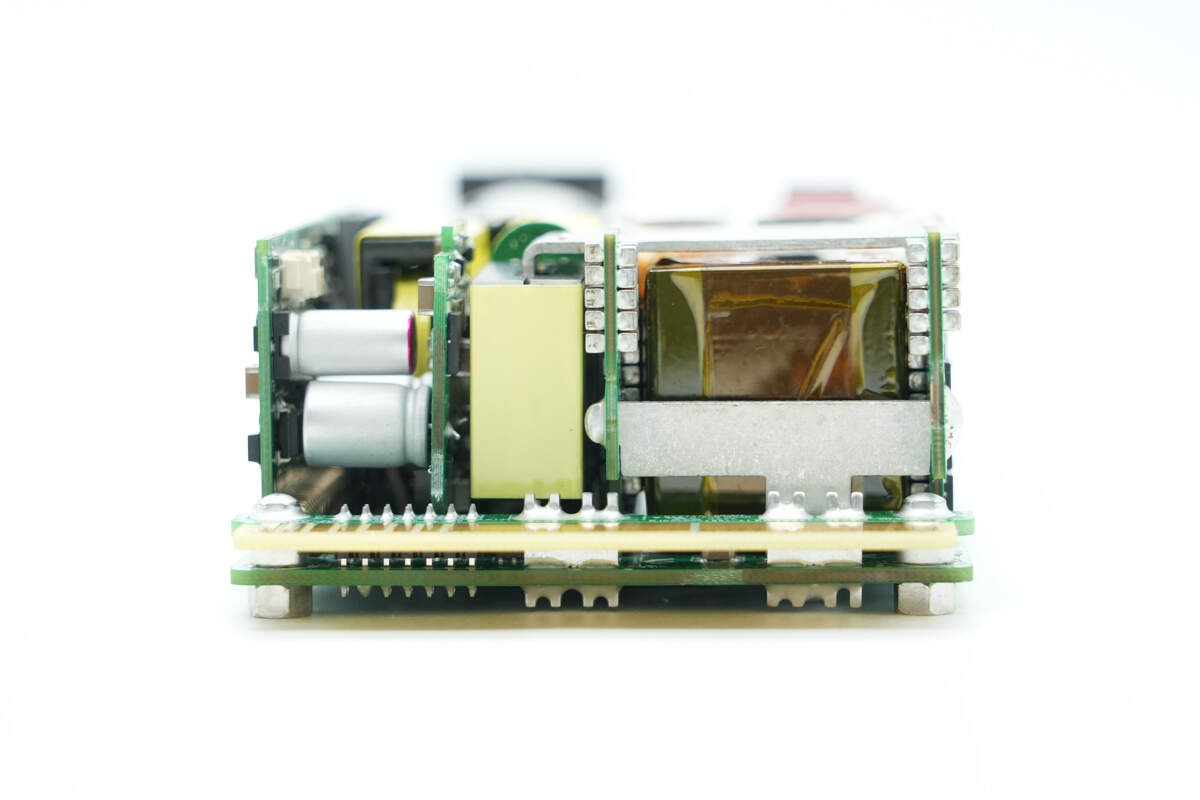
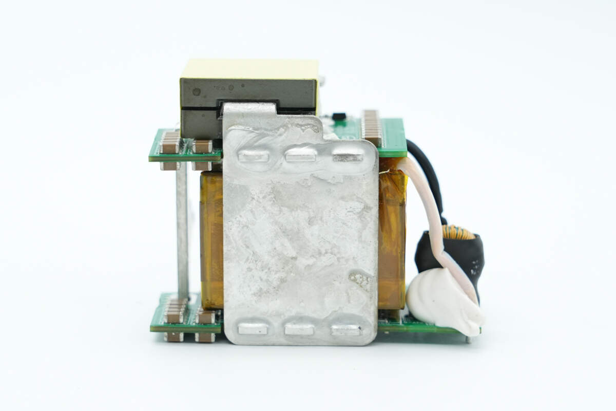
The output side includes a transformer, a filter inductor, and a rectification PCB.
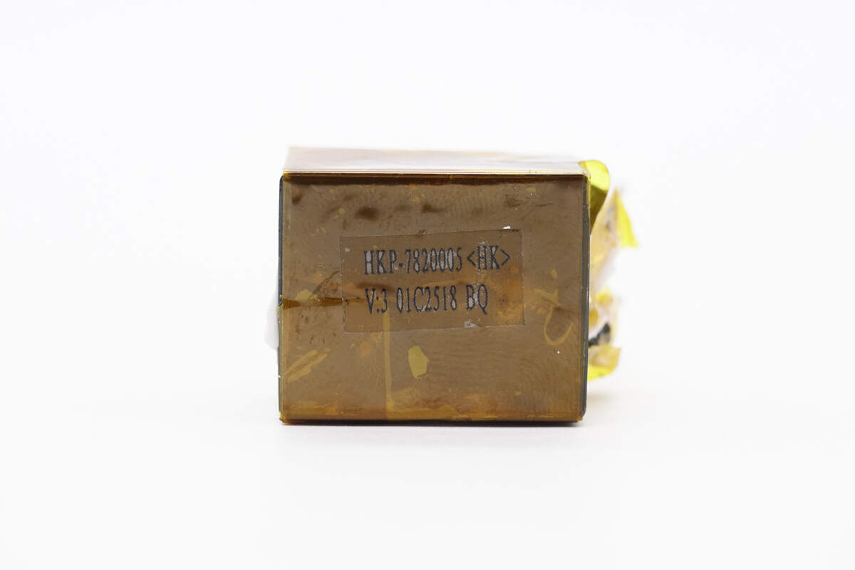
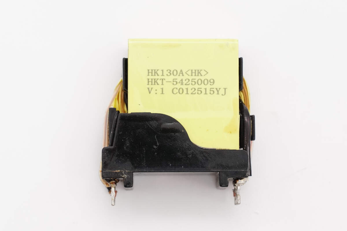
The transformer module is composed of the transformer and PCBs.
There is a filter inductor on the other side.
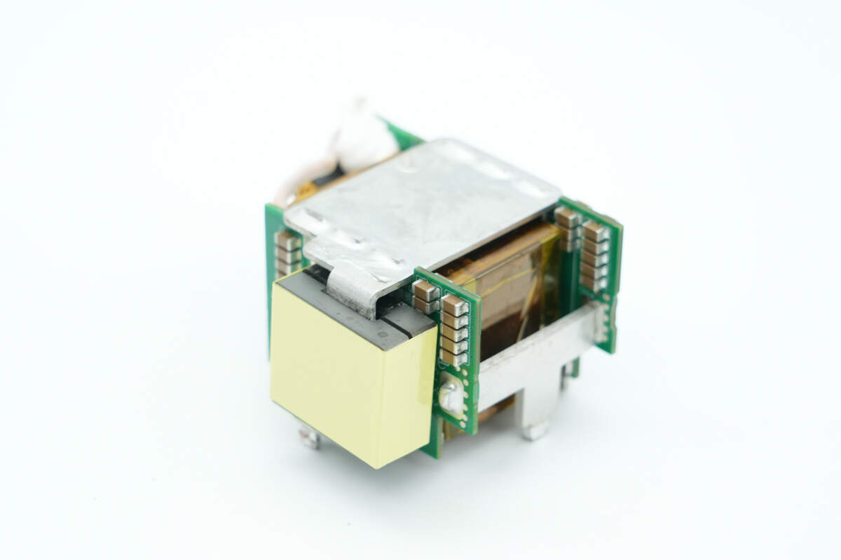
The two PCBs are connected by a copper plate.
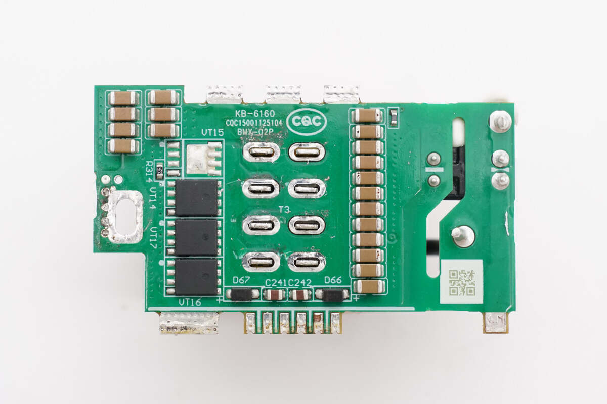
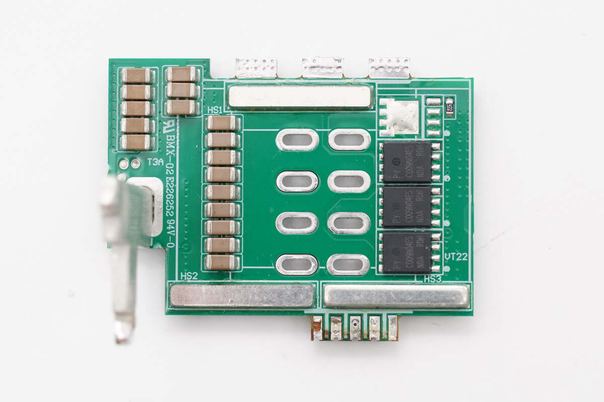
After removing the copper plate, the side PCB has synchronous rectifiers and filter capacitors.
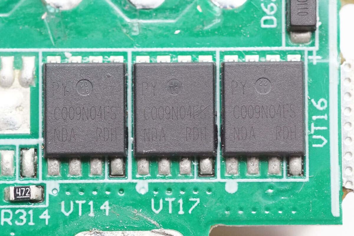
The synchronous rectifiers are from Pingwei, marked with PWC009N04ES, and come in a DFN 5×6 package.
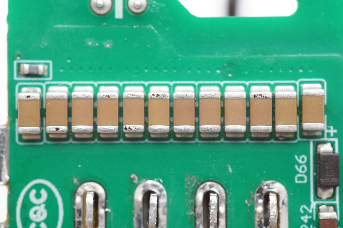
Close-up of the parallel MLCC filter capacitors.
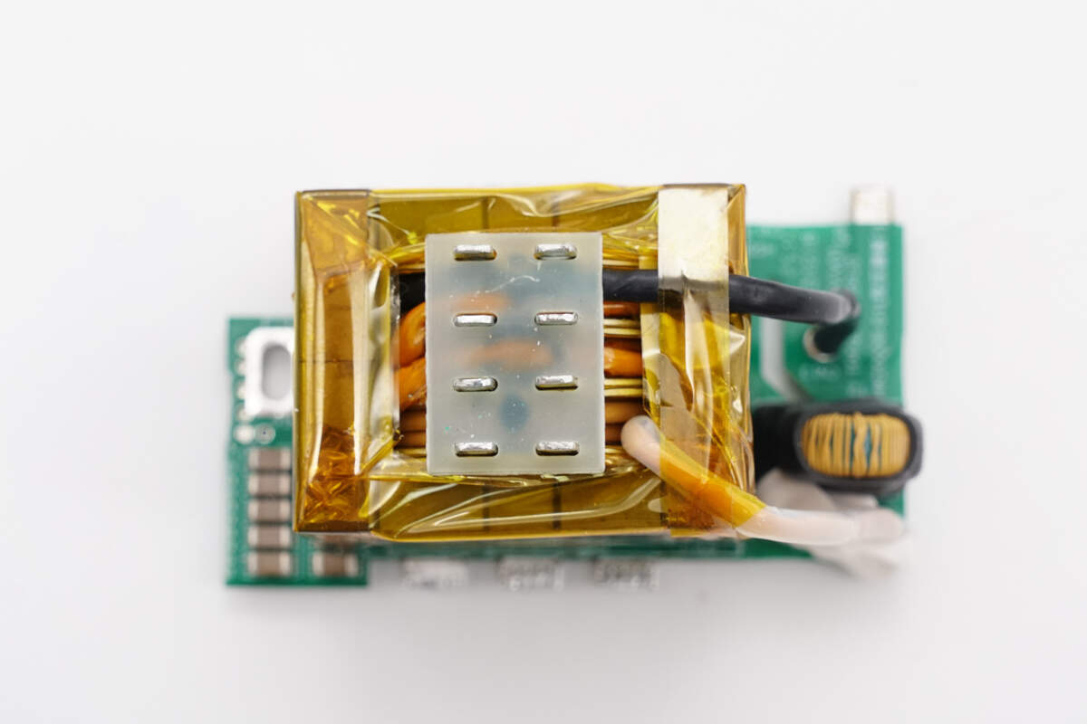
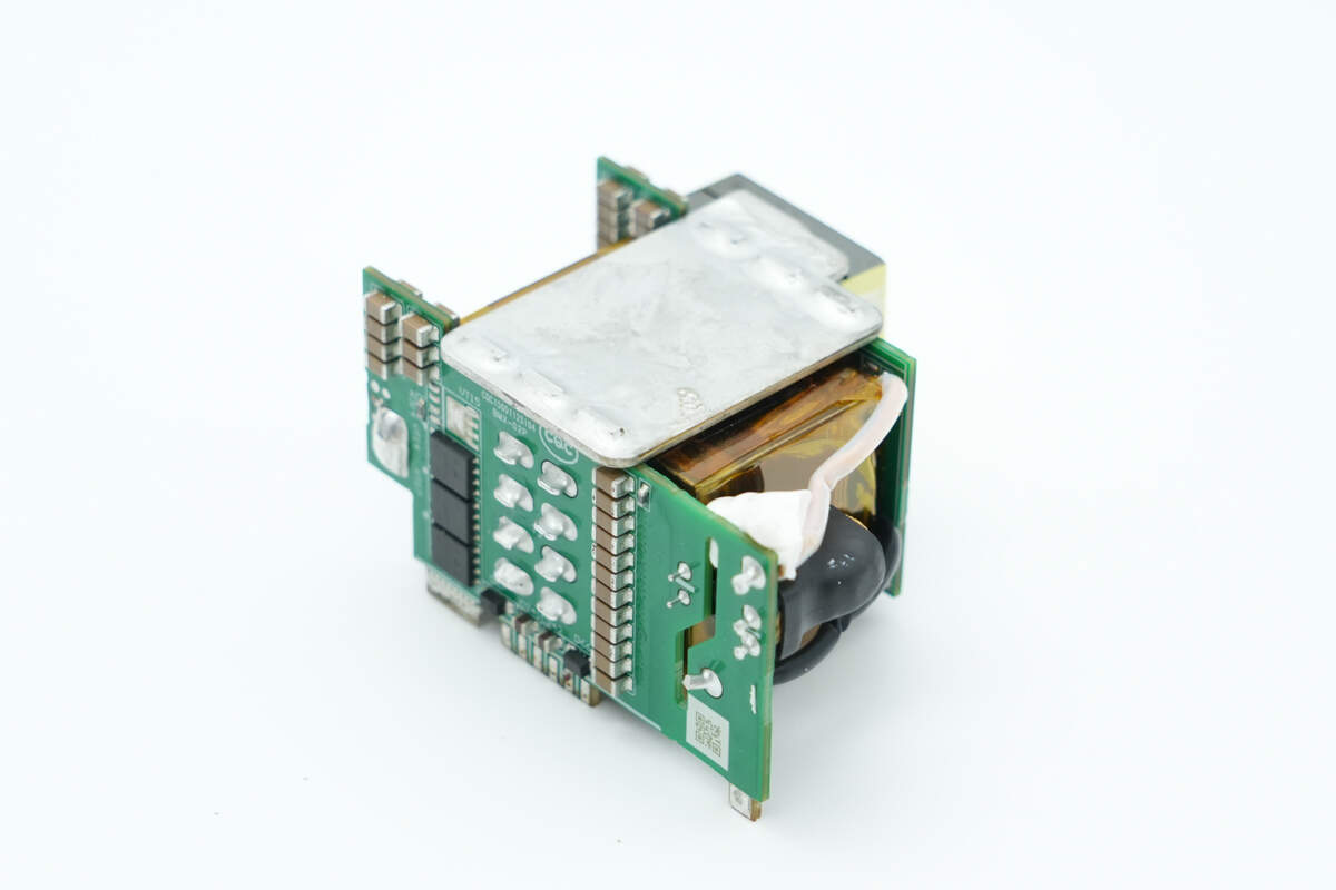
The transformer primary winding uses Litz wire, while the secondary winding is connected with soldered copper strips.
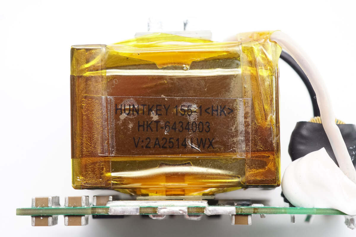
The transformer core is tightly wrapped with insulating tape.
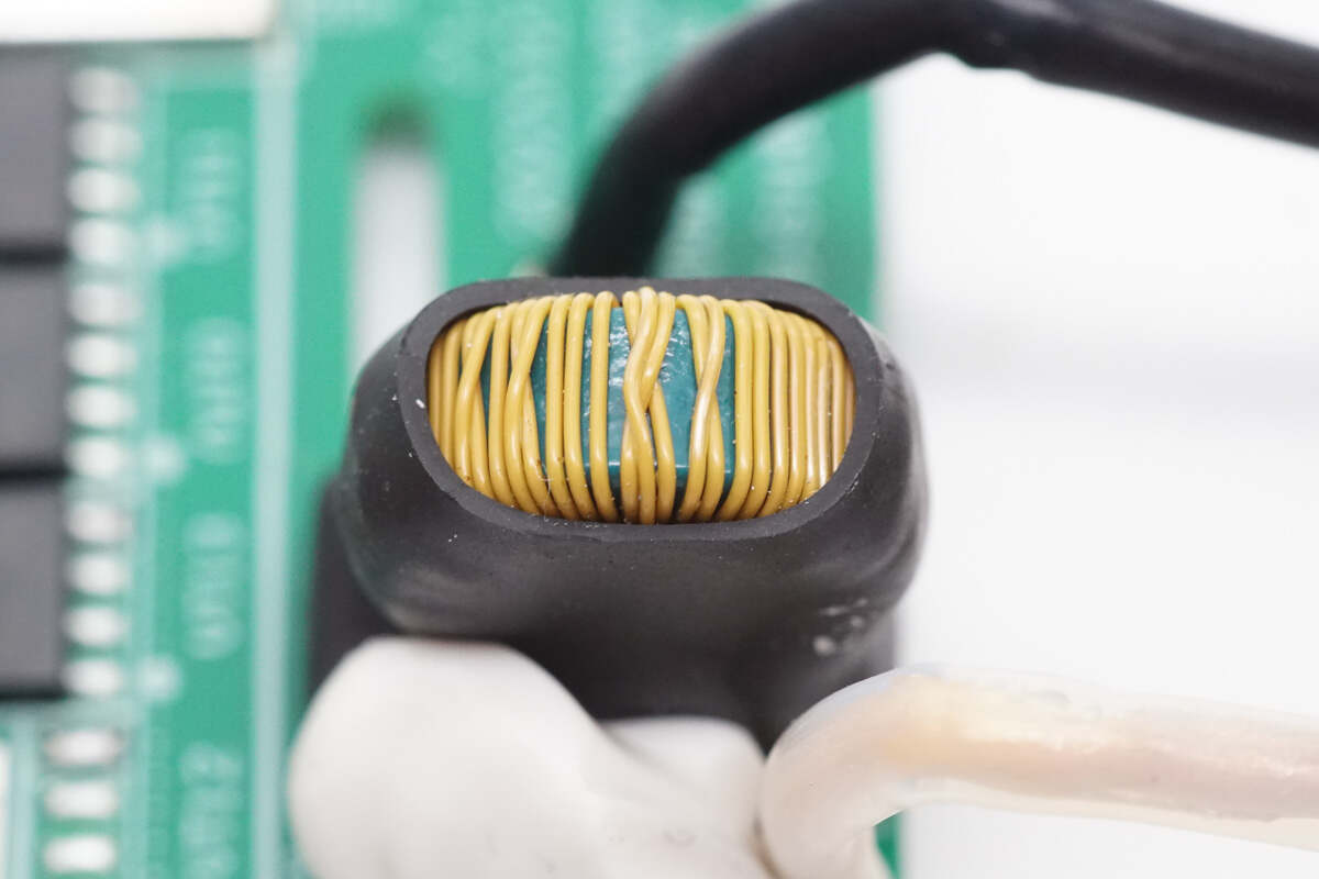
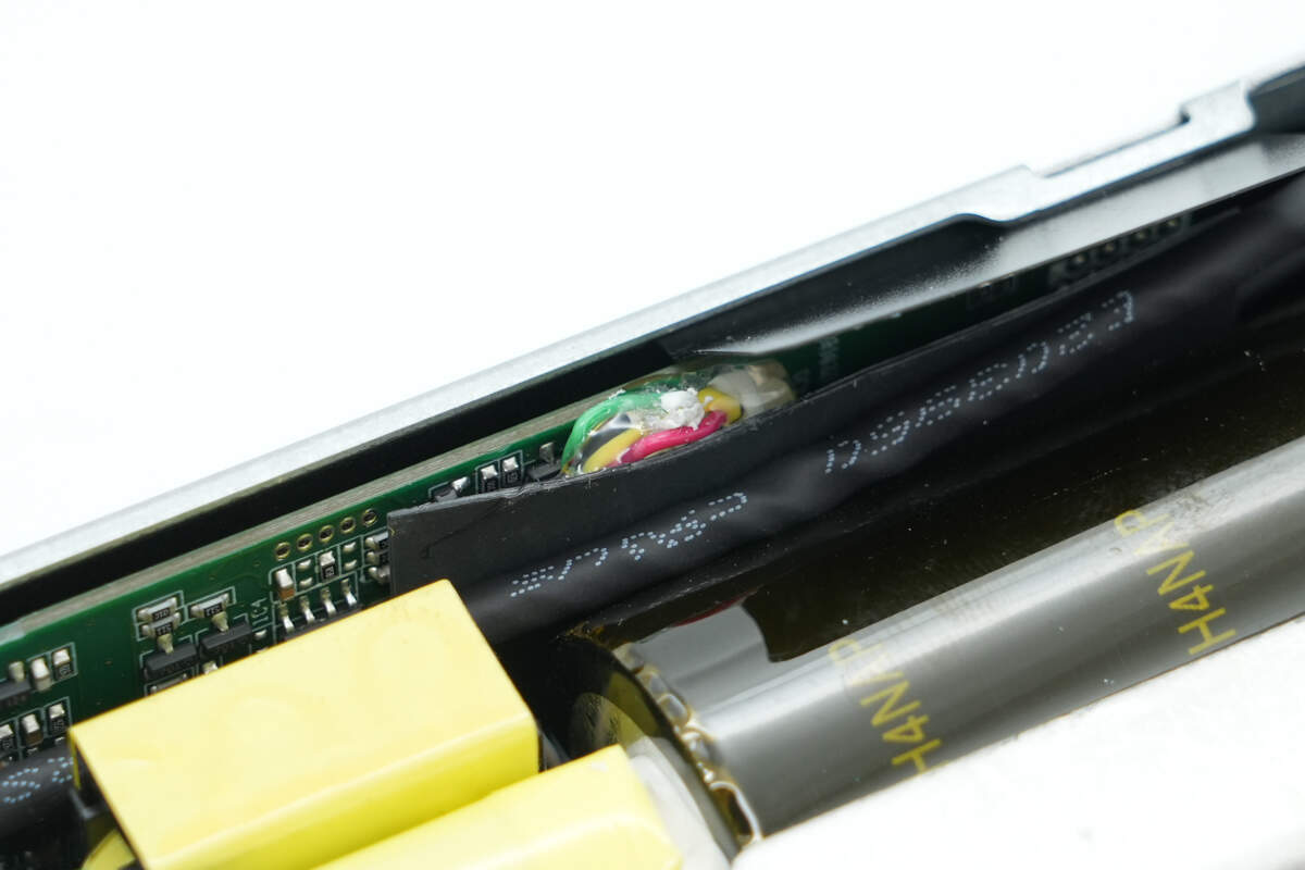
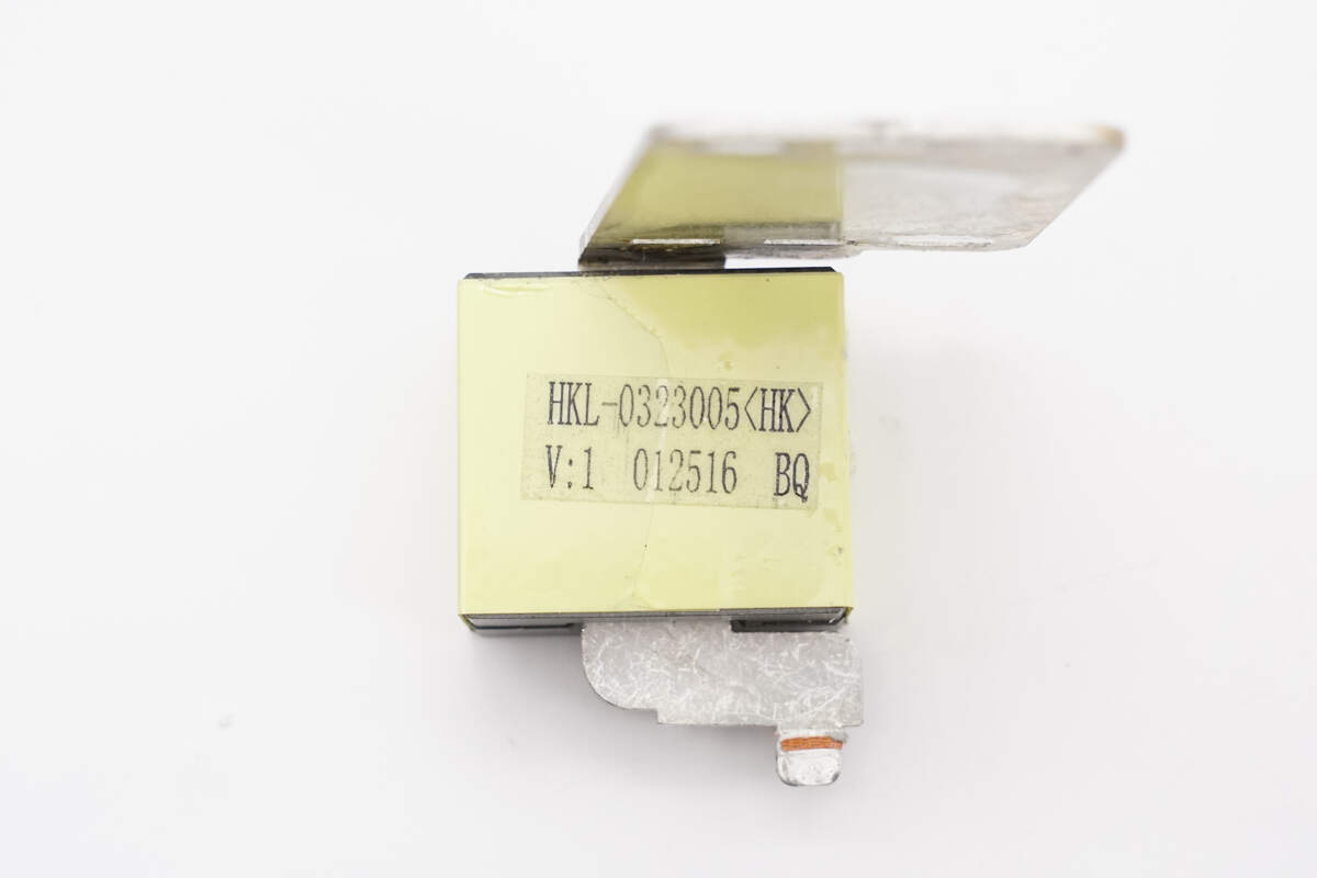
The current transformer used to detect the primary coil current of the transformer is insulated with heat-shrink tubing.
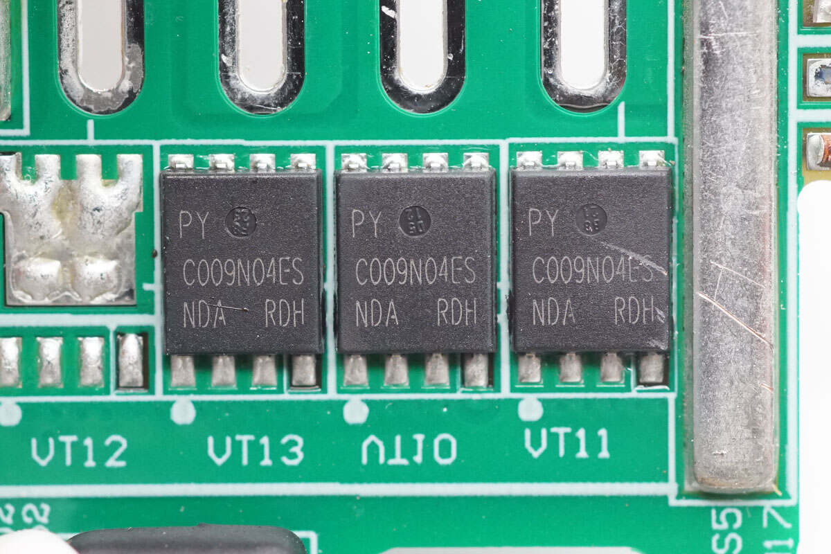
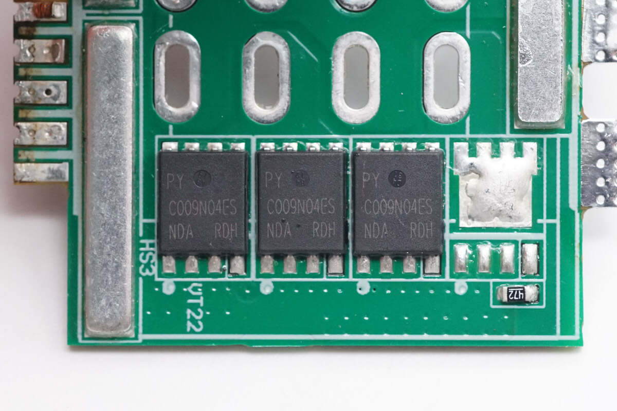
Below the transformer, there are three synchronous rectifiers of the same model.
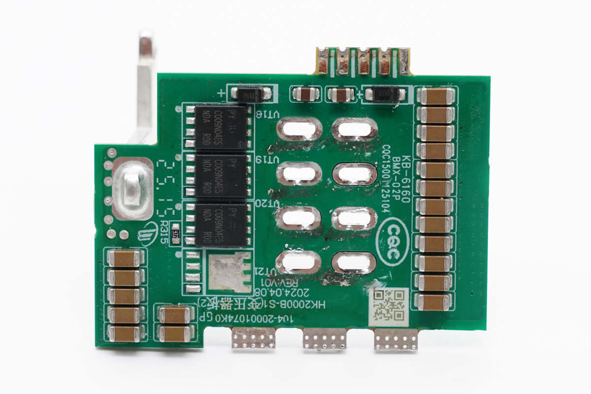
The other PCB has synchronous rectifiers and MLCC capacitors.
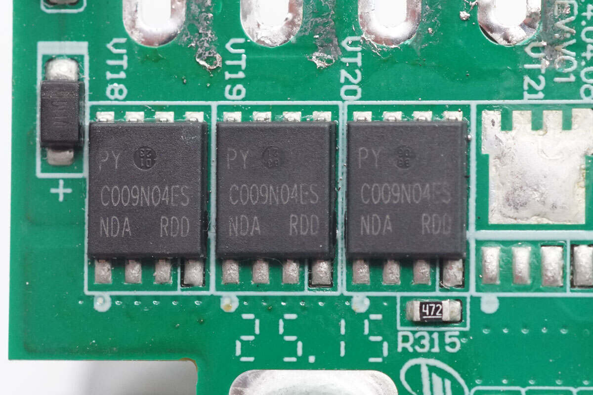
The synchronous rectifiers are also Pingwei PWC009N04ES.
The other side features filter capacitors and synchronous rectifiers, with copper bars soldered for current sharing.
Below the transformer, there are three synchronous rectifiers of the same model.
One end of the filter inductor is connected to the PCB.
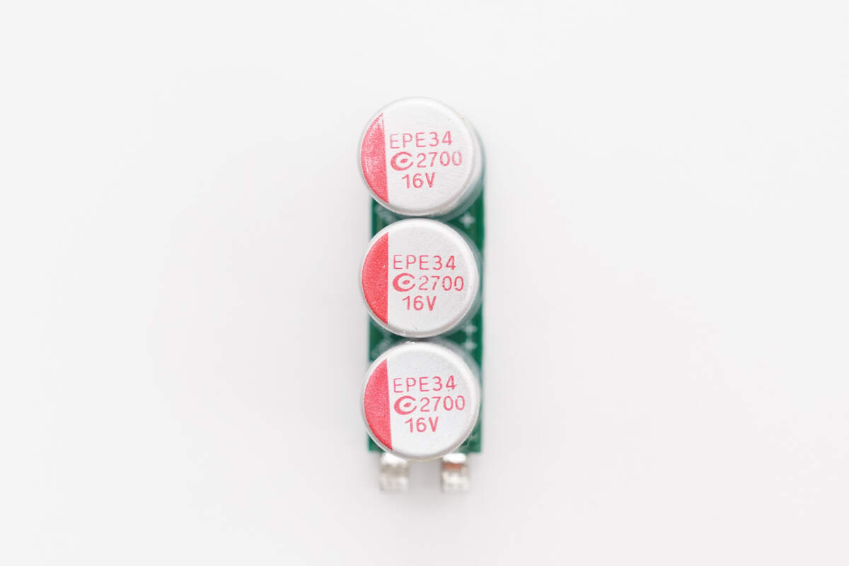
The output filter capacitors are soldered onto a vertical PCB. They are from APAQ, rated at 2700μF 16V, and connected in parallel with three units.
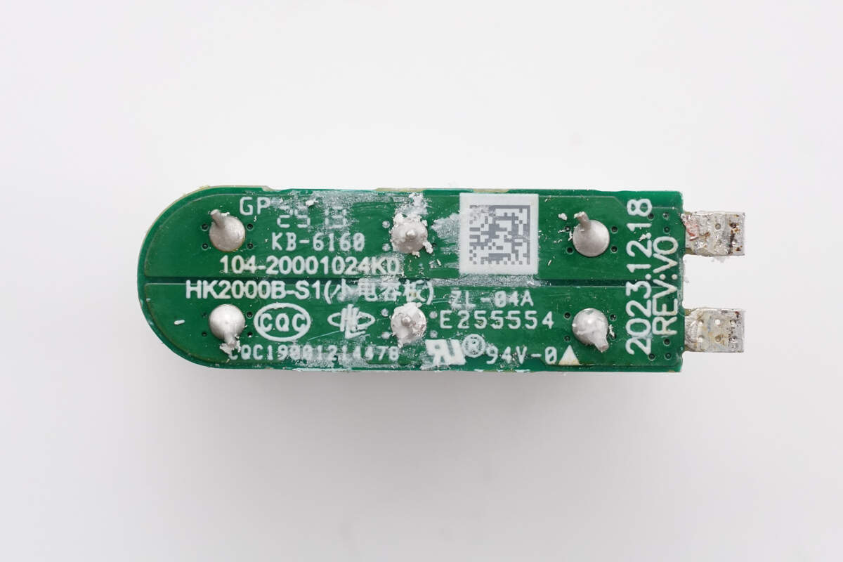
The back side of the vertical PCB has no components.
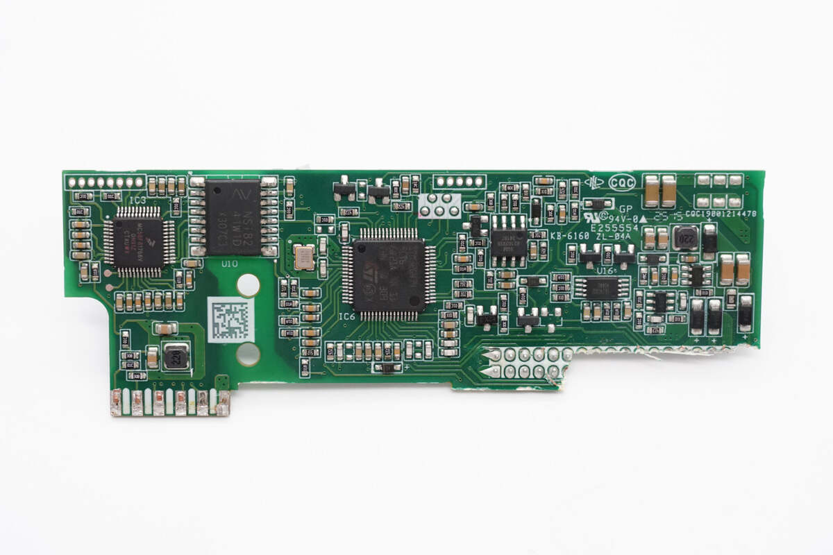
On the left side of the control PCB is the PFC controller, which communicates with the master control chip through an isolation chip. The right side houses operational amplifiers and memory.
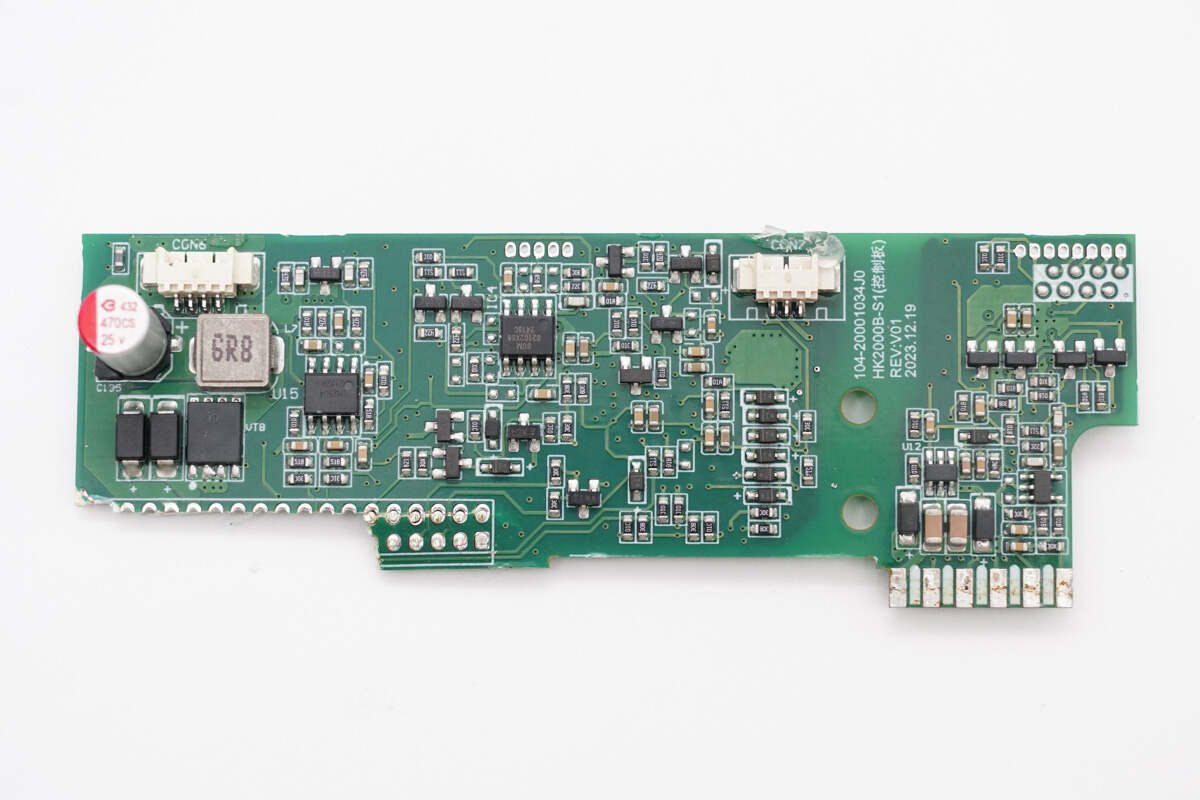
The other side features a filter capacitor, a filter inductor, and operational amplifiers.
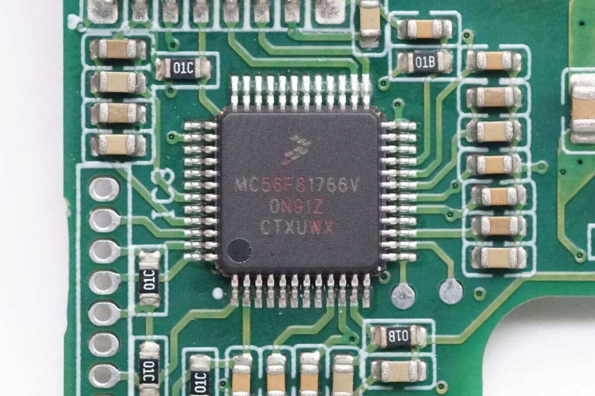
The PFC controller is from NXP, model MC56F81766V. It is a digital signal controller featuring a high-performance 56800EX core running up to 100 MHz, with 128KB of internal FLASH and 20KB of RAM. It comes in a 48-pin LQFP package.
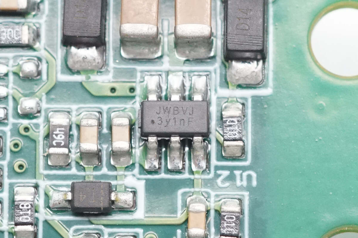
The synchronous buck chip is from JOULWATT, marked with JWBV, model JW5017S. It is a synchronous buck converter with a 26V input voltage, 1.2A output current, and a switching frequency of 1.2MHz. It features input undervoltage lockout, startup overcurrent protection, output overcurrent protection, and thermal shutdown. The chip comes in an SOT23-6 package.
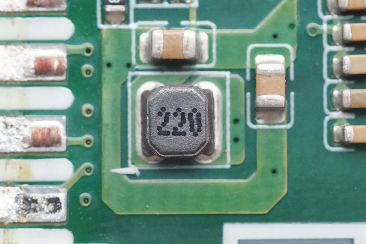
Close-up of the 22μH buck inductor.
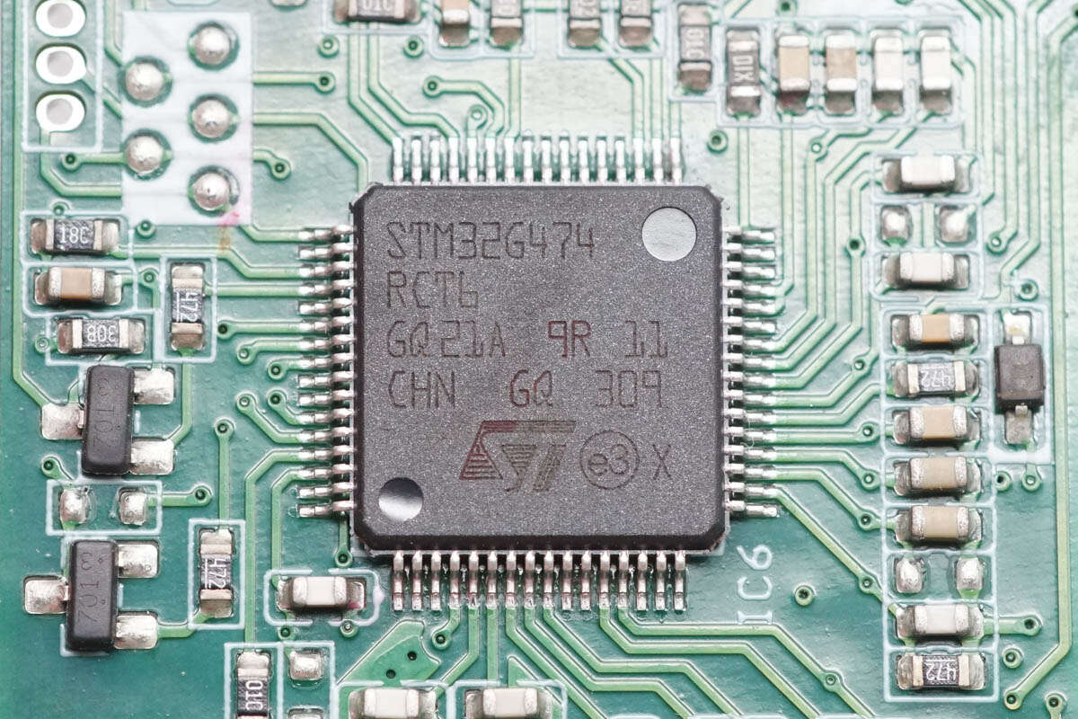
The master control chip is from STMicro, model STM32G474RCT6. It features an ARM Cortex-M4 MCU running at 170MHz, with an integrated FPU and DSP. It includes 256KB of FLASH and 128KB of SRAM, supports standard and advanced communication interfaces, and comes in an LQFP64 package.
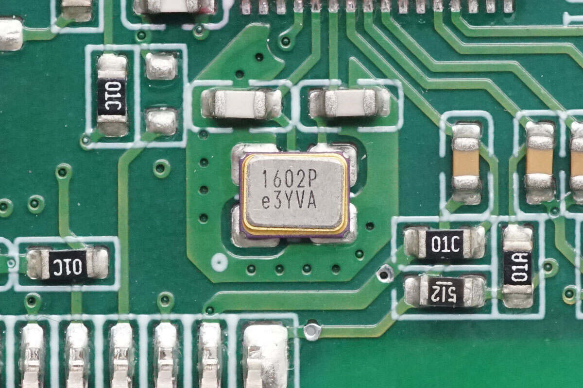
Close-up of the external SMD clock crystal oscillator.
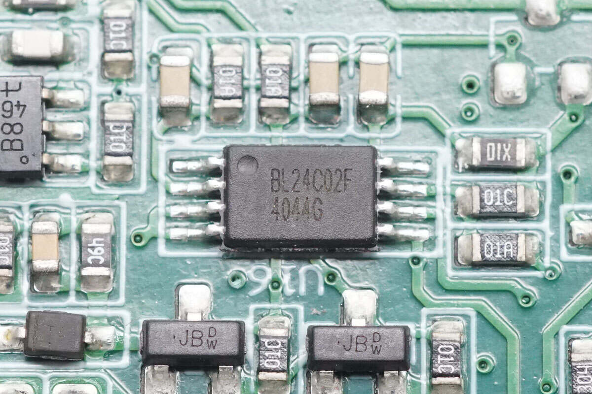
The memory chip is from Belling, model BL24C02F, with a capacity of 2KB, packaged in TSSOP8L.
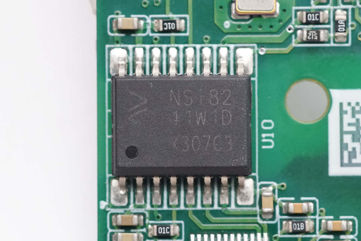
The isolation communication chip is from NOVOSENSE, model NSi8241W1D. It is a bidirectional four-channel digital isolator supporting a data rate of 150 Mbps, housed in a SOP16 package.
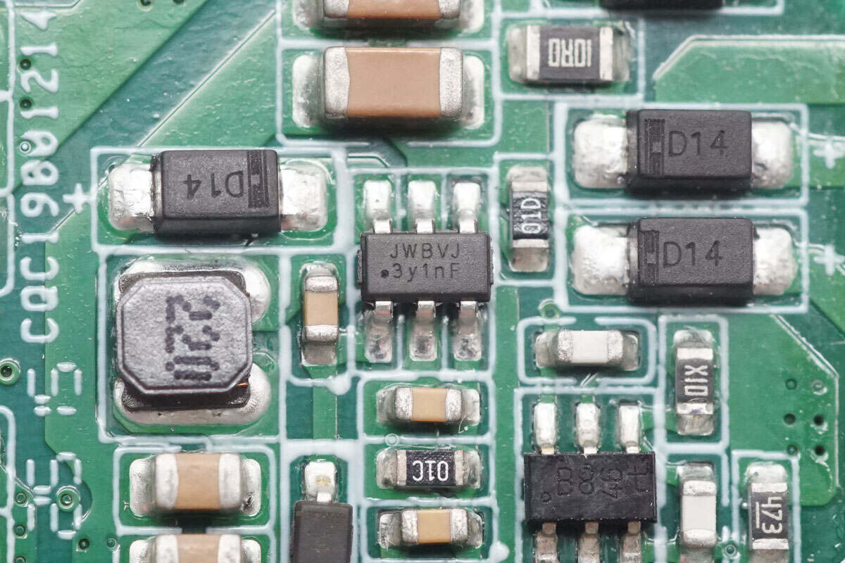
The JOULWATT JW5017S synchronous buck chip supplies power to the master control chip.
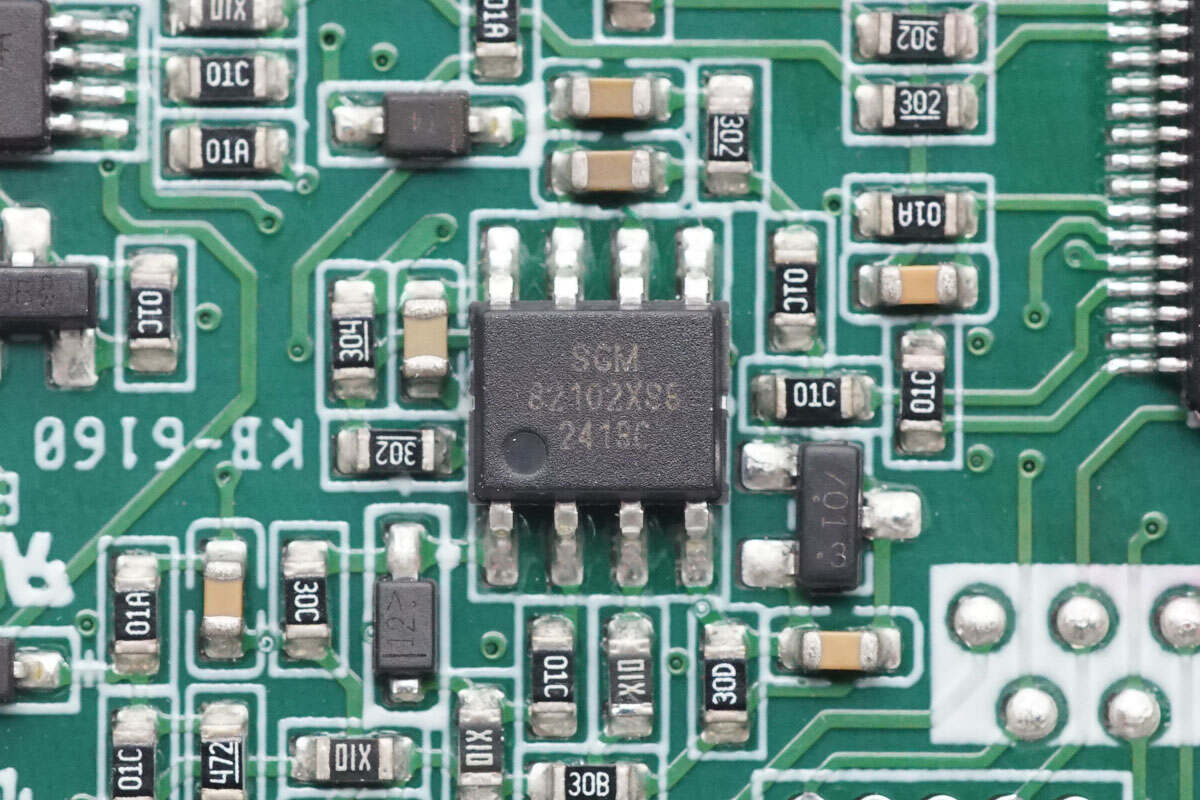
The dual operational amplifier is from SGMICRO, model SGM8210-2. It is a low-power, low-noise, rail-to-rail dual op-amp, packaged in SOIC-8.
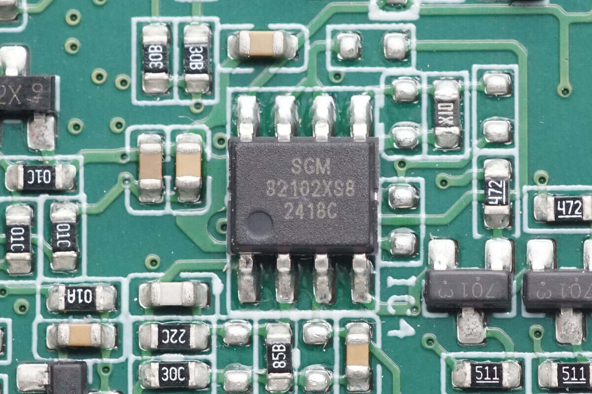
The other operational amplifier has the same specifications.
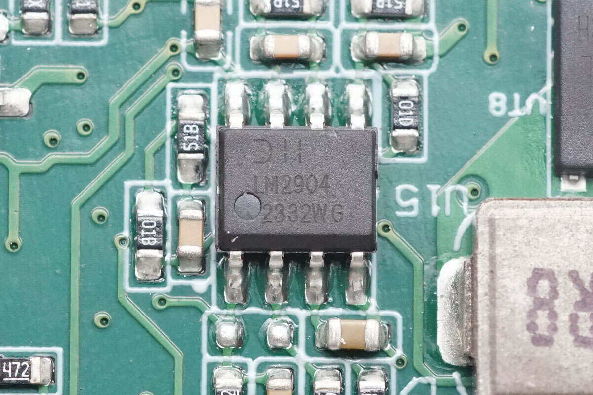
The dual operational amplifier is from DIODES, model LM2904, packaged in SO-8.
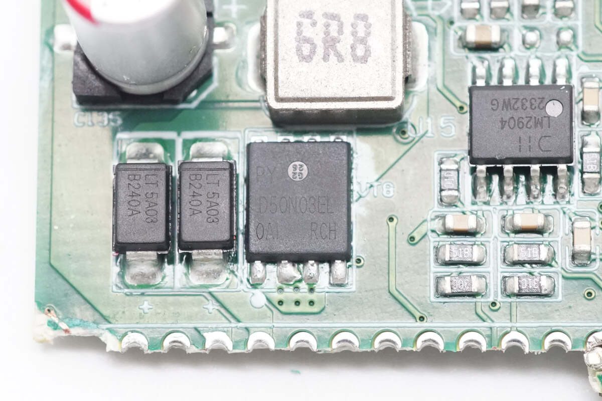
The MOSFET is from Pingwei, model D50N03EL. It is an NMOS with a voltage rating of 30V and an on-resistance of 6mΩ, packaged in DFN 5×6.
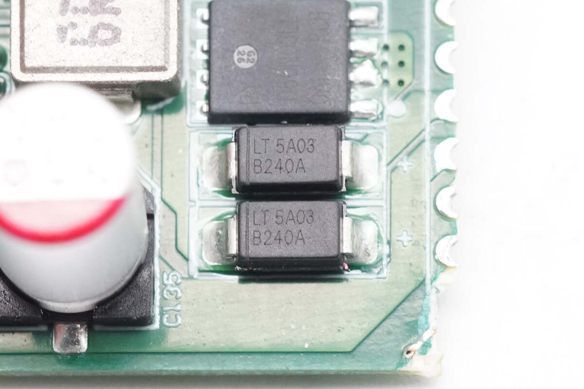
Two diodes are from LITEON, model B240A, rated at 40V 2A, and come in SMA packages.
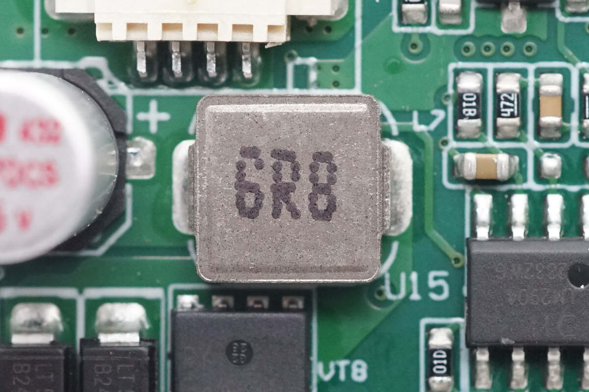
Close-up of the 6.8μH alloy inductor.
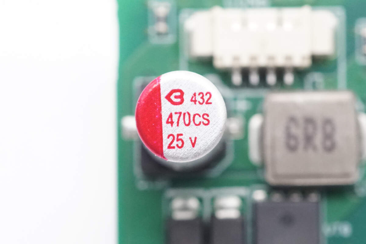
The filter capacitor is from BERYL, part of the CS series of SMD solid capacitors, rated at 470μF 25V.
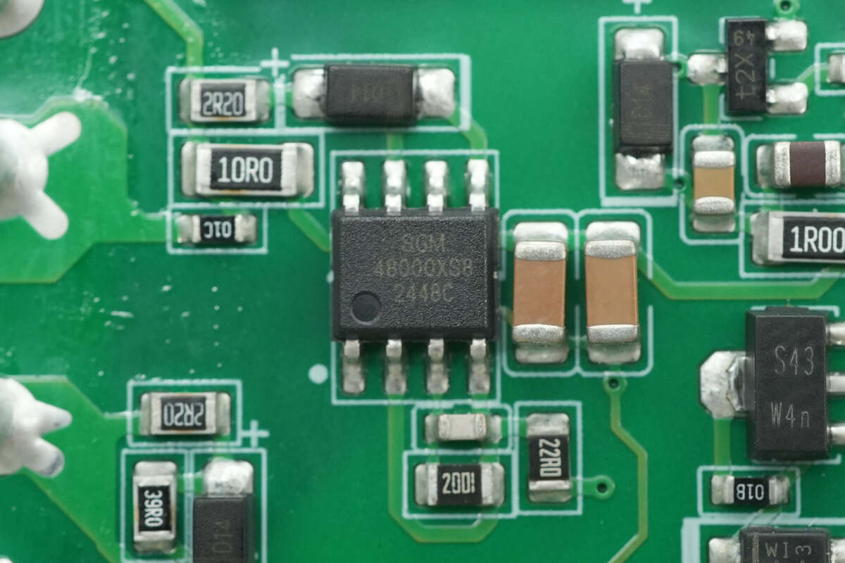
The PFC MOSFET driver is from SGMICRO, model SGM48000. It is a high-speed dual low-side driver with a 2A current capability, packaged in SOIC-8.
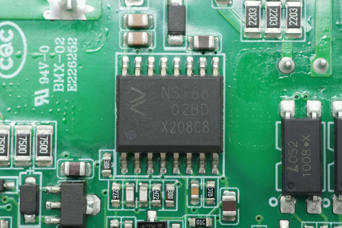
The LLC MOSFET driver is from NOVOSENSE, model NSi6602BD. It features an integrated isolated dual-channel gate driver with 4A source current and 6A sink current capabilities, packaged in SOW16.
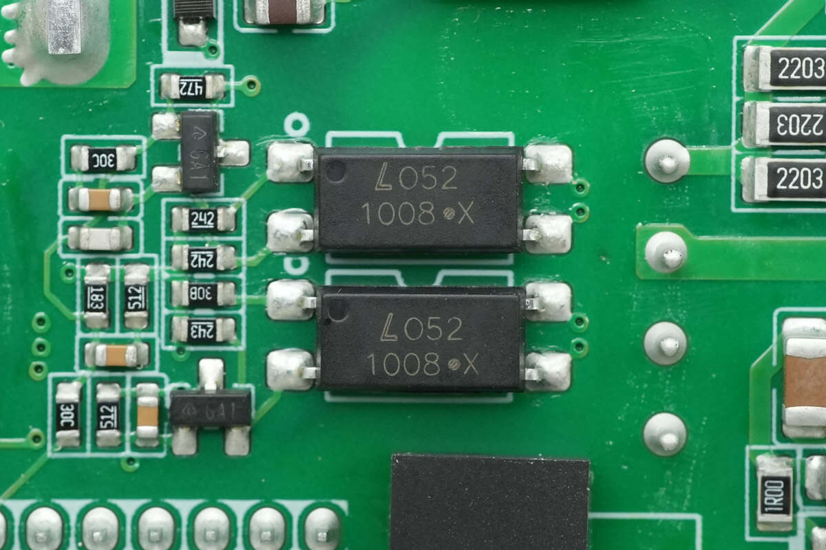
Two LITEON LTV-1008 optocouplers are used for isolated communication between the primary and secondary sides.
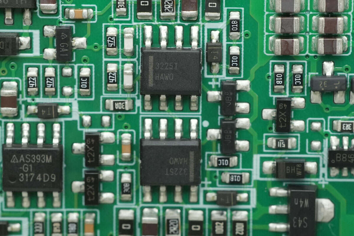
The synchronous rectifier driver is from Onsemi, model FAN3225T. It is a high-speed dual low-side driver with a 4A current capability, packaged in SOIC-8.
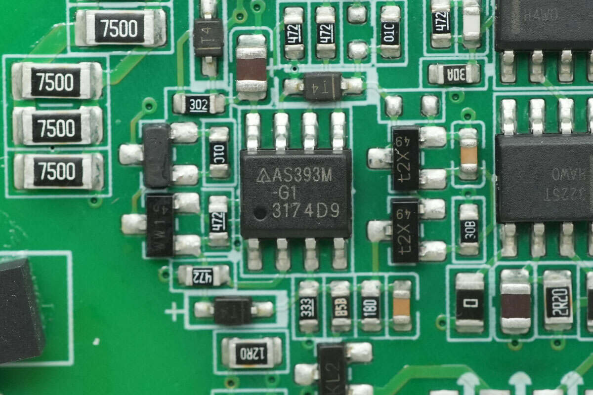
Close-up of the DIODES AS393M dual voltage comparator.
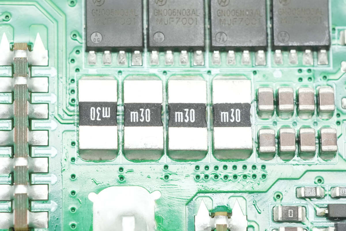
Four 0.3mΩ sense resistors are connected in parallel to monitor the output current.
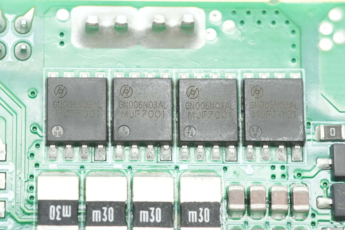
The MOSFET used for output power control is from Hunteck, model HGN006N03AL. It is an NMOS with a voltage rating of 30V and an on-resistance of 0.55mΩ, packaged in DFN 5×6.
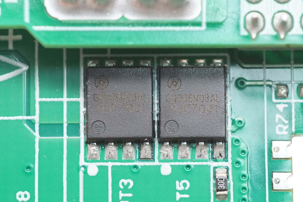
On the other side, there are two additional MOSFETs of the same model, making a total of six connected in parallel.
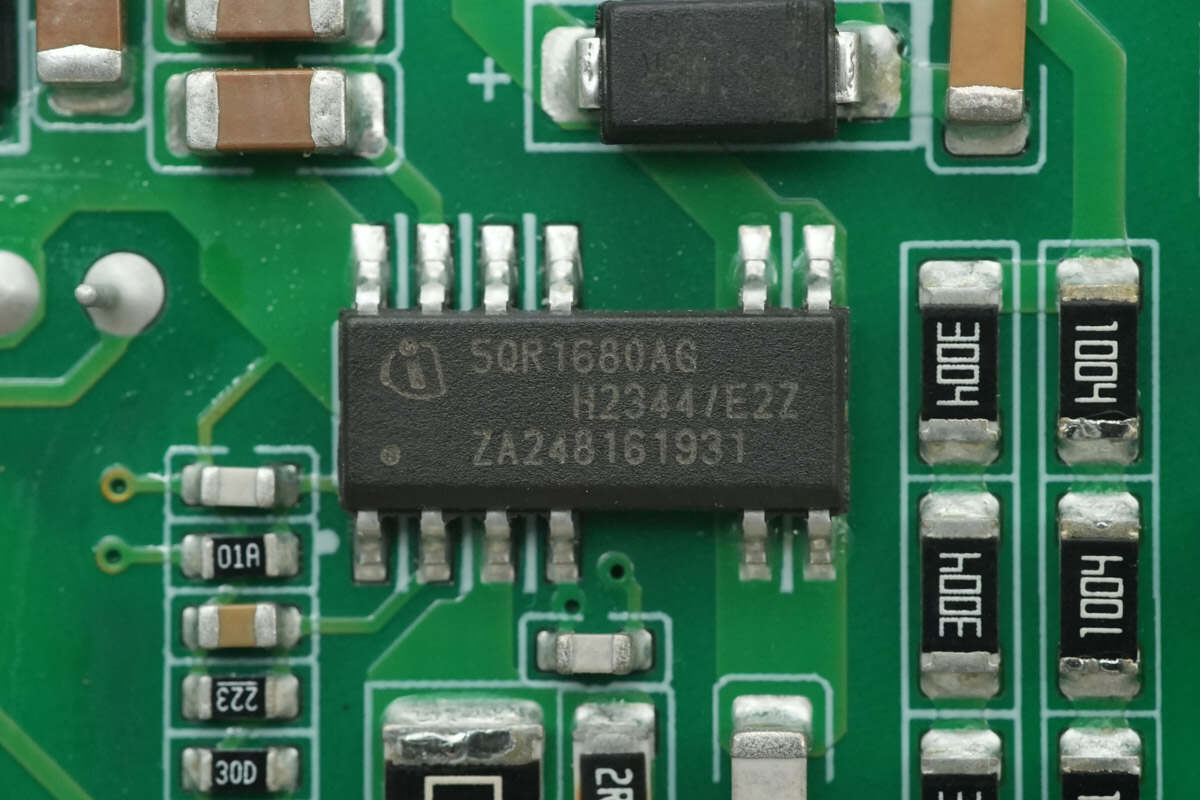
The standby power supply chip is from Infineon, model ICE5QR1680AG. It integrates an 800V MOSFET and supports up to 27W output power across a wide input voltage range. The chip comes in a DSO-12 package.
An insulating plastic case is installed at the bottom of the transformer.
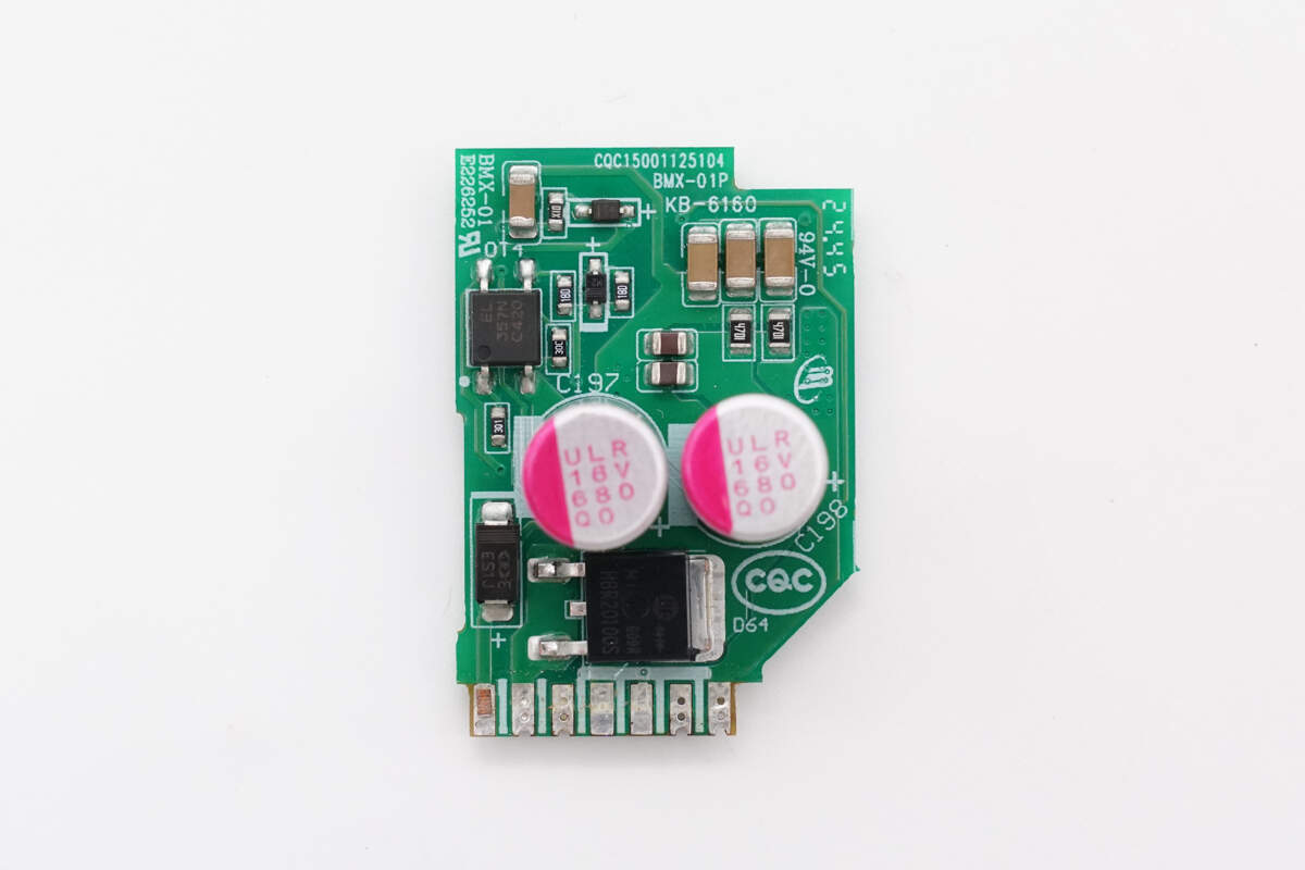
On the front side of the vertical PCB, there are rectifier diodes, solid capacitors, and an SMD optocoupler.
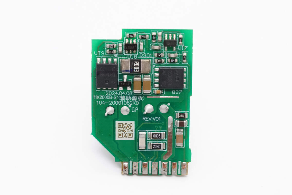
On the back side, there are MOSFETs and a current-sensing resistor.
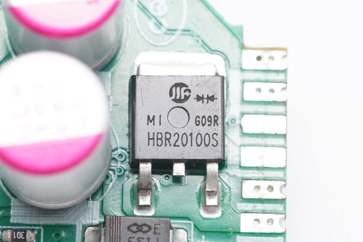
One diode is from Sino-microelectronics, model HBR20100S, rated for 20A and 100V, and comes in a DPAKM package.
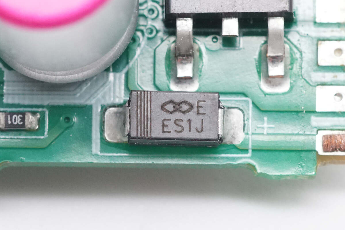
Another diode is from Gulf Semiconductor, model ES1J, rated for 600V and 1A, and comes in an SMA package.
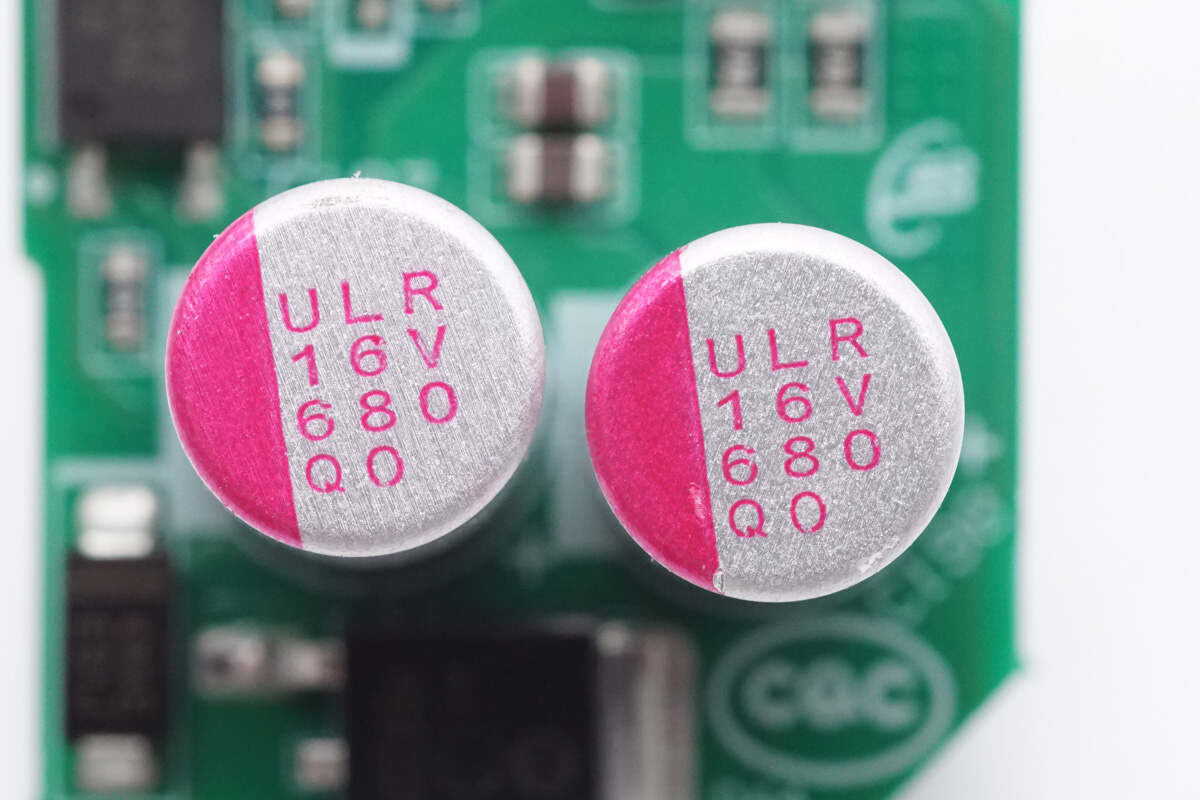
Both filter capacitors are rated at 16V, 680μF.
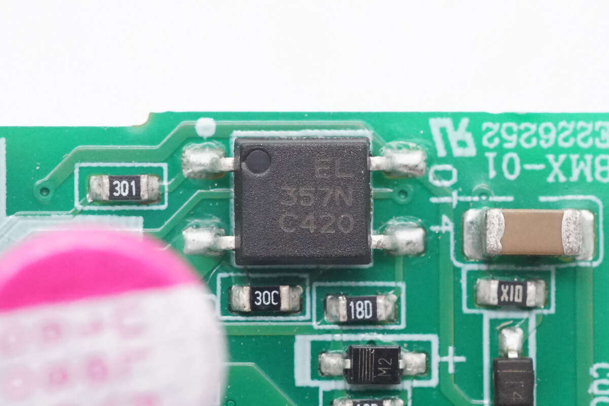
Close-up of the Everlight EL357 optocoupler.
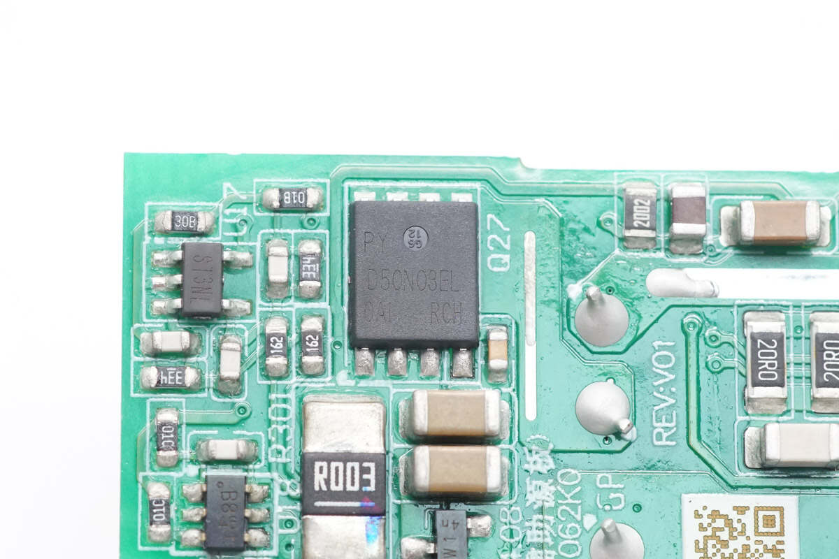
The MOSFET used for power control is from Pingwei, model D50N03EL.
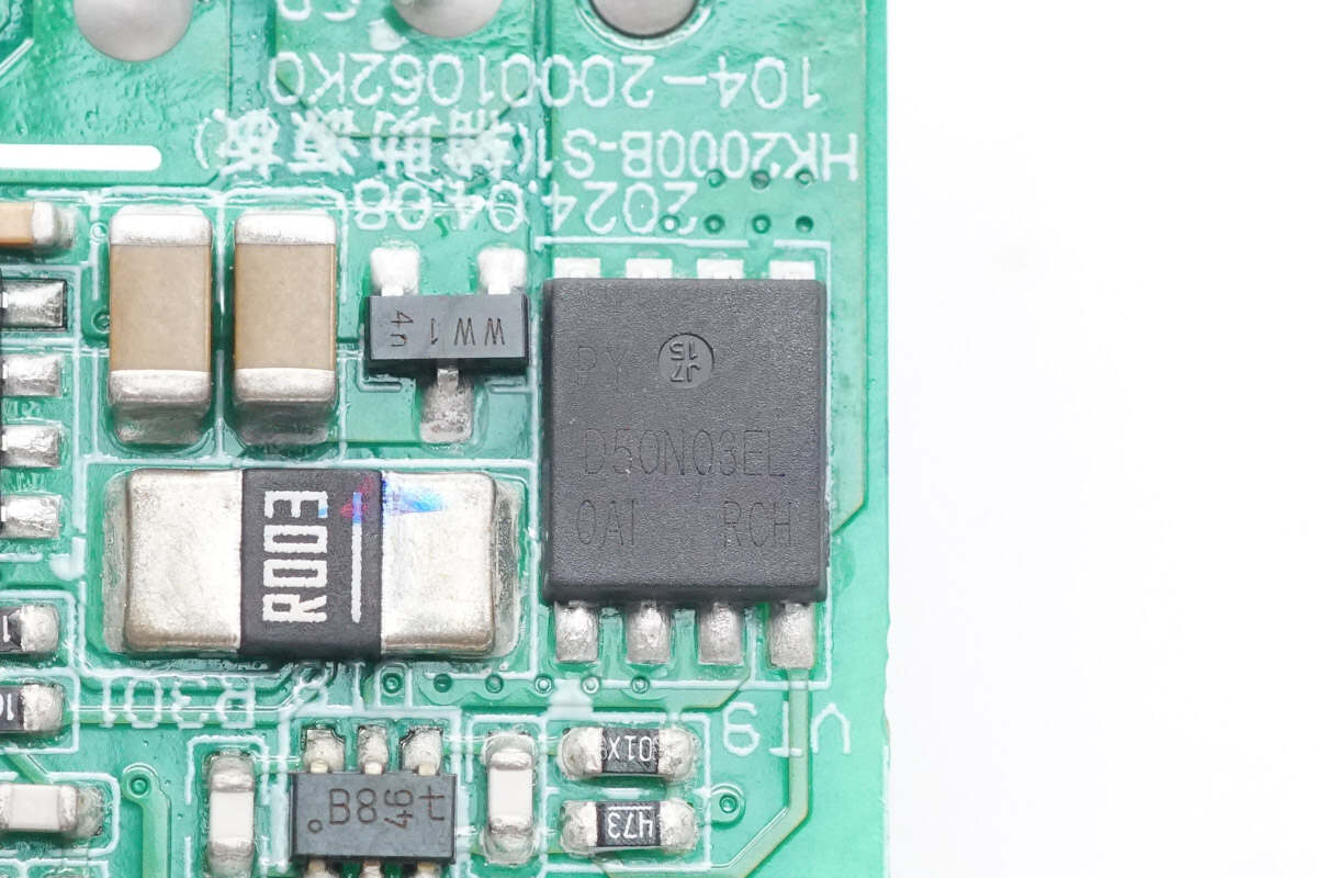
The other MOSFET is of the same model.
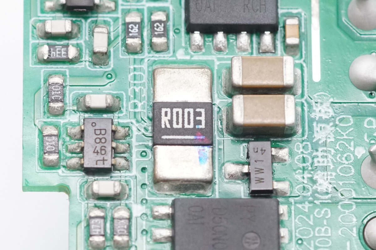
Close-up of the 3mΩ current sampling resistor.
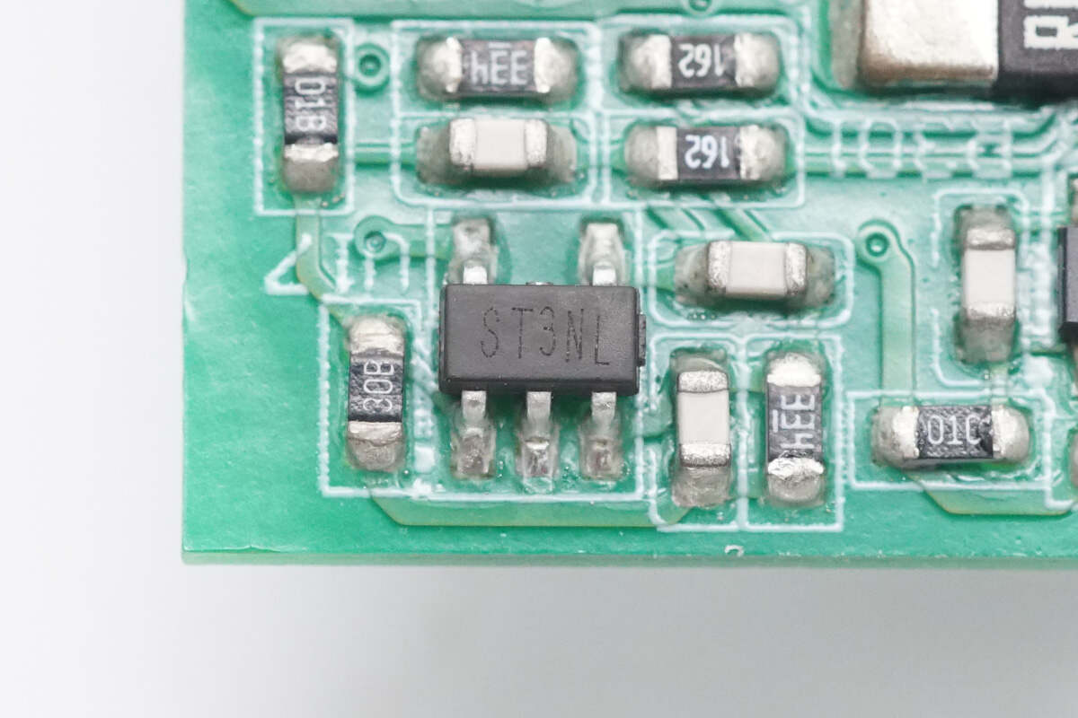
Close-up of the chip marked with ST3NL.
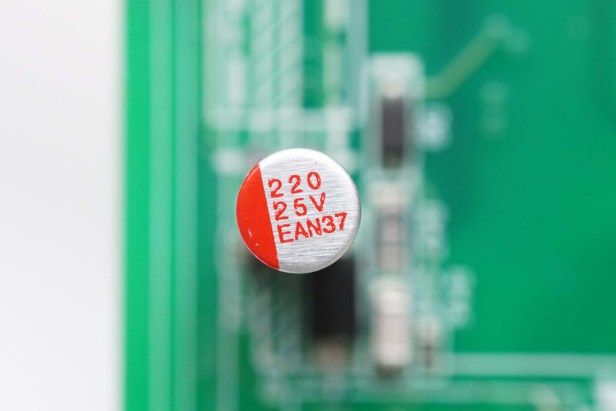
The filter capacitor specification is 220μF25V.
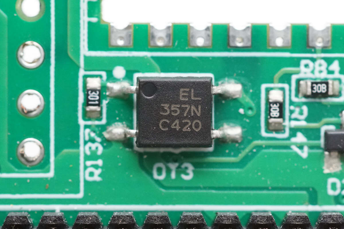
An Everlight EL357 optocoupler is used for output voltage feedback.
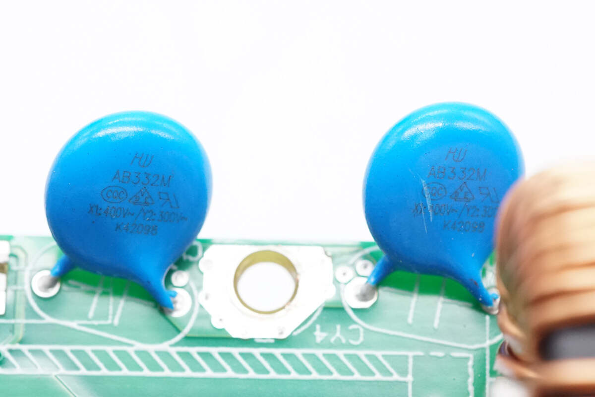
The two blue Y capacitors are grounded through the screws.
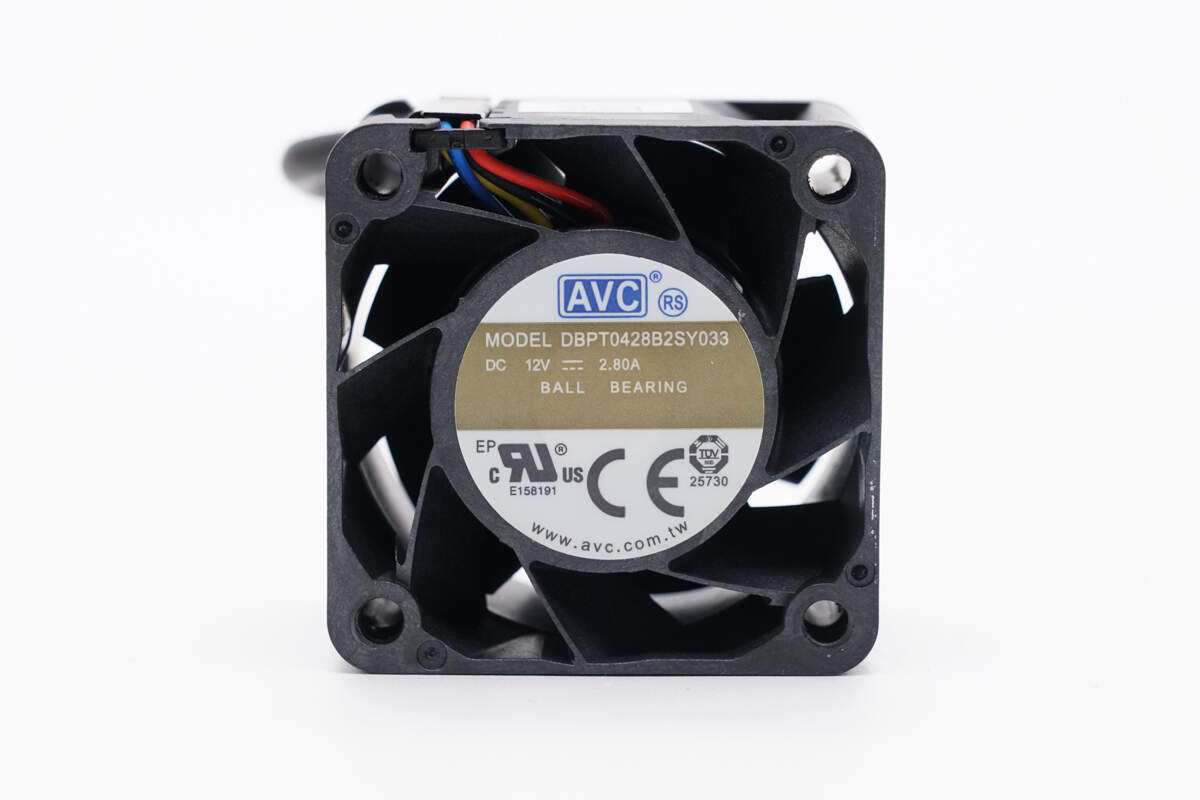
The cooling fan is from AVC, model DBPT0428B2SY033, specification is 12V 2.8A, and has built-in ball bearings.
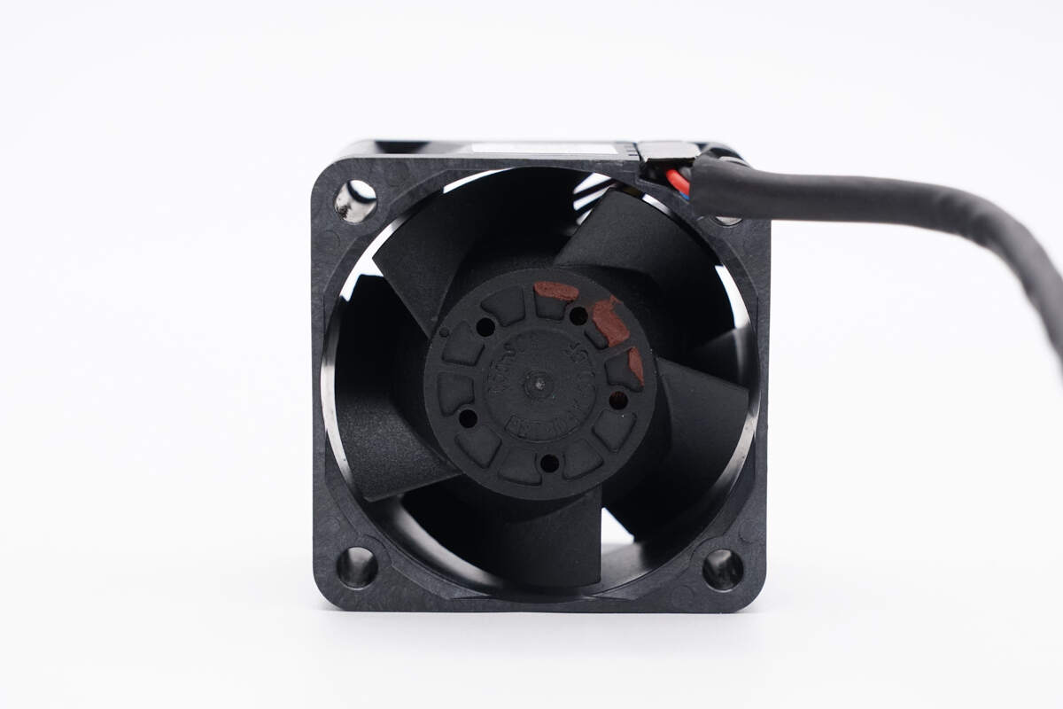
The fan rotor is coated with dynamic balancing adhesive.
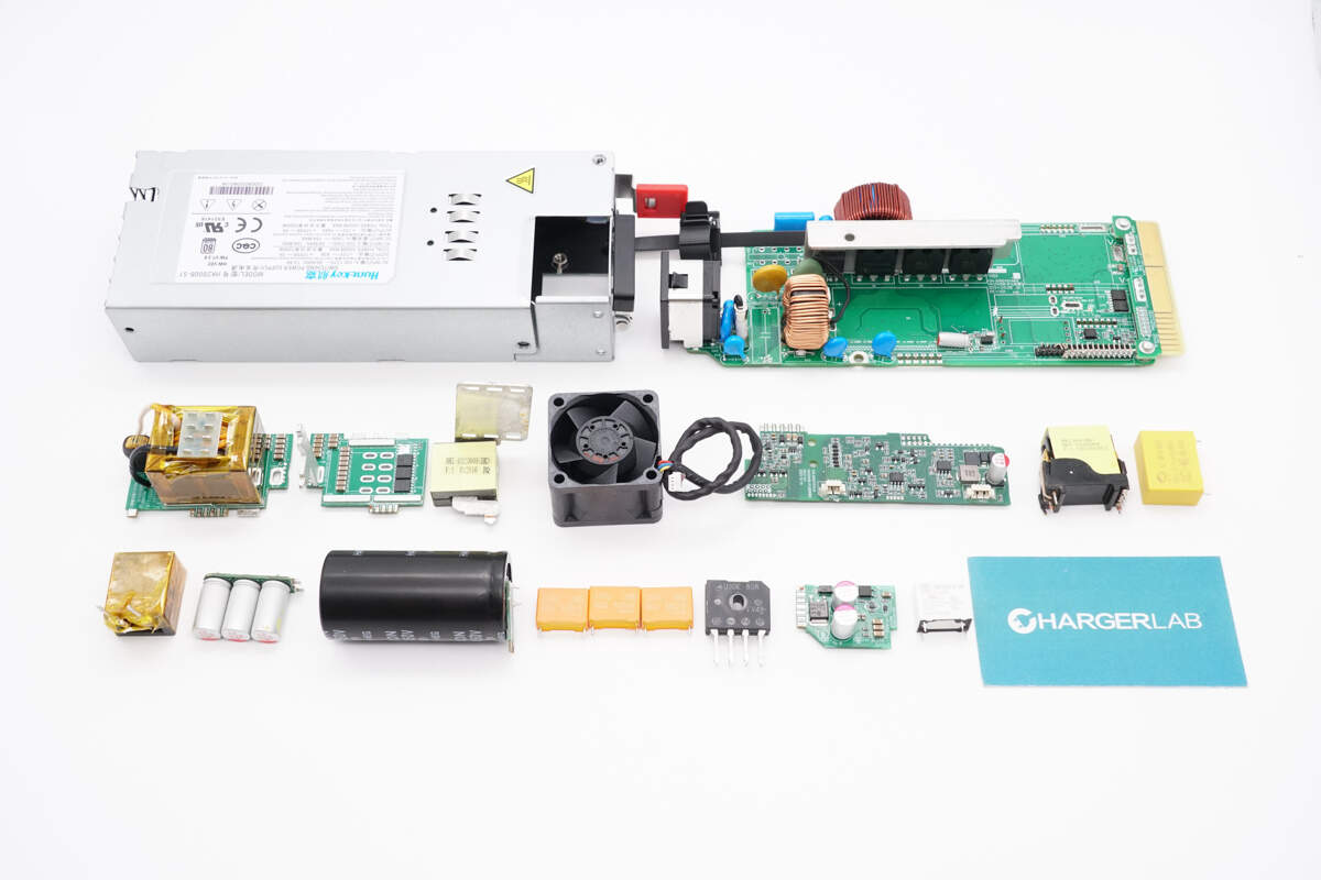
Well, those are all components of the Huntkey 2000W 80 PLUS Platinum Switching Power Supply.
Summary of ChargerLAB
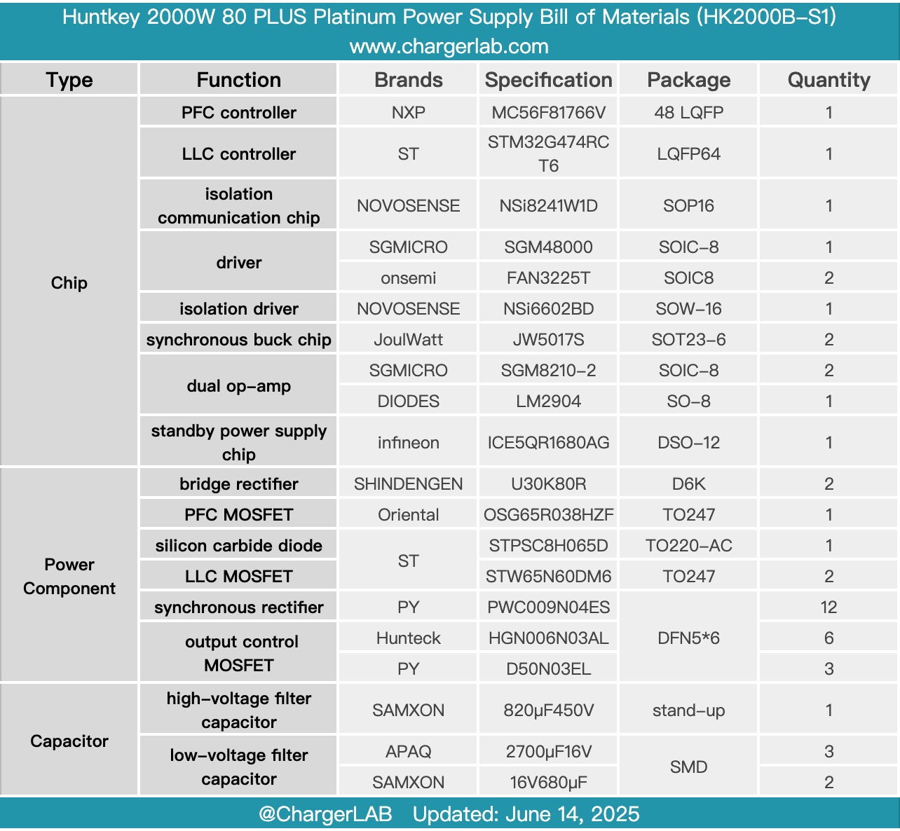
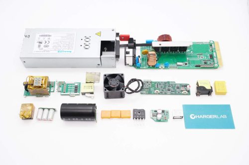
Here is the component list of the Huntkey 2000W 80 PLUS Platinum Switching Power Supply for your convenience.
It supports a wide input voltage range with a rated output power of 2000W. The input side has a pin-type connector and an indicator light. The output side features PCB gold fingers. Inside, there is a cooling fan.
After taking it apart, we found that it adopts a PFC + LLC architecture. The PFC stage uses an NXP MC56F81766V controller, paired with an Oriental OSG65R038HZF MOSFET and an STMicroelectronics STPSC8H065D silicon carbide diode. The LLC stage is controlled by an STMicroelectronics STM32G474RCT6, working with STMicro STW65N60DM6 MOSFETs.
An SGMICRO SGM48000 driver drives the PFC MOSFET, while the LLC MOSFET uses a NOVOSENSE NSi6602BD isolated driver. The synchronous rectifier is driven by an Onsemi FAN3225T driver. The auxiliary power supply chip is an Infineon ICE5QR1680AG. SAMXON supplies high-voltage filtering capacitors, and solid capacitors are from APAQ. The internal layout is compact, and the build quality and component selection are solid and reliable.
Related Articles:
1. Teardown of UGREEN Revodok Max Thunderbolt 5 Docking Station (U715)
2. Teardown of Xiaomi 22.5W 5000mAh Magnetic Wireless Power Bank (WPB0507S)
3. Teardown of HUAWEI 3000W R4850G1 Power Supply Unit