Introduction
Today, we take a teardown look at the GreatWall GW-CRPS3000L5R redundant server power supply. It supports 100–240V AC input as well as 240V HVDC input. The main output voltage is 54V with a rated output current of 55A. The standby power supply provides 12V output with a current of 2A.
On the input side, the power supply is equipped with a cooling fan, an AC inlet, and status indicators. The output side features a gold-finger connector and supports hot-swap operation. The power supply adopts a bridgeless PFC + full-bridge LLC + synchronous rectification topology and supports PMBus communication. Next, let’s take a closer look at its internal components and design.
Product Appearance
The enclosure is made of galvanized steel sheets and secured with screws.
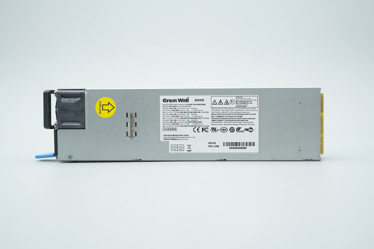
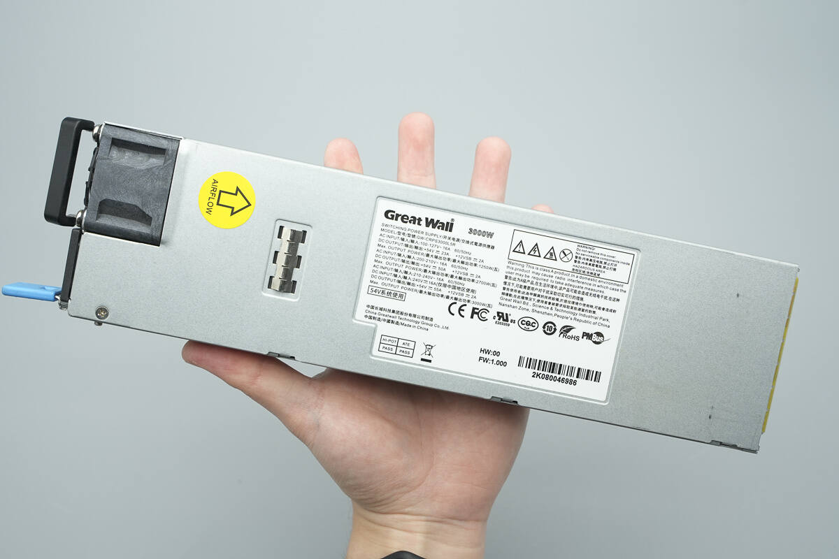
An airflow direction label and an information label are affixed to the front side.
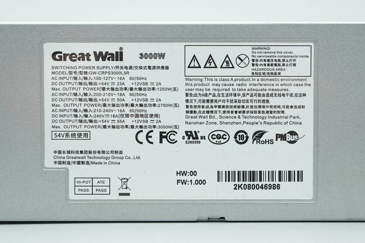
Model: GW-CRPS3000L5R
Input: 100–127 V~ 16 A 60/50 Hz
Output: +54 V ⎓ 23 A, +12 VSB ⎓ 2 A
Maximum output power: 1250 W
Input: 200–210 V~ 16 A 60/50 Hz
Output: +54 V ⎓ 50 A, +12 VSB ⎓ 2 A
Maximum output power: 2700 W
Input: 210–240 V~ 16 A 60/50 Hz
Input: 240 V ⎓ 16 A (for use in China only)
Output: +54 V ⎓ 55 A, +12 VSB ⎓ 2 A
Maximum output power: 3000 W
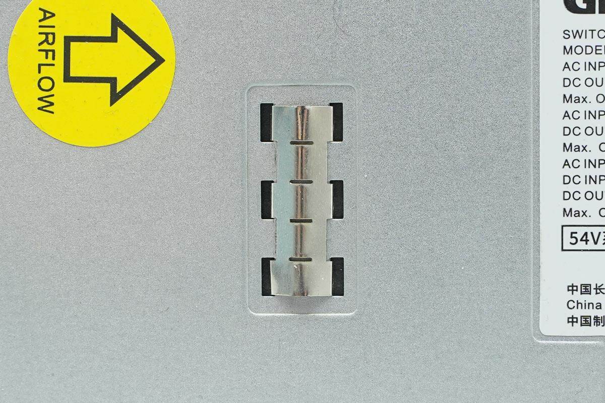
Close-up view of the grounding spring contacts.
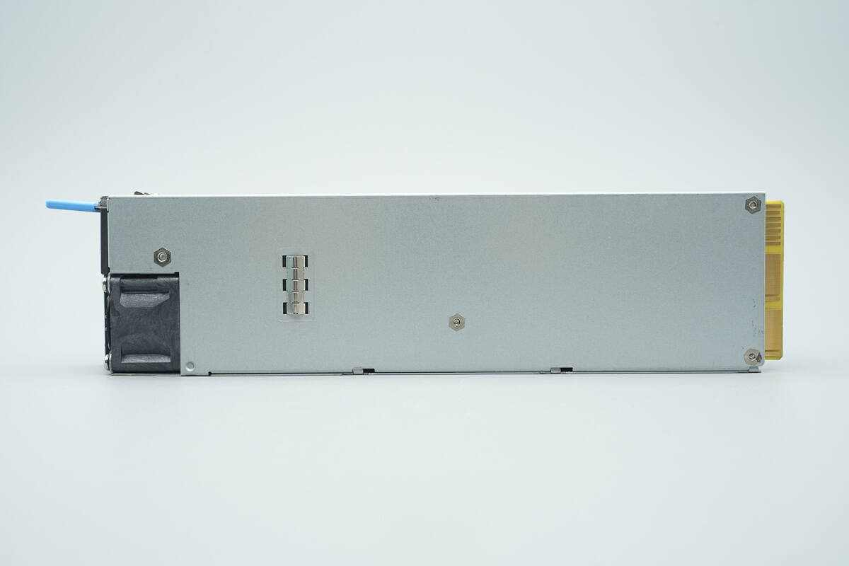
The rear side is also equipped with grounding spring contacts.
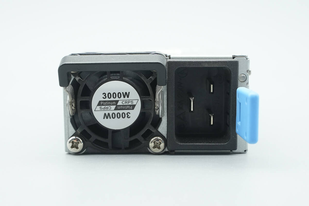
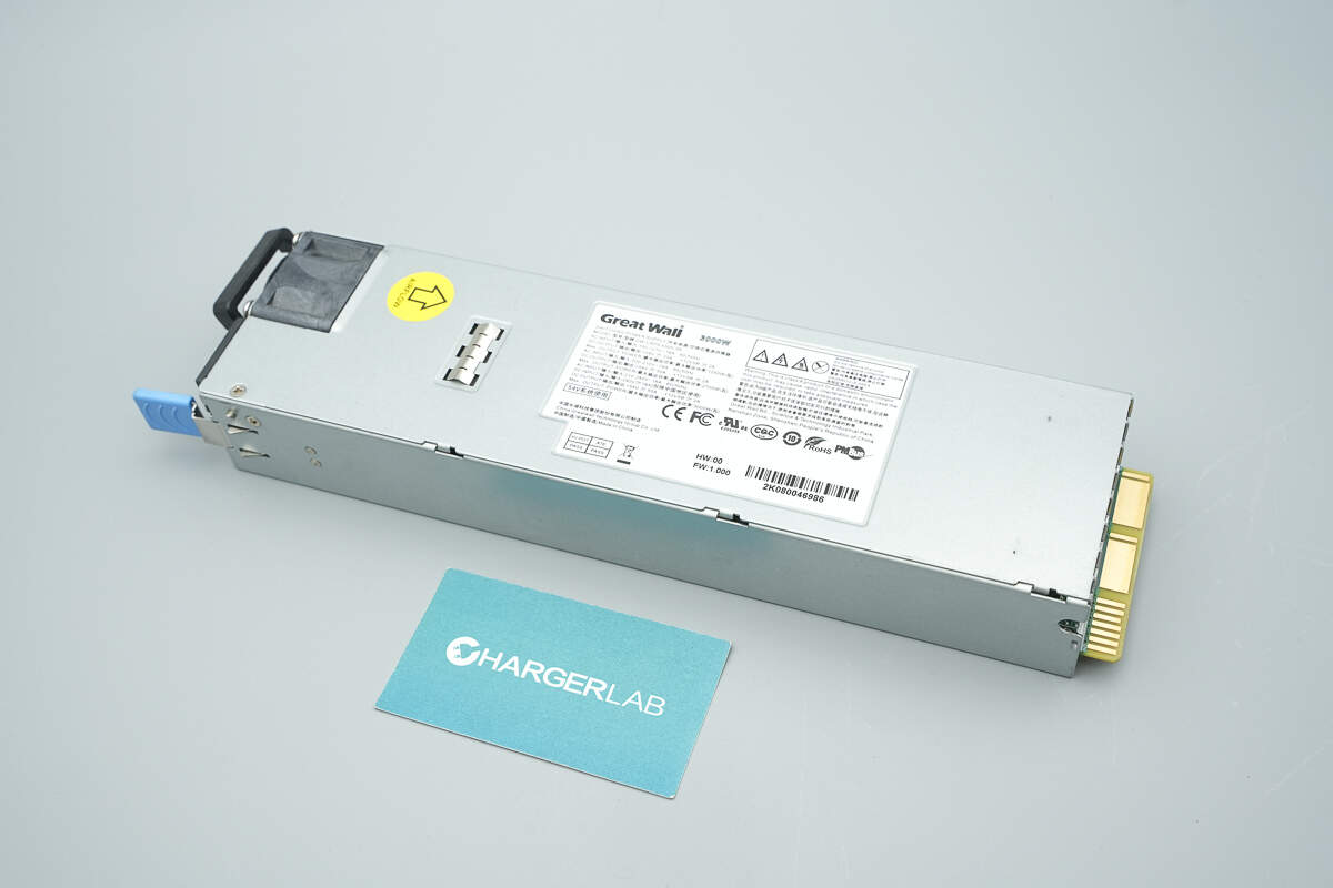
The input side features a handle, a cooling fan, an input socket, a power indicator, and a latch handle.
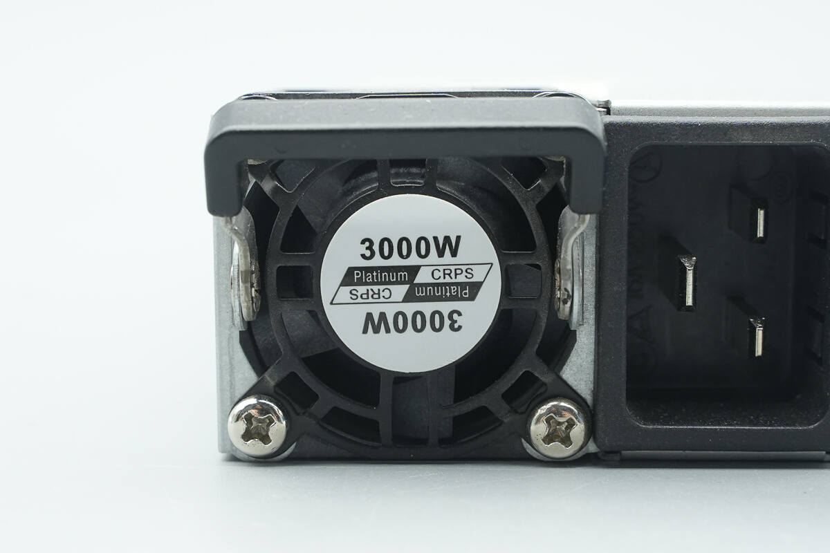
The fan guard is labeled with "Platinum CRPS" and "3000W".
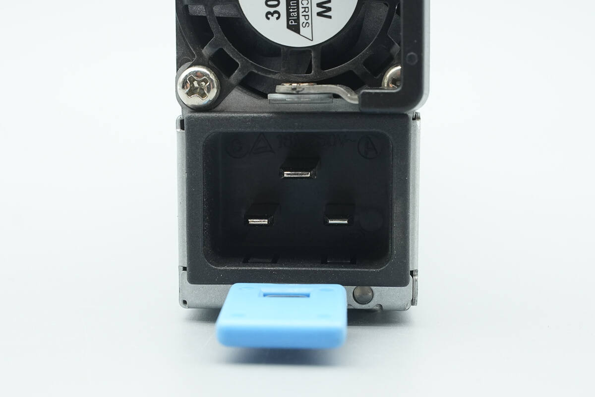
The input socket is a C20 type, and the LED indicator is located at the bottom right corner.
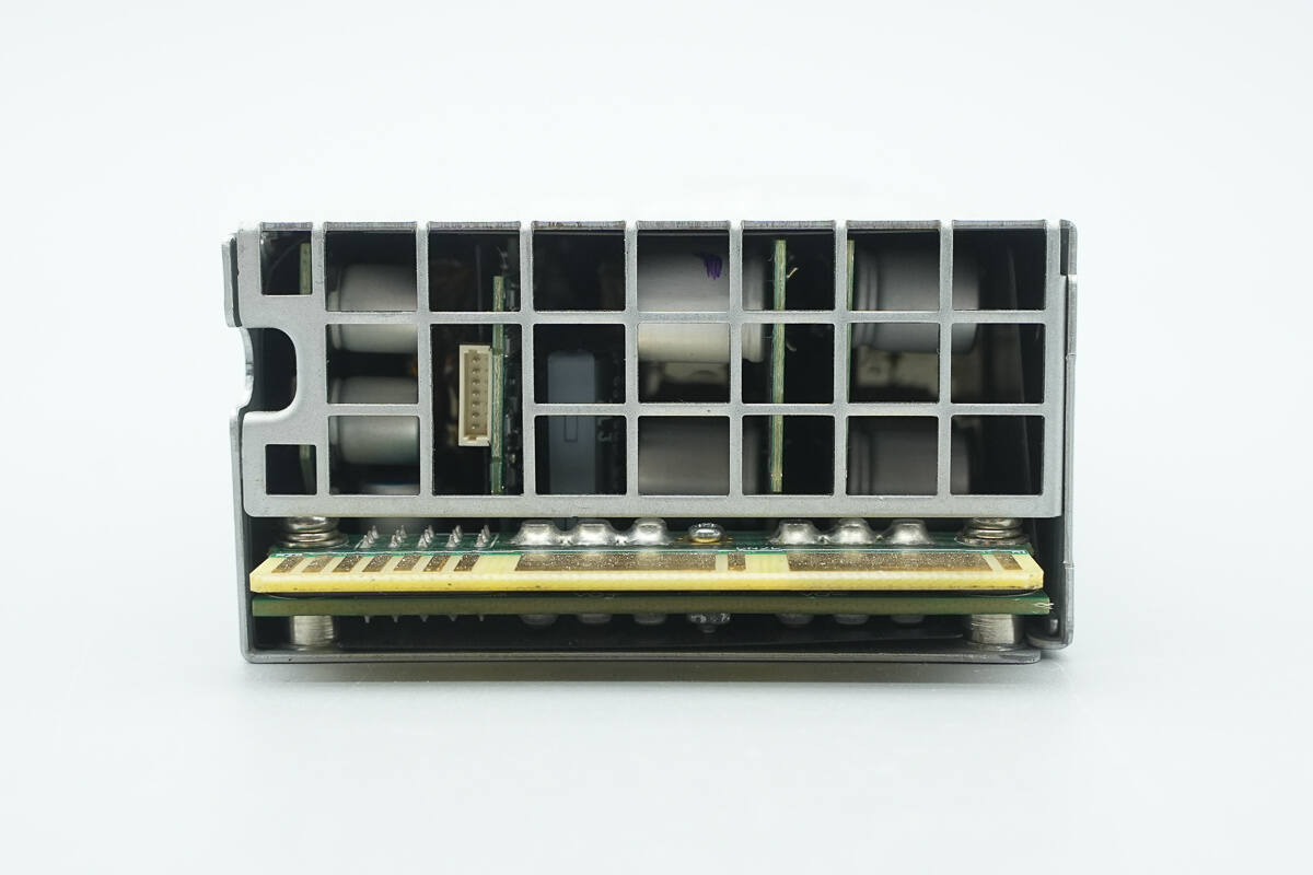
The output side features a gold-finger connector, and internal components are visible through the grille.
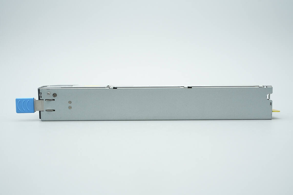
The side is equipped with mounting clips.
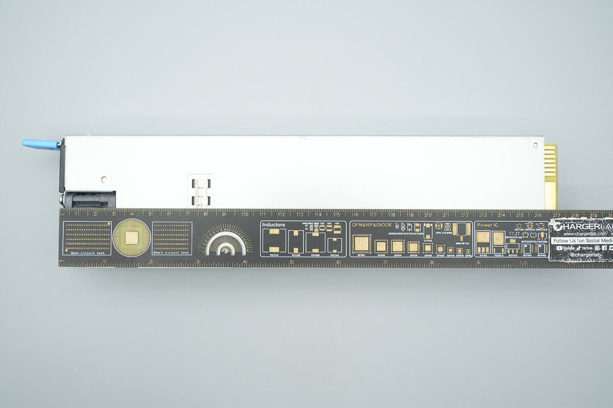
The length of the power supply is about 265 mm (10.43 inches).
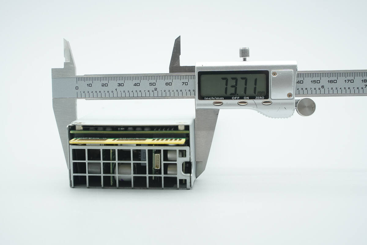
The width is about 73.7 mm (2.9 inches).
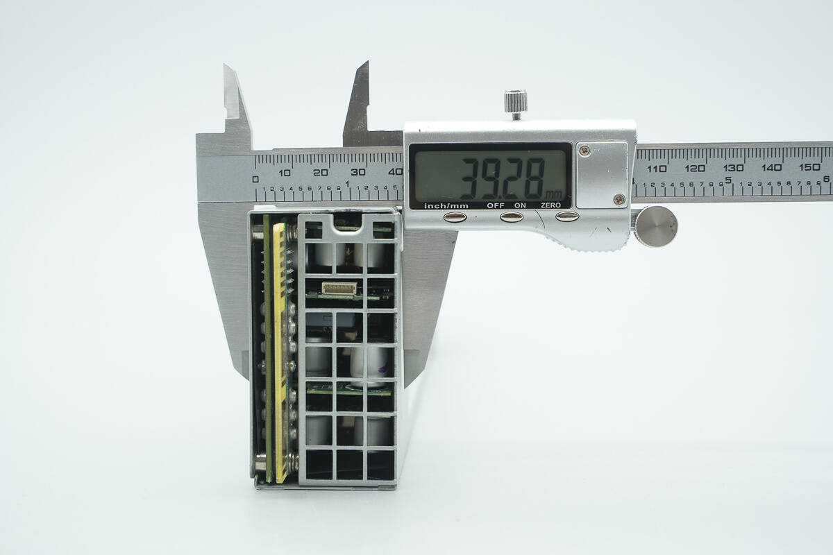
The thickness is about 39.3 mm (1.55 inches).
That's how big it is in the hand.
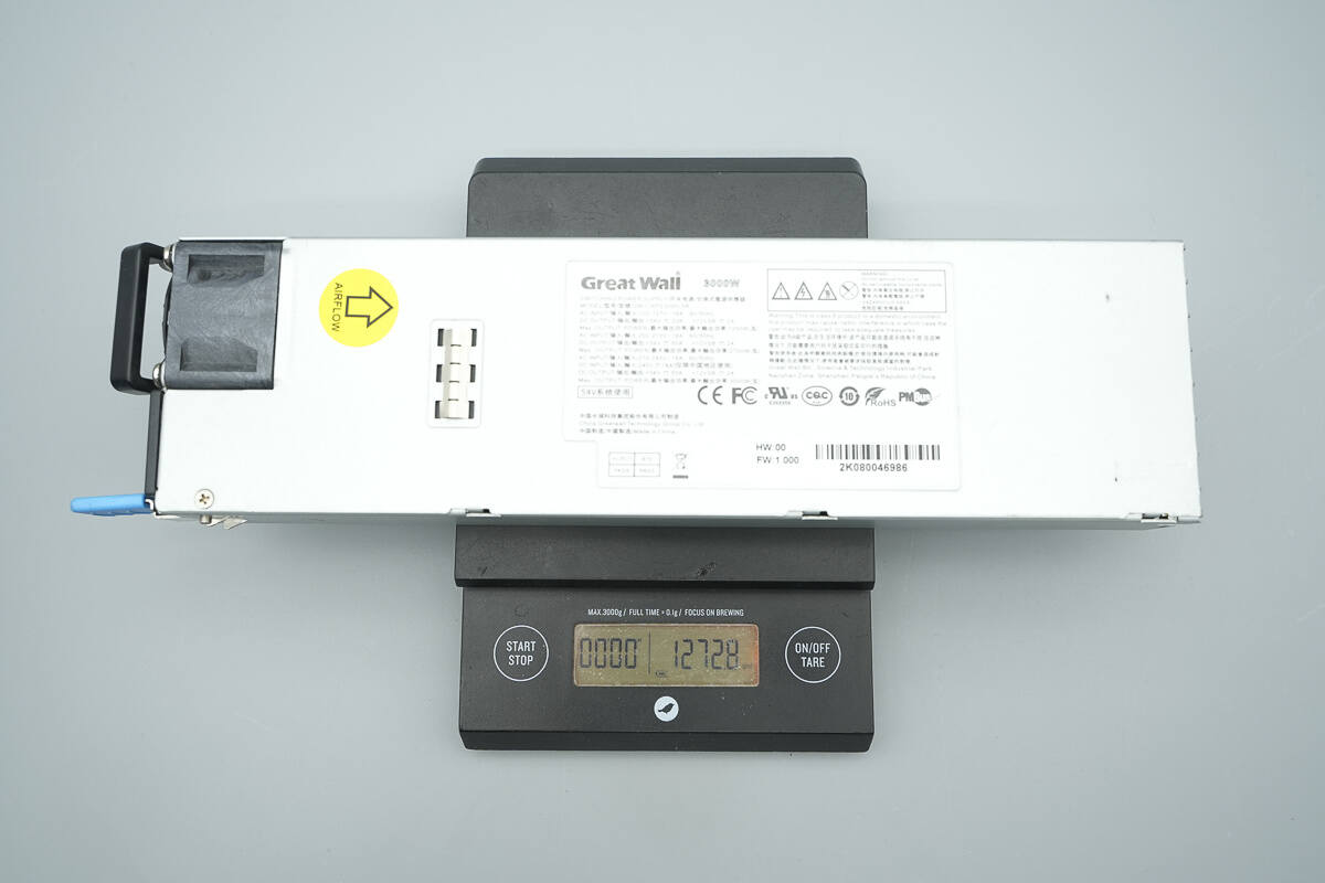
The weight is about 1273 g (44.9 oz).
Teardown
Next, let's take it apart to see its internal components and structure.
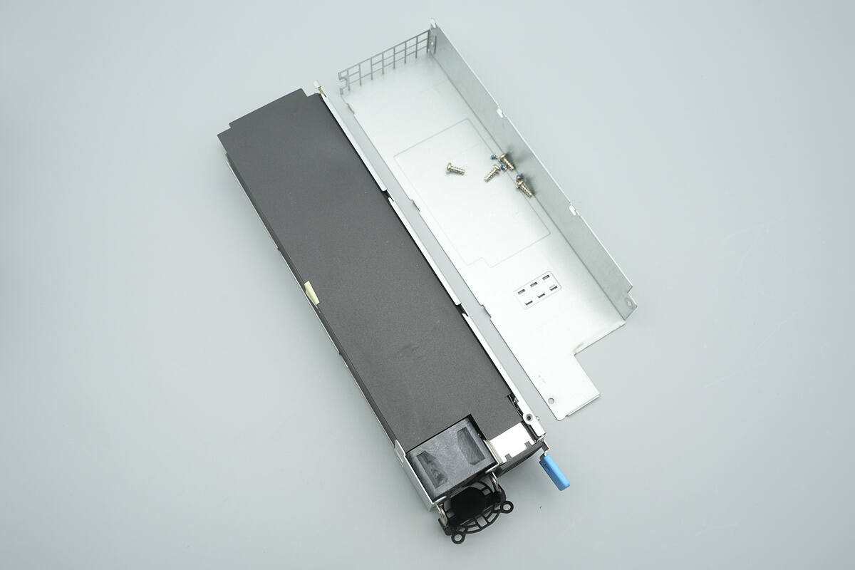
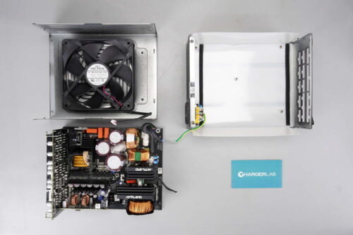
Unscrew the screws and remove the enclosure.
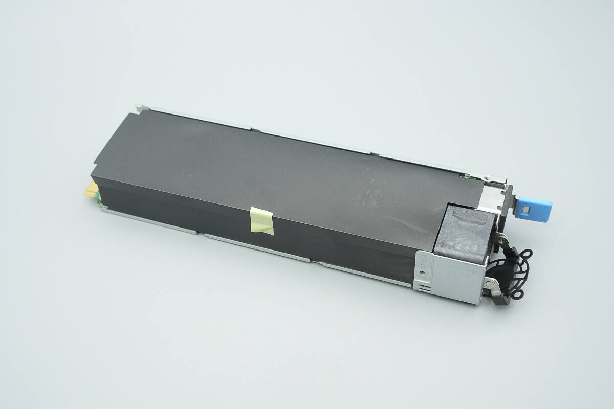
The PCBA module is fully wrapped in Mylar sheets.
Peel back the Mylar sheet.
The cooling fan and indicator LED are connected via connectors.
The PCBA module is secured inside the enclosure with screws.
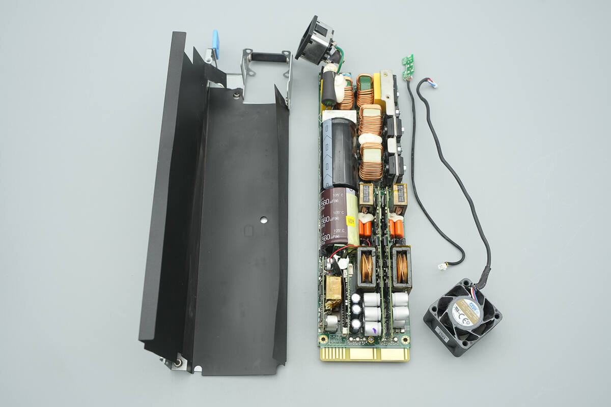
Remove the PCBA module.
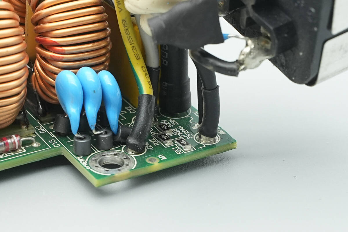
The input wires are cold-pressed to terminals and then soldered, with heat shrink tubing for insulation.
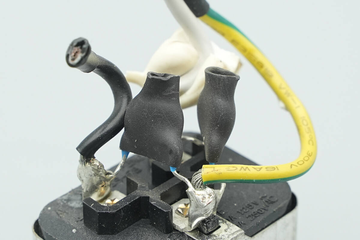
There are two blue Y capacitors on the input socket, each insulated with heat shrink tubing.
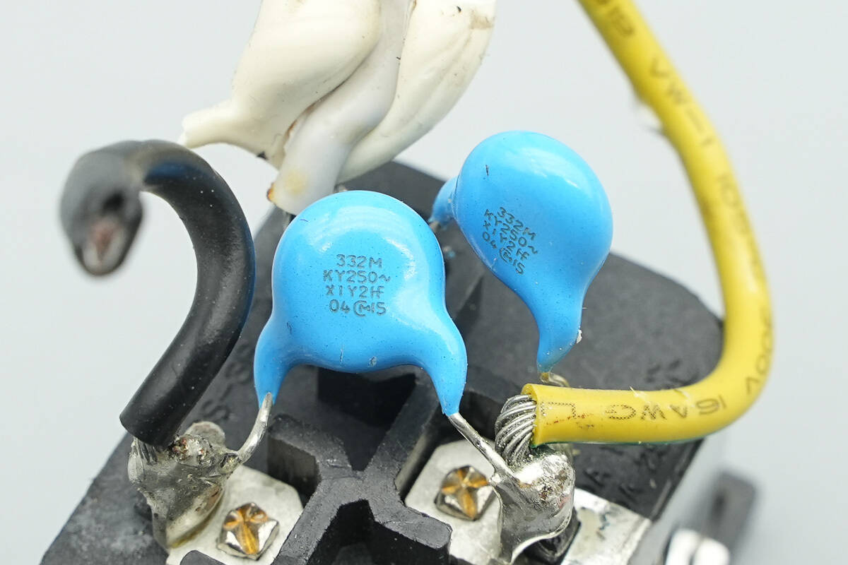
The two blue Y capacitors are from MURATA.

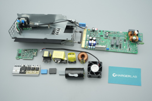
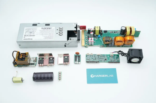
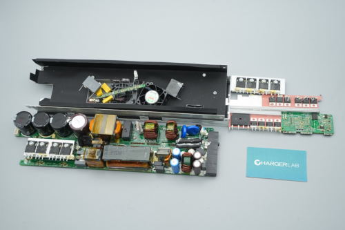
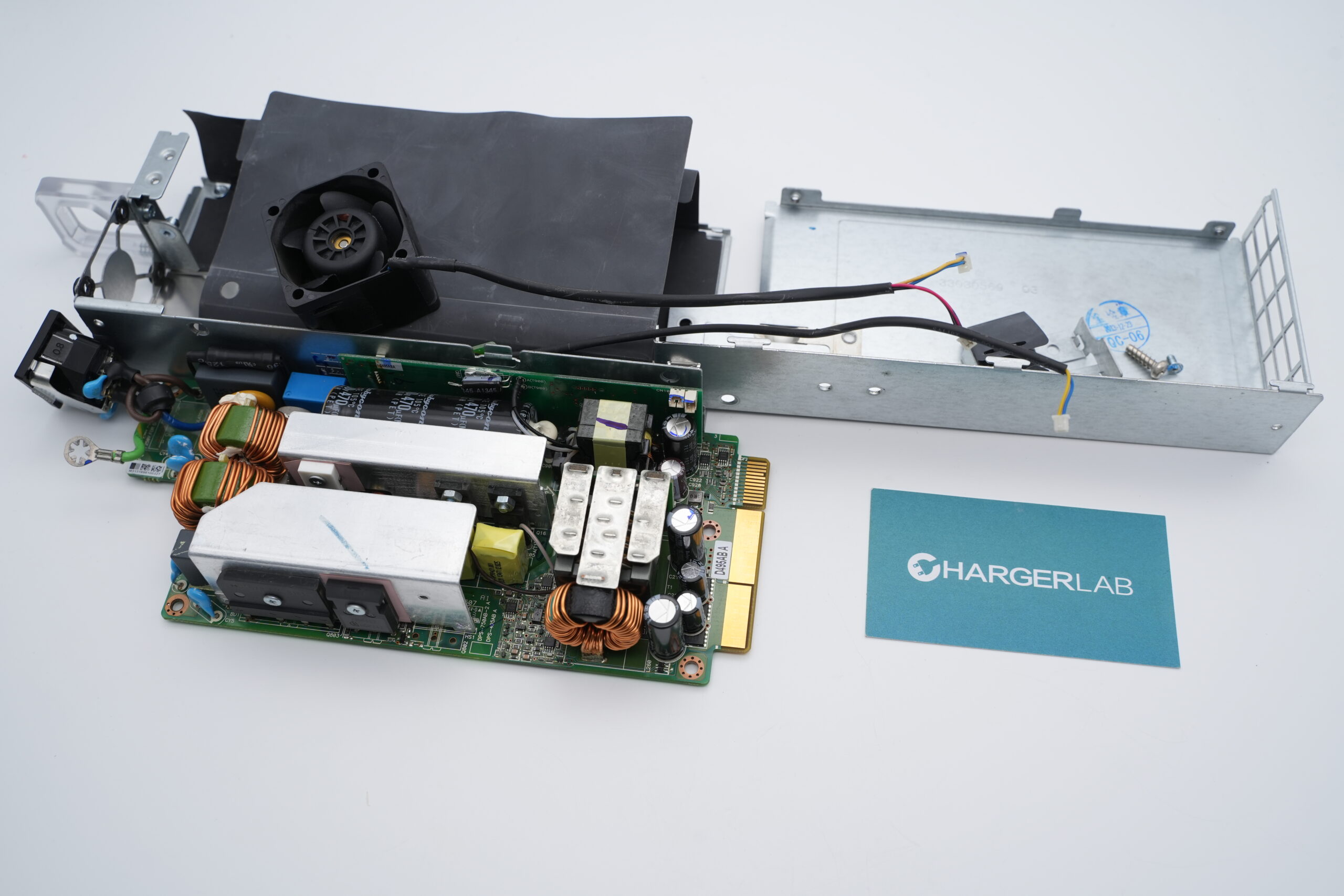
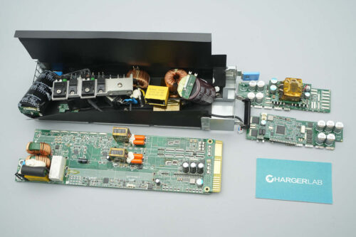
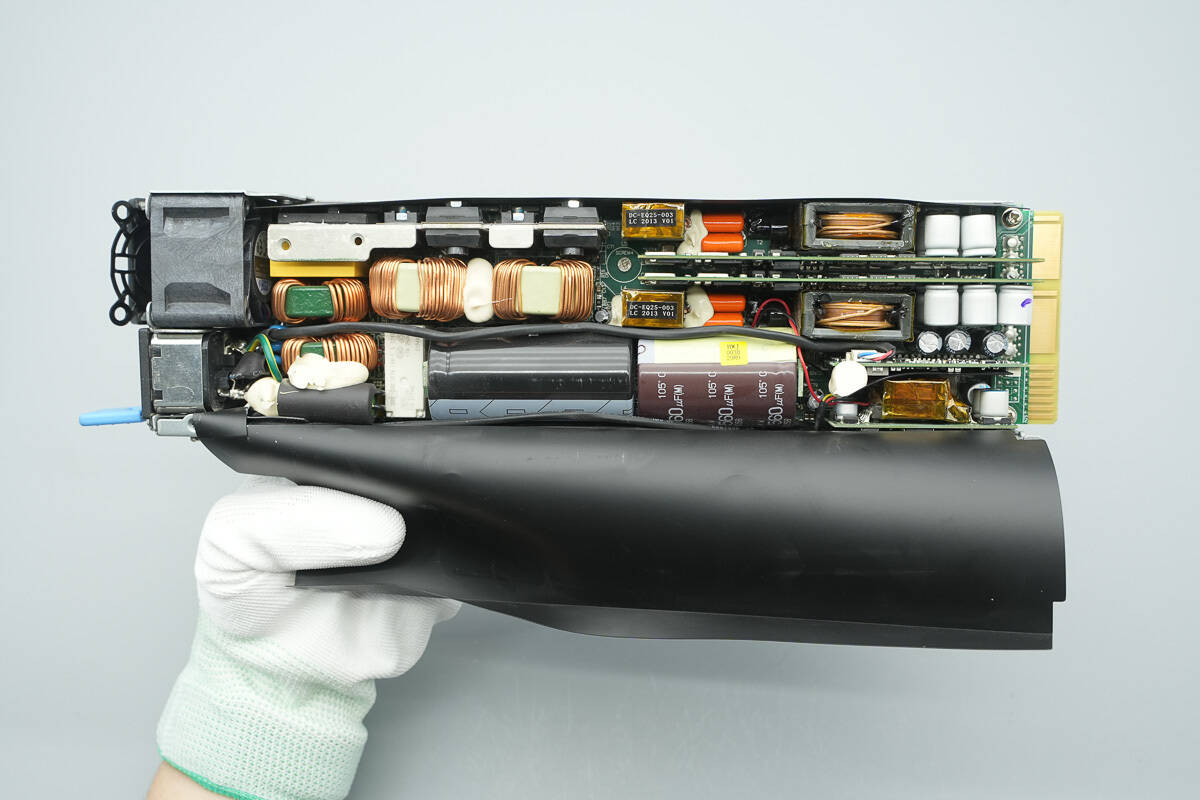
The front side of the PCBA module features fuses, safety X2 capacitors, a relay, a start-up resistor, common mode chokes, a bridge rectifier, PFC MOSFETs, rectifiers, PFC boost inductors, high-voltage filter capacitors, and other components.
On the upper left side, there is the standby power PCB and the LLC control PCB, while the lower section houses transformers, resonant capacitors, resonant inductors, and other components.
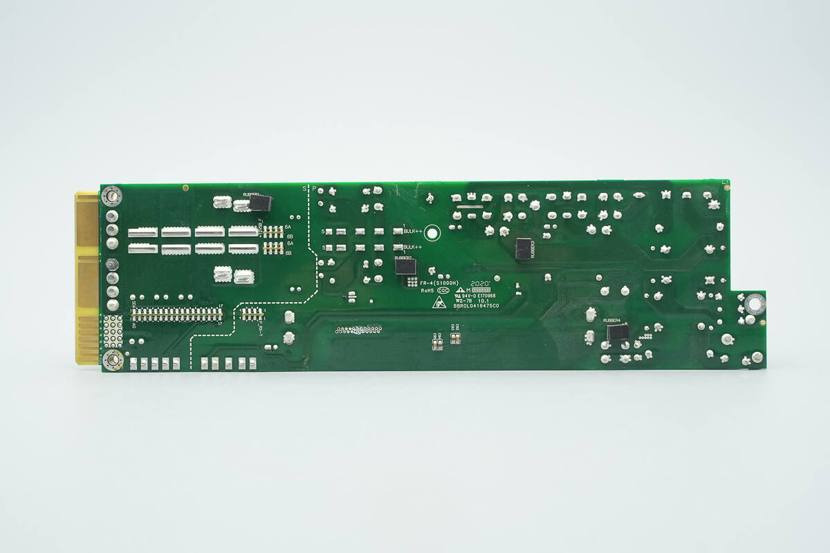
On the rear side, the primary and secondary sections are delineated by a dashed line.
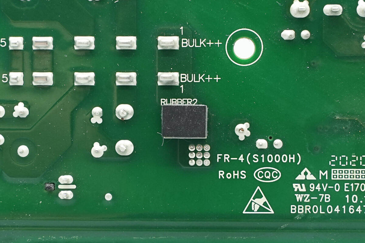
Close-up of the rubber pads on the rear side.
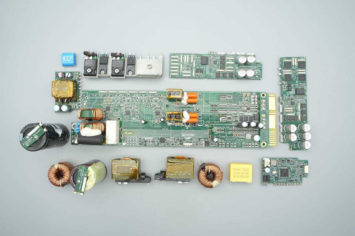
Remove most of the components.

The input fuse is insulated with heat shrink tubing.
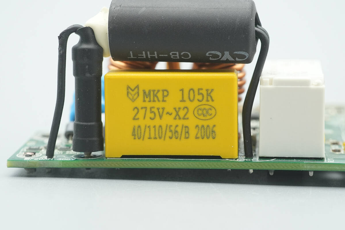
The safety X2 capacitor is rated at 1 μF.
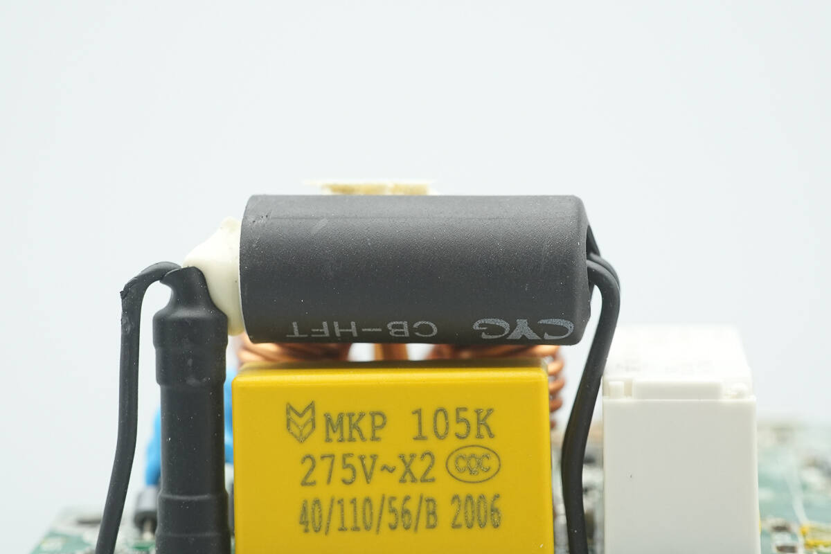
A start-up resistor is installed above the safety X2 capacitor, insulated with heat shrink tubing.
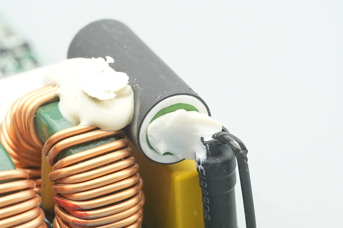
The start-up resistor is secured with adhesive.
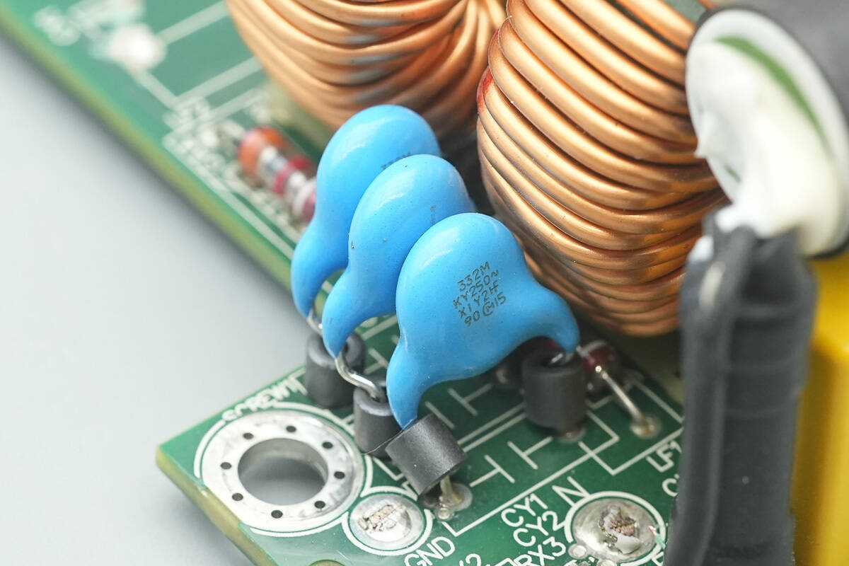
The blue Y capacitors are from MURATA, with their leads passing through ferrite beads to suppress high-frequency interference.
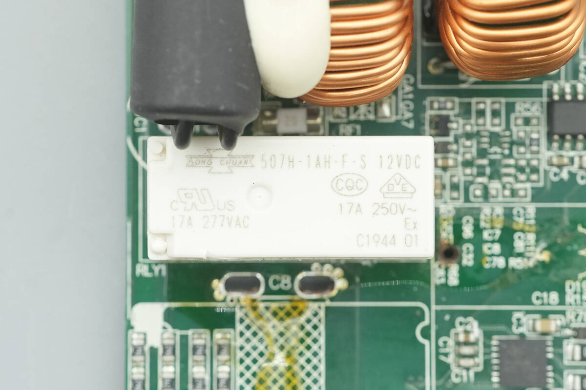
The relay is from SongChuan, model 507H-1AH-F-S-12VDC. It features a single normally open (NO) contact with a rating of 17 A 277 V, and a coil voltage of 12 V.
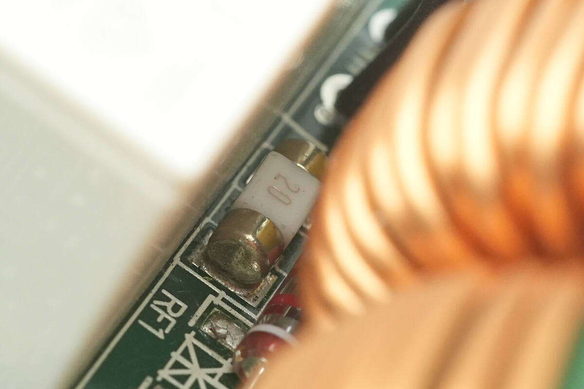
The SMD fuse is rated at 20 A.
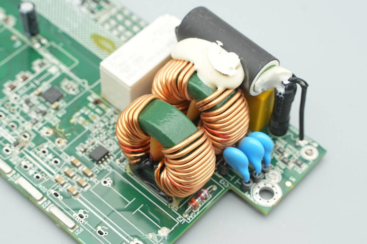
The two common mode chokes are wound with enameled wire, with a bakelite board installed at the bottom for insulation.
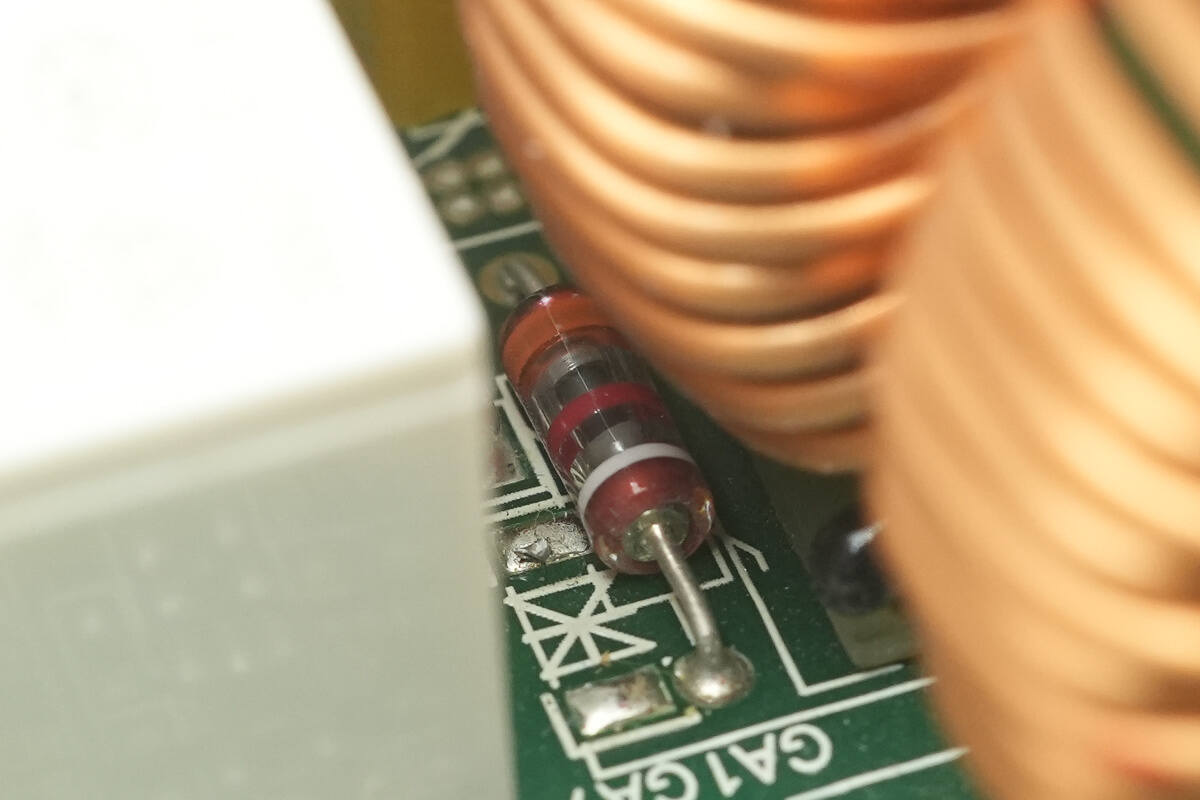
Gas discharge tubes are installed on both sides of the common mode chokes.
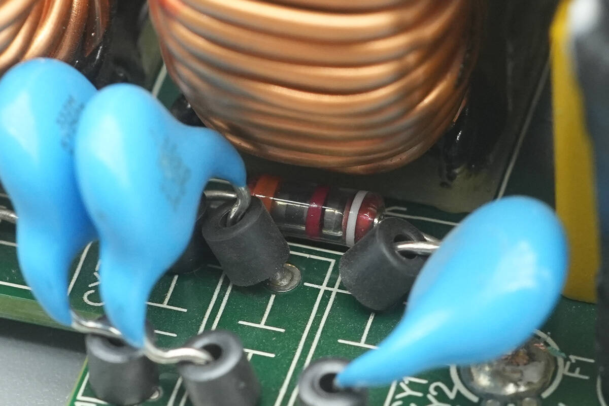
Close-up of the other gas discharge tube.
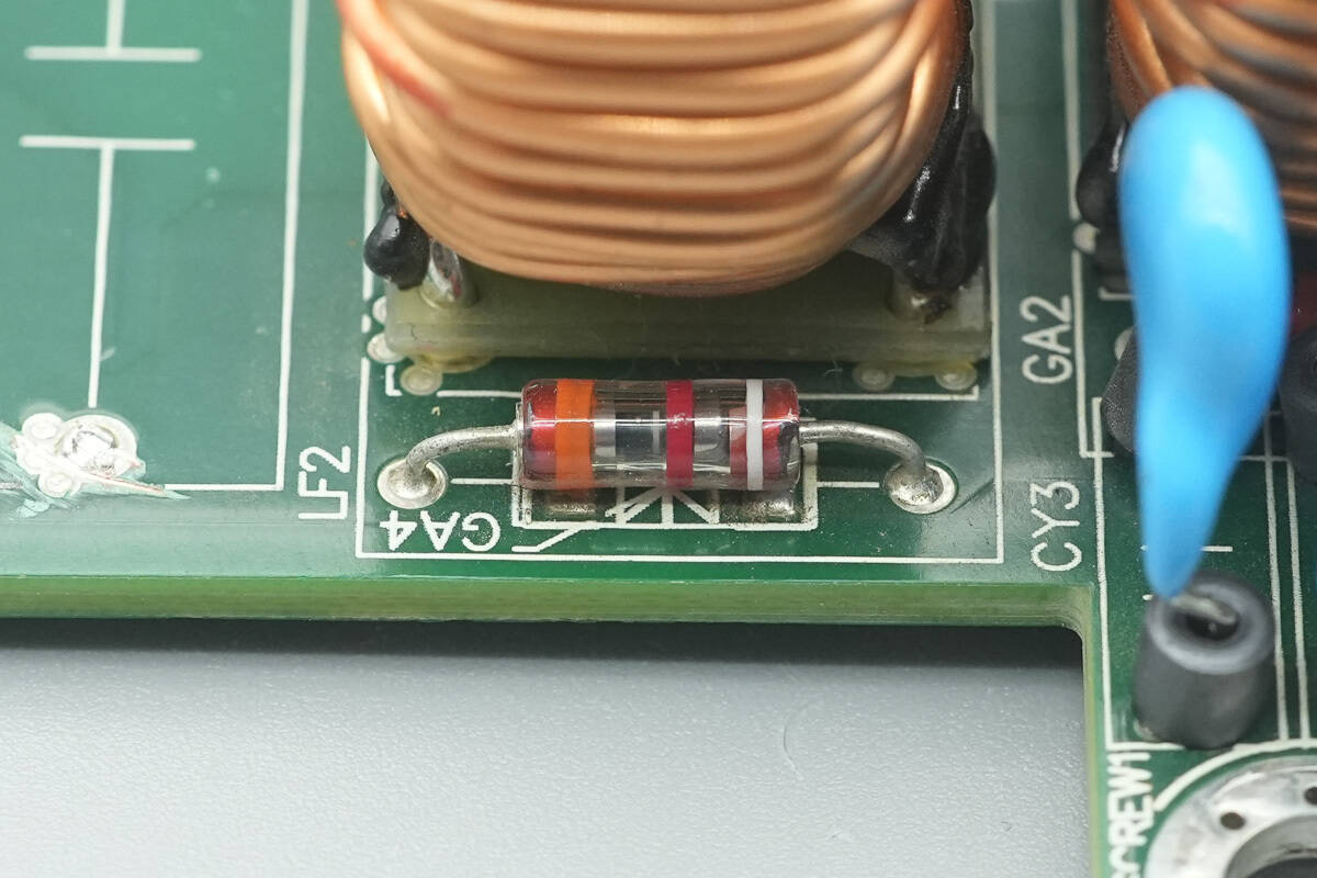
Gas discharge tubes are also installed on both sides of the other common mode choke.
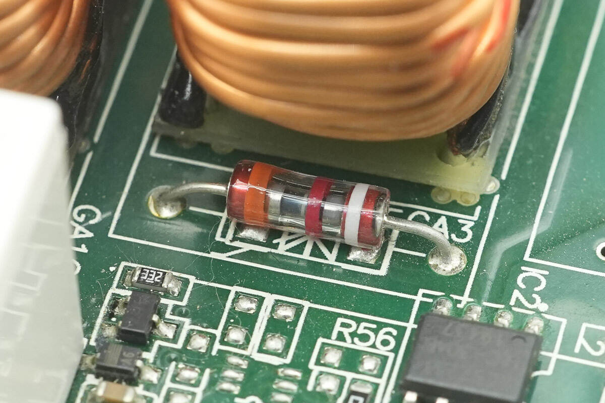
Close-up of the fourth gas discharge tube.
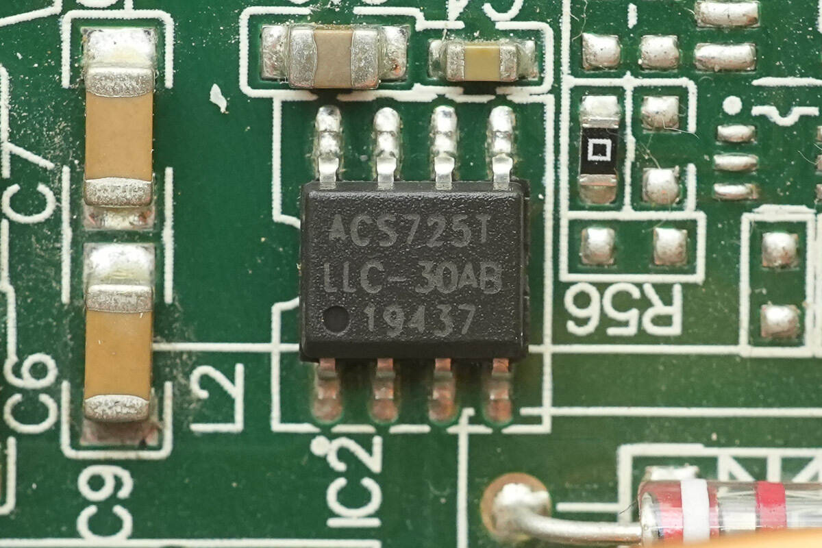
The current-sensing chip is from ALLERGO, model ACS725LLCTR-30AB-T. It is an automotive-grade isolated current sensor, compliant with the AEC-Q100 standard, with a measurement range of 30 A, a supply voltage of 3.3 V, and comes in an SOIC-8 package.
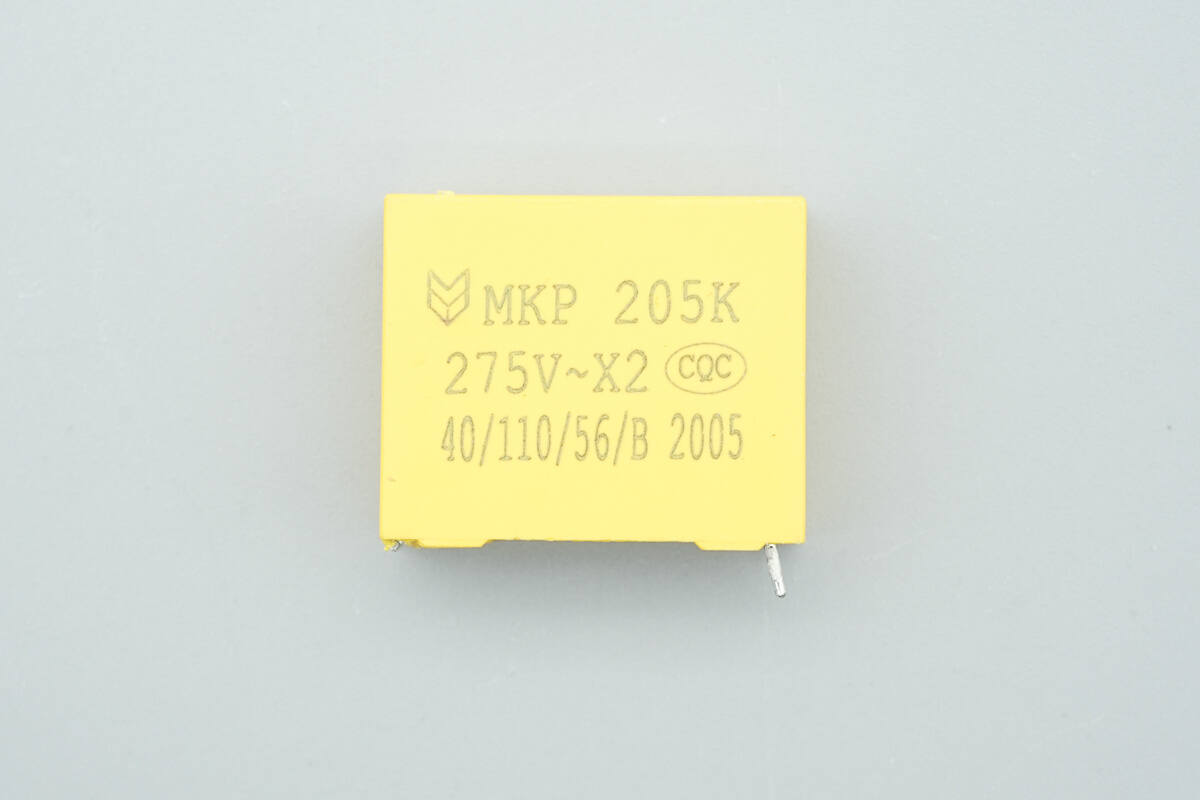
The safety X2 capacitor is rated at 2 μF.
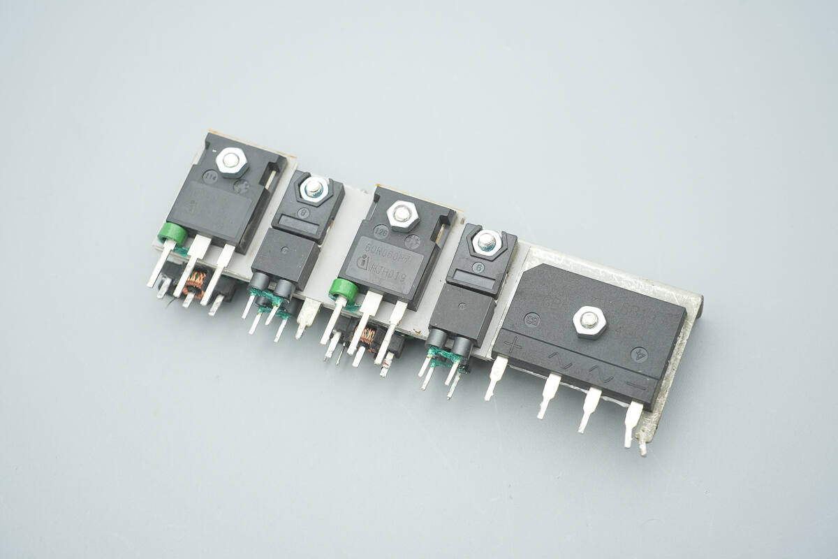
The front side of the heatsink features the bridge rectifier, PFC MOSFETs, and PFC rectifiers.
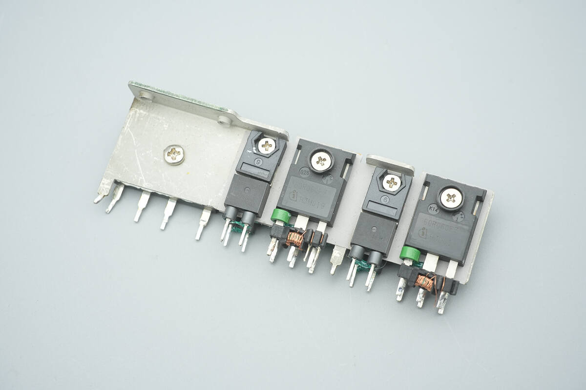
The other side houses PFC MOSFETs and PFC rectifiers.
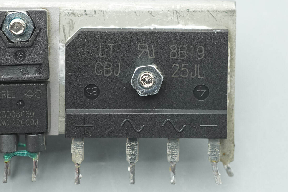
The bridge rectifier is from LITEON, model GBJ25JL. It is a low forward-voltage-drop bridge rectifier rated at 600 V/25 A, and comes in a GBJ package.
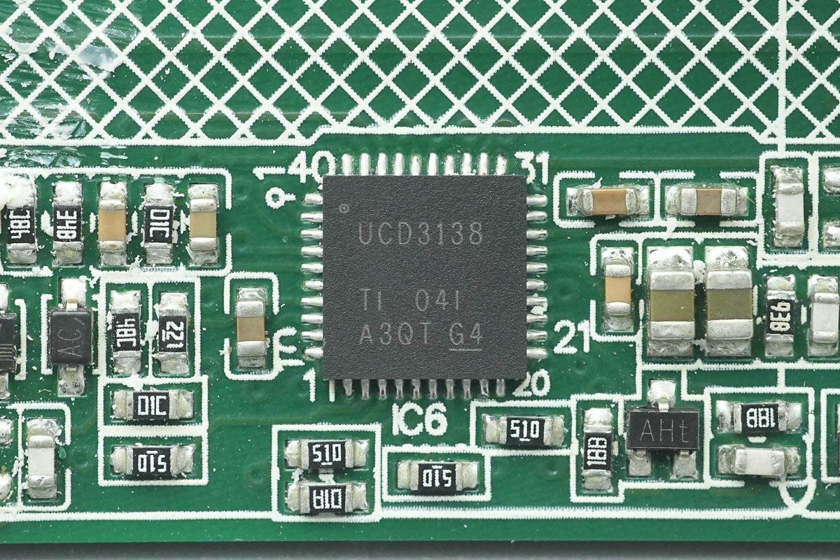
The PFC controller is from TI, model UCD3138. It is a highly integrated digital power controller featuring a high-performance 32-bit processor, 32 KB of internal flash memory, and interfaces including I²C, PMBus, and UART. It supports power supply and telecom rectifier applications, power factor correction, and DC-DC module applications, and comes in a QFN-40 package.
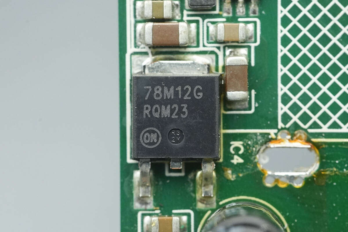
The voltage regulator is from Onsemi, model MC78M12. It supports an input voltage of 35 V, provides a 12 V output with a maximum current of 500 mA, and comes in a DPAK-3 package.
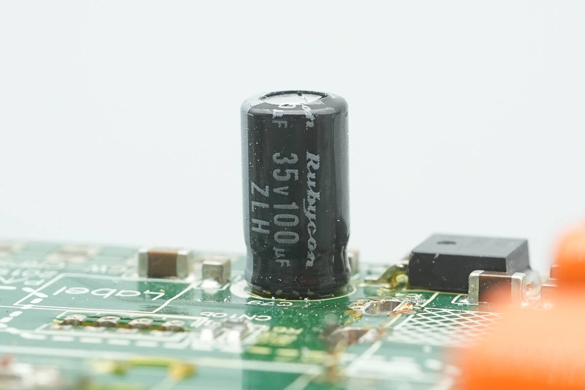
The filter capacitor is from Rubycon, rated at 35 V 100 μF.
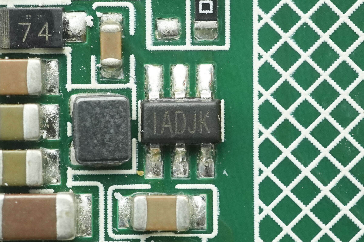
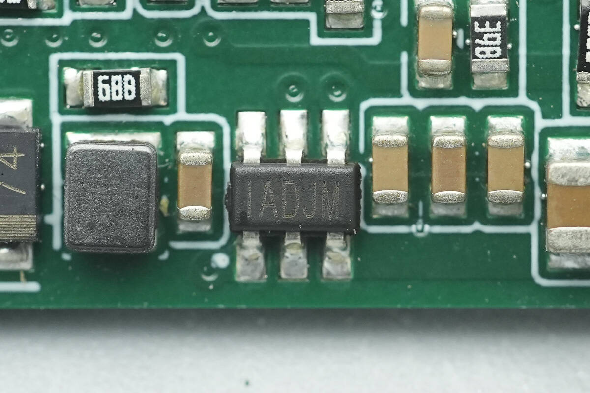
The buck converter is from MPS, marked “IADJ,” model MP1470. It is a synchronous buck converter with a 16 V input rating and 2 A output current capability, featuring an integrated MOSFET and packaged in TSOT-23-6.
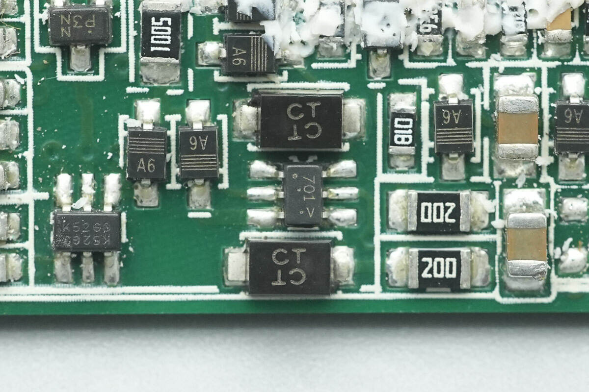
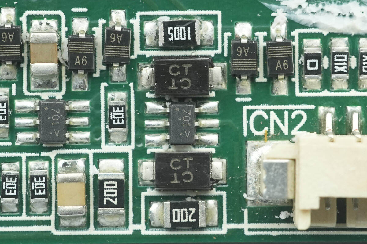
Two TVS diodes marked “CT” are used for overvoltage protection.
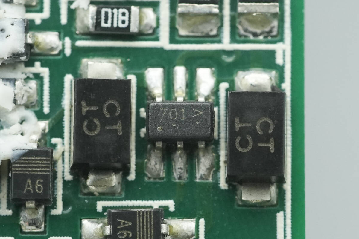
The small-signal MOSFET is from LRC, marked “701,” model L2N7002SDW1T1G. It is an N-channel MOSFET with a 60 V rating and comes in an SOT-363 package.
Close-up of another set of TVS diodes and MOSFETs.
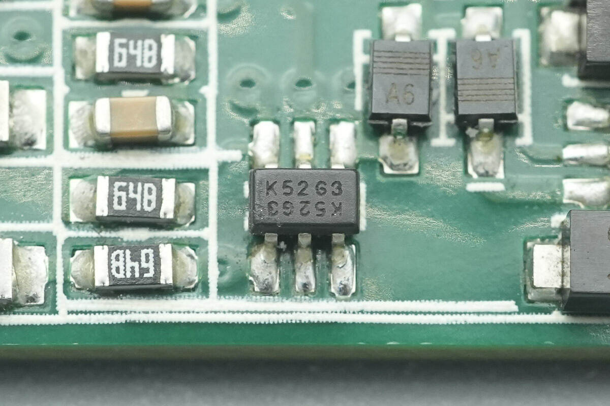
The diode is from DIODES, marked “K52,” model BAV199DW-7-F. It is rated at 60 V and comes in an SOT-363 package.
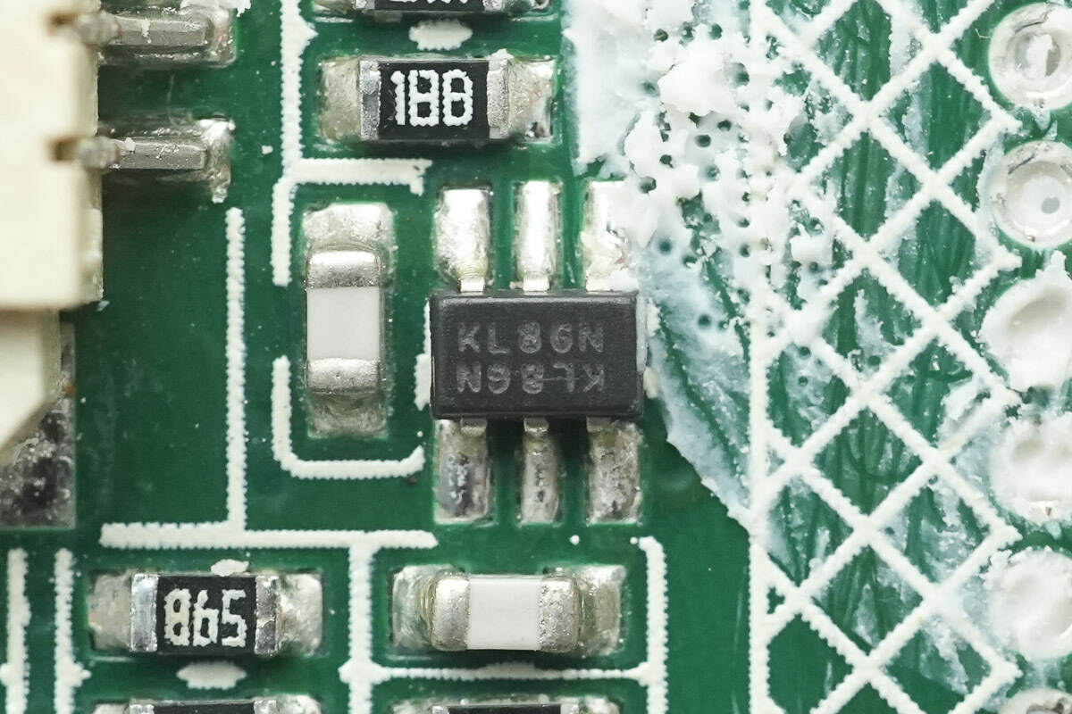
The Schottky diode array is from DIODES, marked “KL8,” model BAT54SDW. It is rated at 30 V and comes in an SOT-363 package.
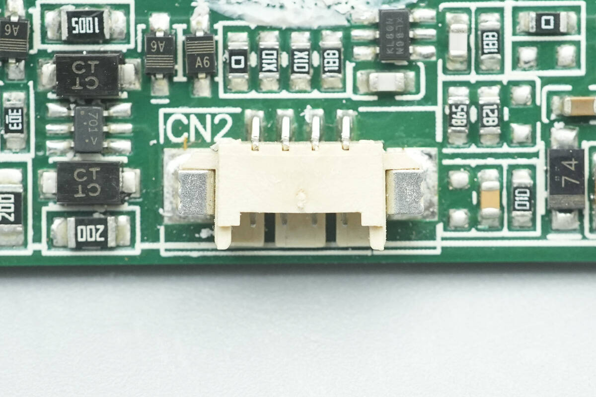
Close-up of the connector socket.
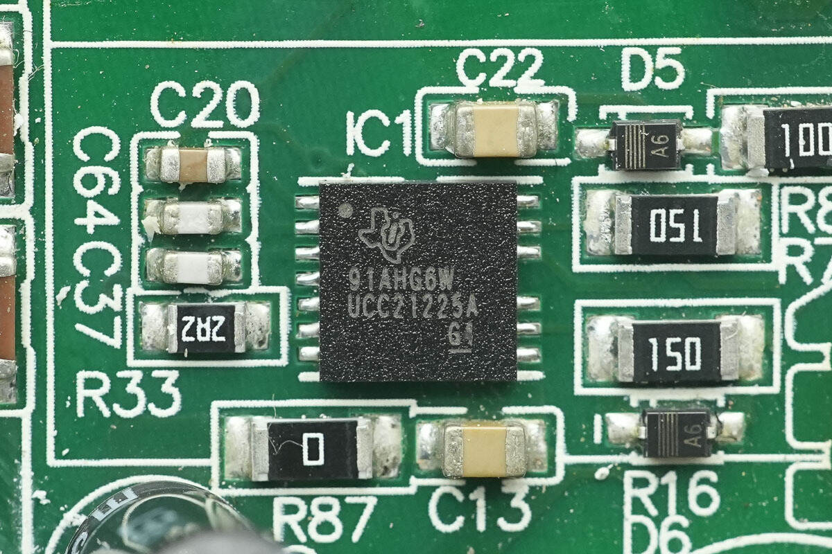
The isolated gate driver is from TI, model UCC21225A. It is a dual-input, dual-channel isolated gate driver supporting GaN, IGBT, MOSFET, and SiC applications, and comes in an LGA-13 package.
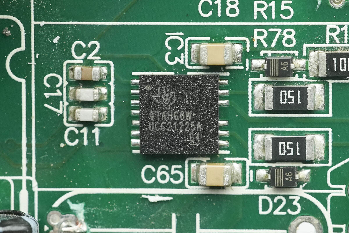
Another isolated gate driver with the same model is used to drive the dual PFC MOSFETs.
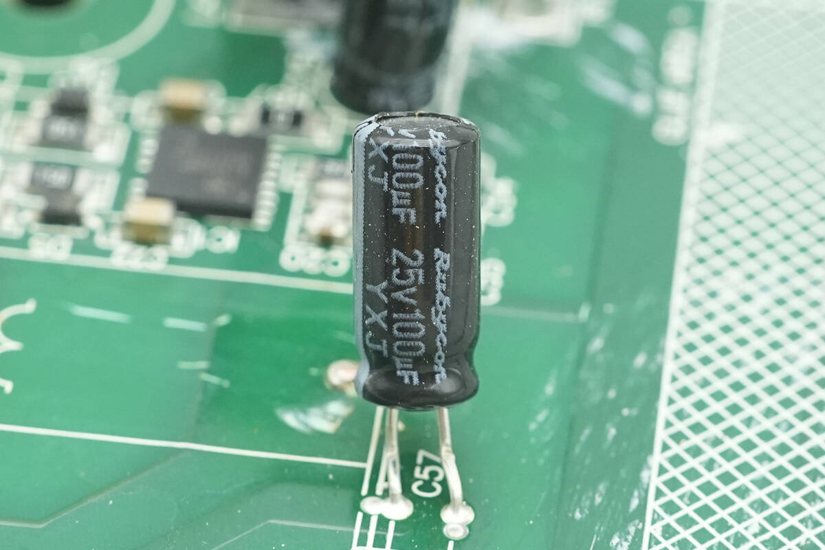
The filter capacitor is from Rubycon, rated at 25 V 100 μF.
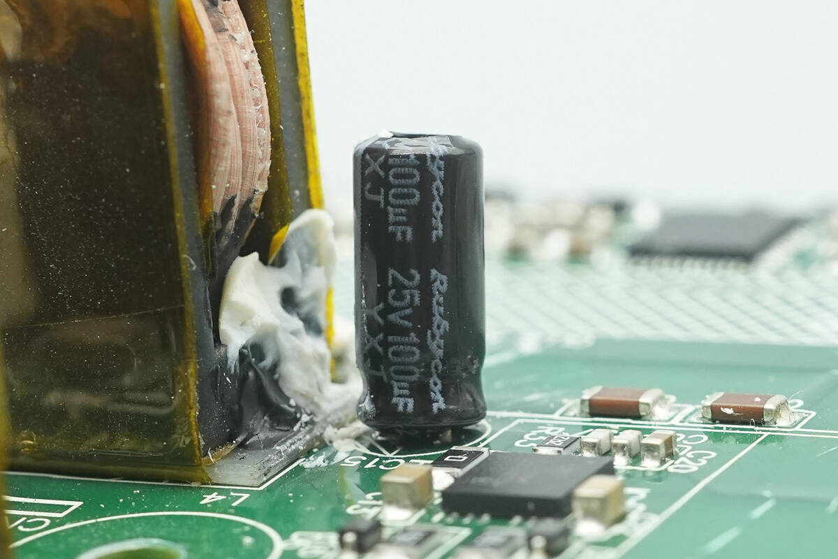
Another filter capacitor has the same rating.
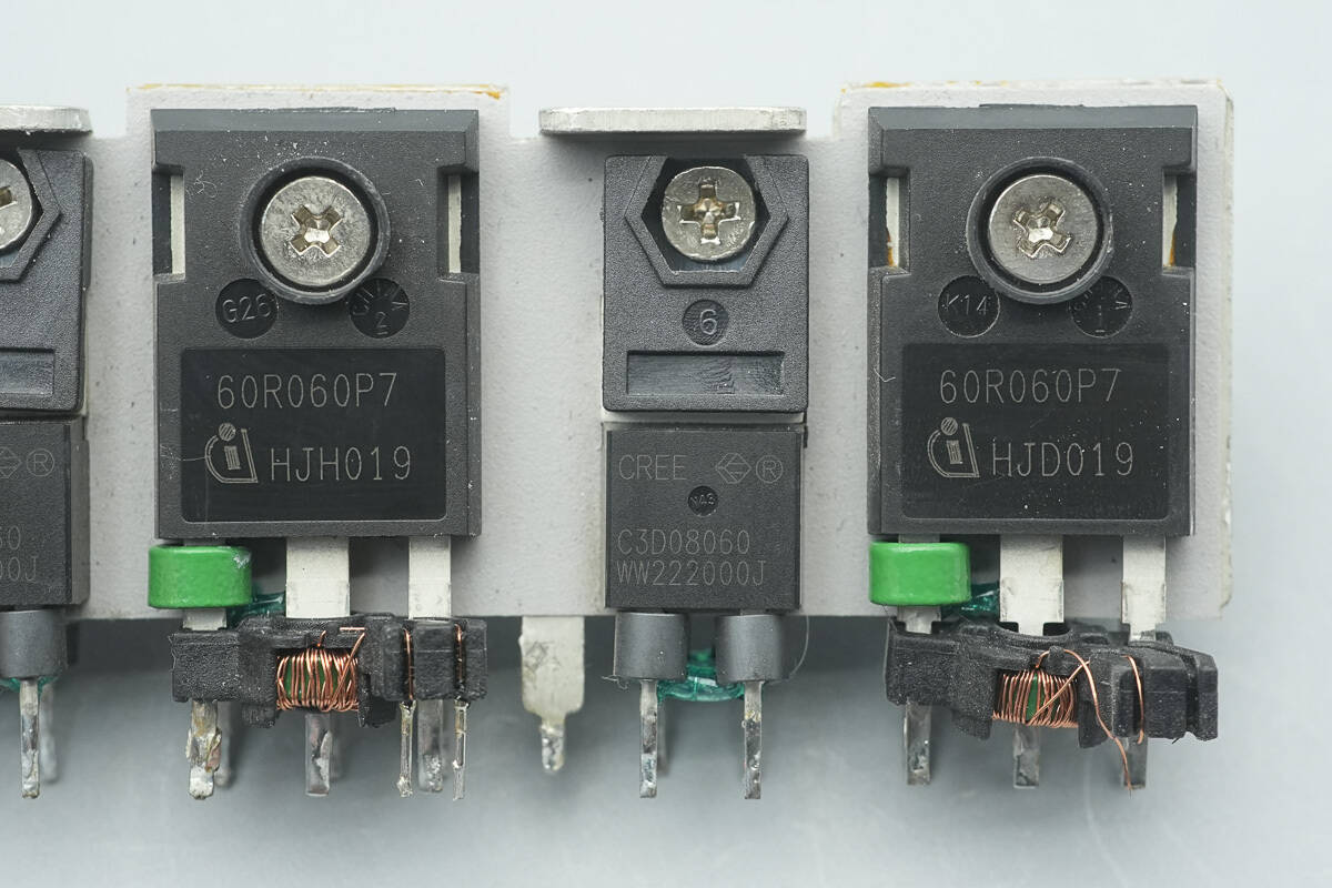
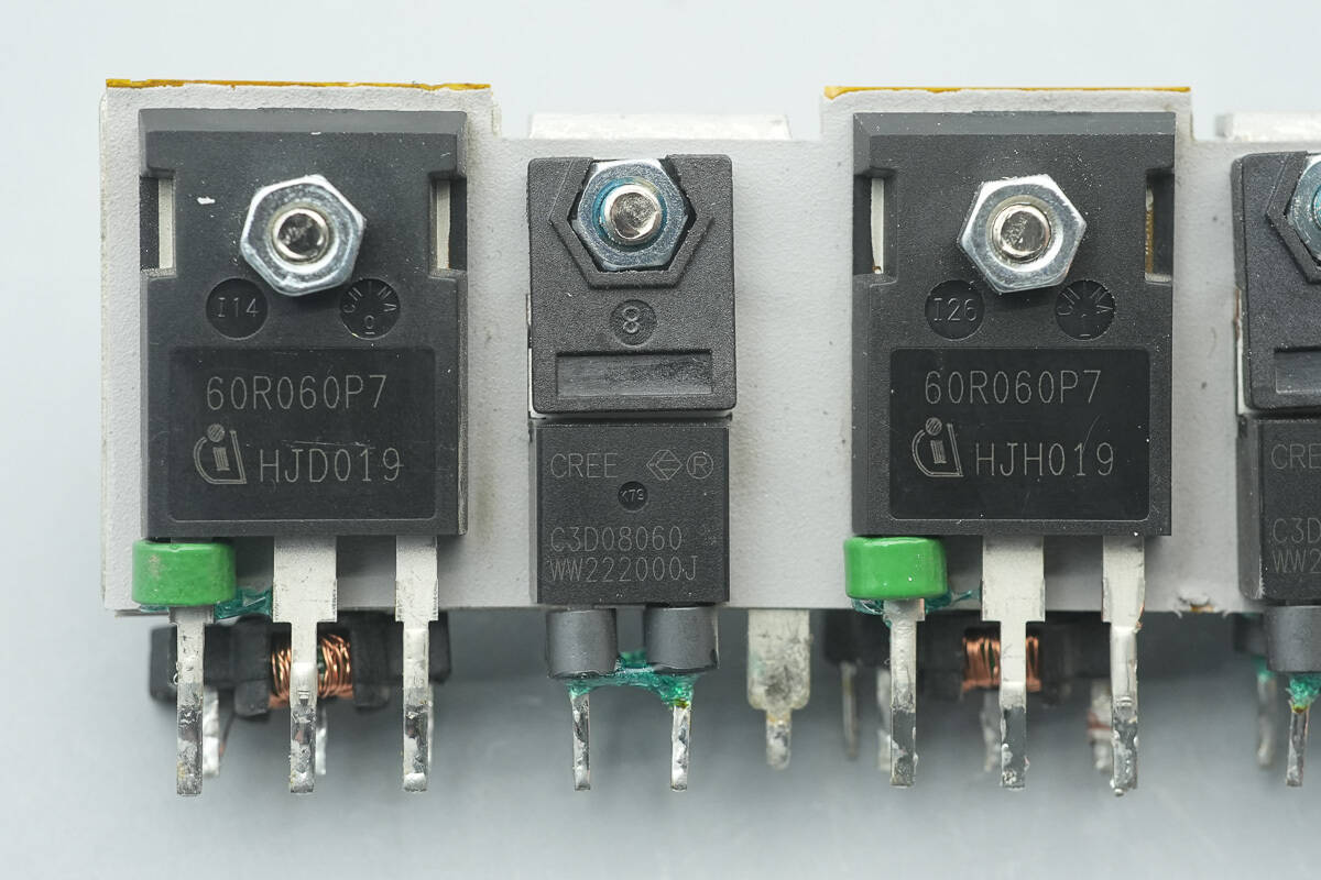
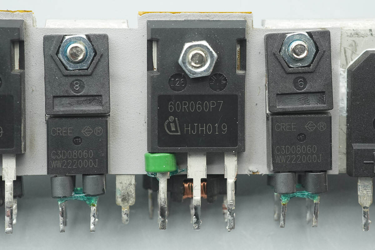
The PFC MOSFETs are from Infineon, marked “60R060P7,” model IPW60R060P7. They belong to the CoolMOS P7 series, are N-channel MOSFETs with a 650 V rating, 60 mΩ on-resistance, and come in a TO-247-3 package.
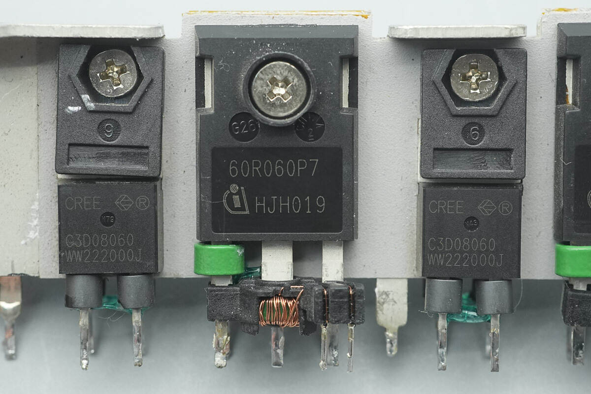
The SiC diode is from Wolfspeed, model C3D08060A, rated at 600 V/8 A, and comes in a TO-220-2 package.
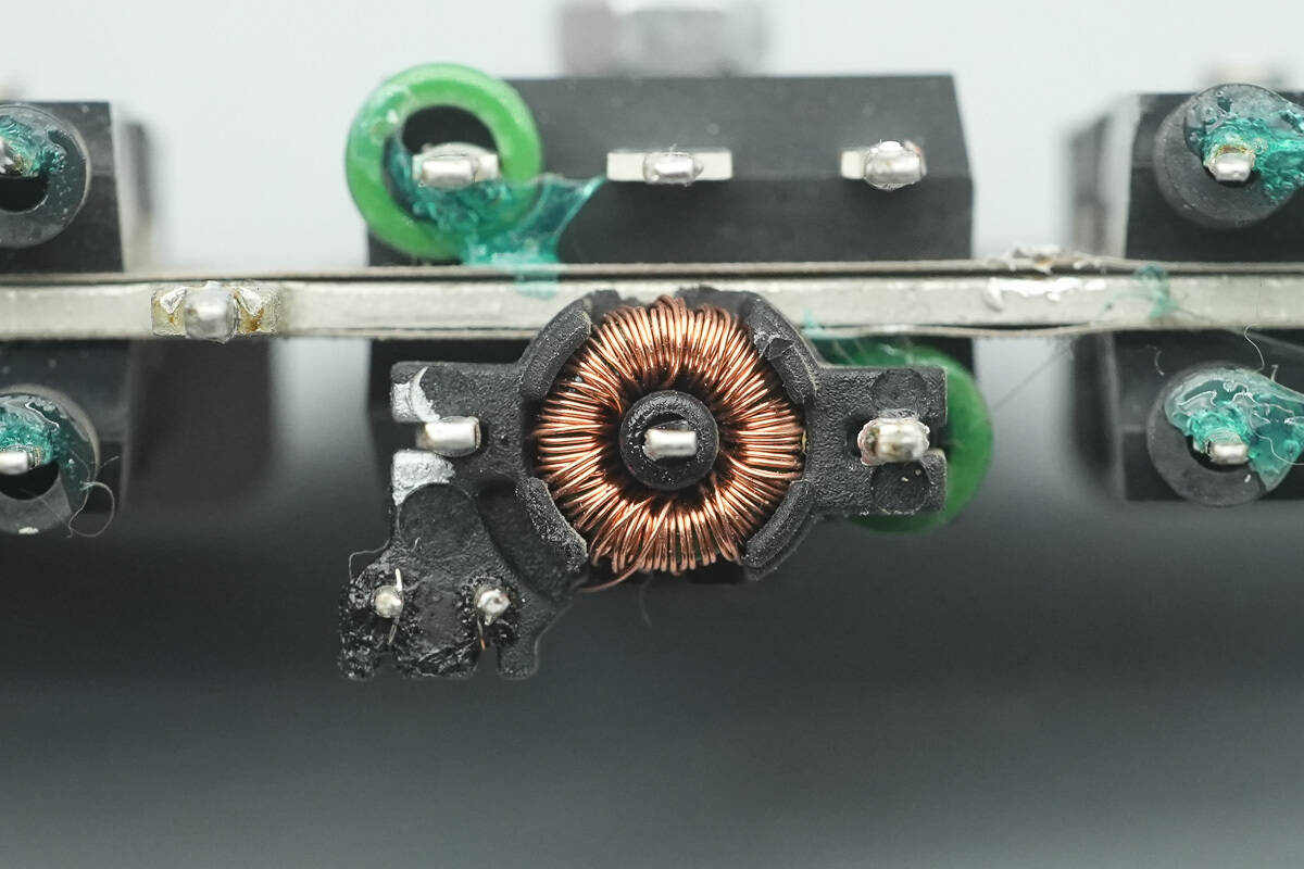
A current transformer is installed beneath the PFC MOSFET pins to monitor the switch current.
On the other side of the heatsink, there are two additional MOSFETs with the same model.
On the other side of the heatsink, there are two additional rectifiers of the same model.
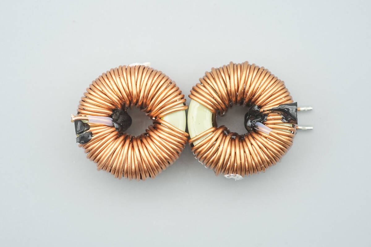
The PFC boost inductors are wound on magnetic cores.
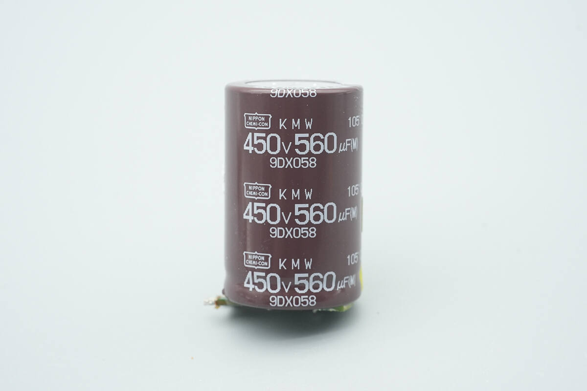
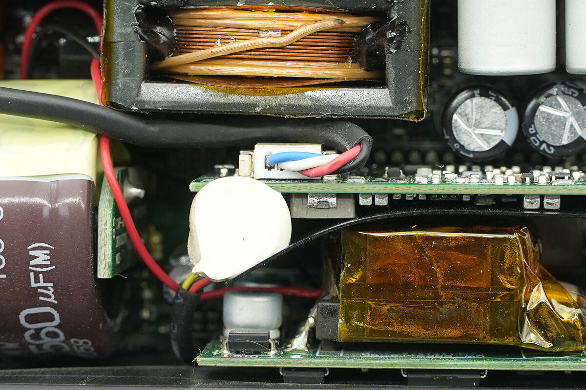
The filter capacitor is from NCC, part of the KMW series of compact electrolytic capacitors, rated at 450 V 560 μF.
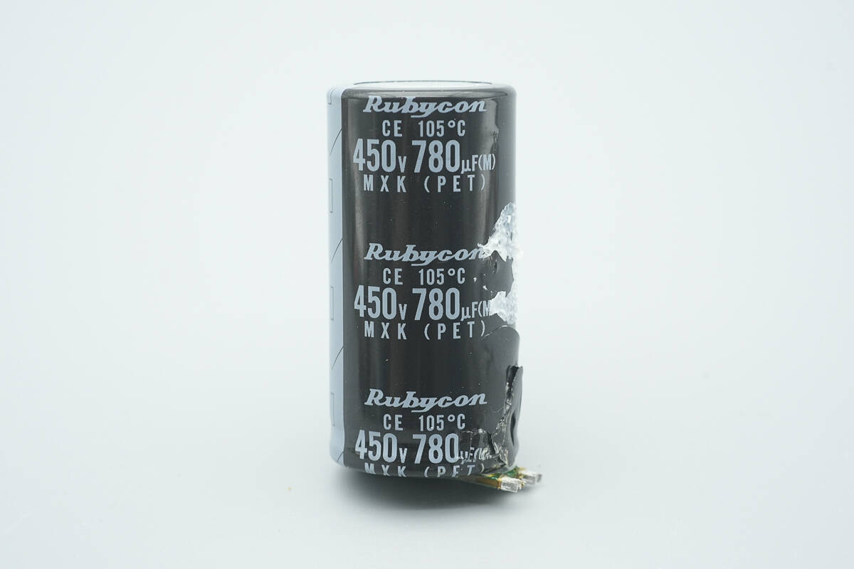
Another filter capacitor is from Rubycon, rated at 450 V 780 μF.

The film capacitor is from Nitsuko, part of the FPB series of compact capacitors, rated at 630 V 0.68 μF.
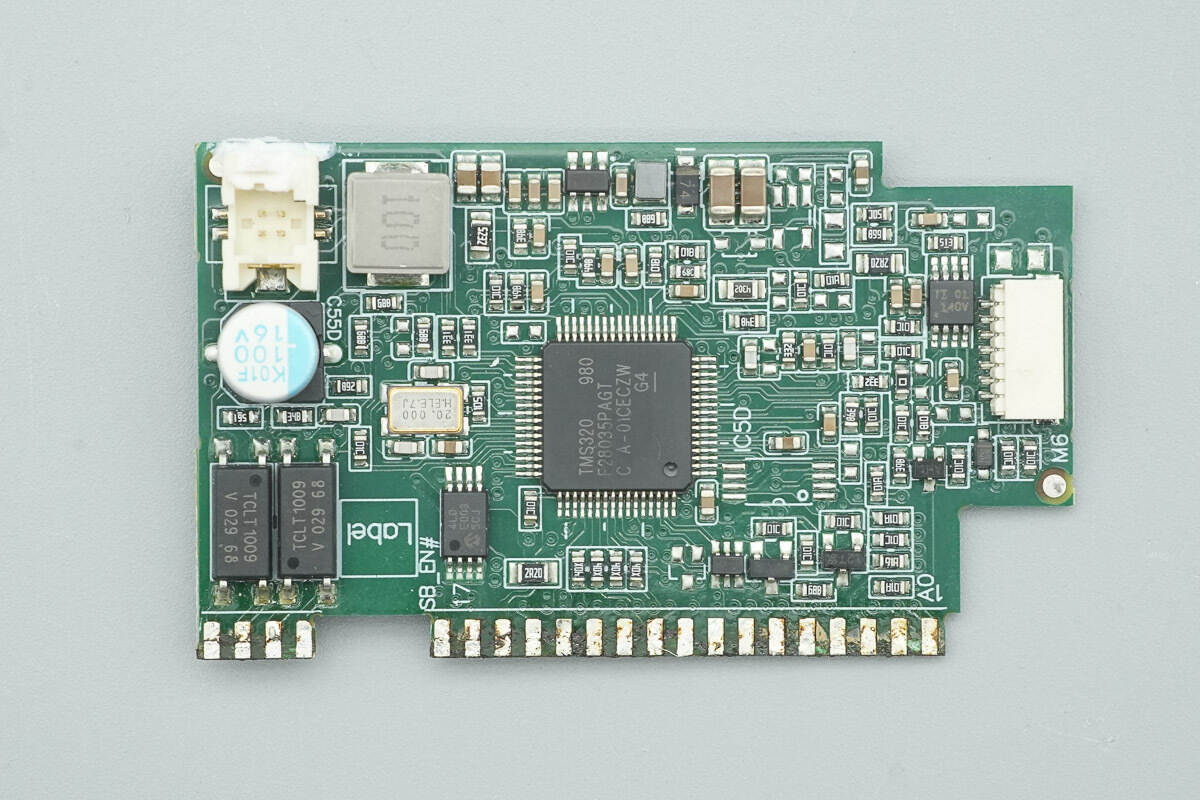
The front side of the LLC control PCB features the LLC controller, a crystal oscillator, memory, a buck converter, an operational amplifier, a filter capacitor, and isolated optocouplers.
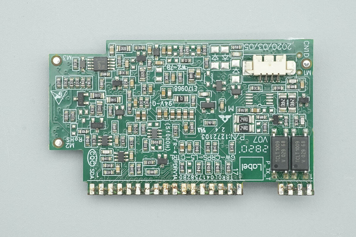
The rear side is equipped with operational amplifiers and feedback optocouplers.
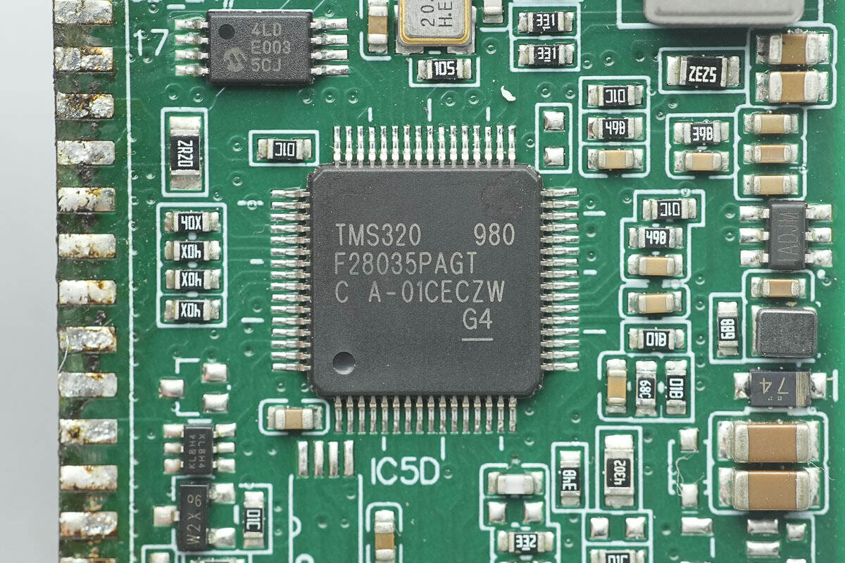
The LLC controller is from TI, part of the C2000 series of real-time microcontrollers, model TMS320F28035PAG. It features a 32-bit CPU core with a 60 MHz main frequency, supports coordinated computation, fast interrupt response and processing, and includes 128 KB of internal flash memory. It can be used in applications such as air conditioner outdoor units, DC-DC converters, inverters, motor control, onboard chargers (OBC), charging stations, and BLDC motor drivers. The chip comes in a TQFP-64 package.
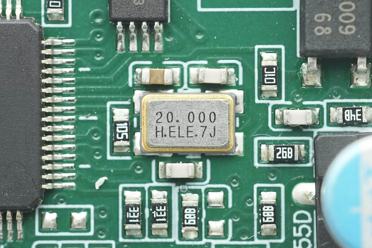
Close-up of the 20.000 MHz external clock crystal.
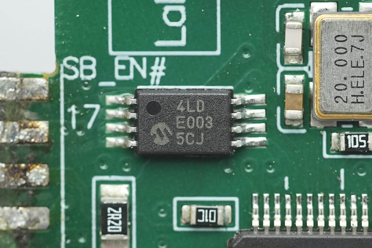
The memory is from Microchip, marked “4LD,” model 24LC256. It has a capacity of 256 KB, supports a 2.5–5.5 V operating voltage, and comes in an 8-lead TSSOP package.
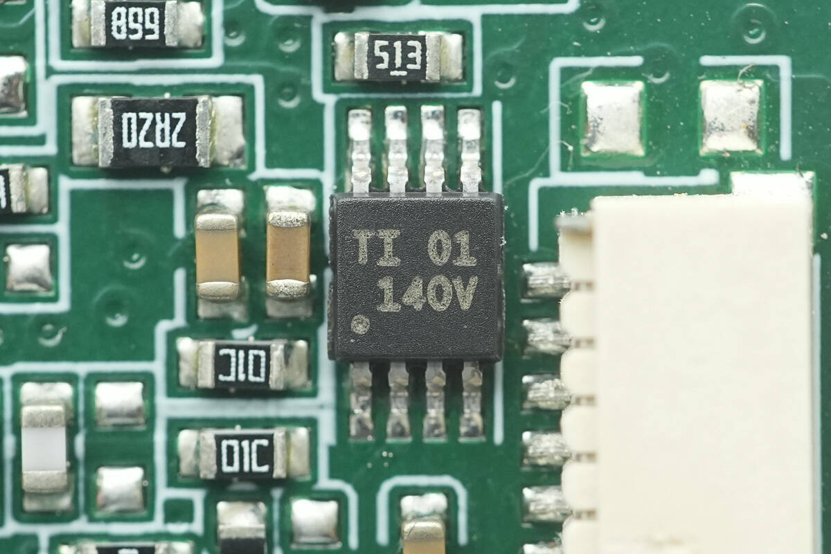
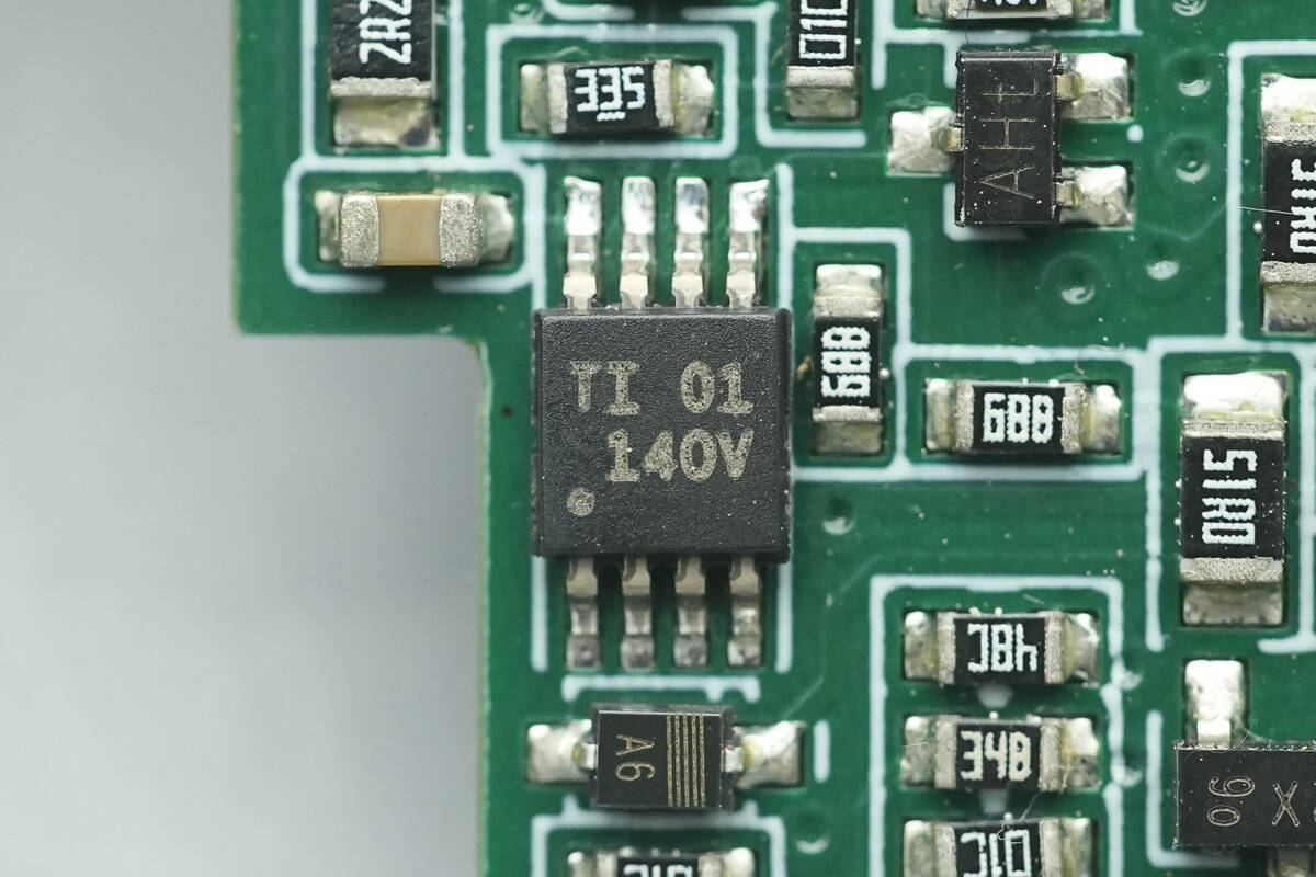
The operational amplifier is from TI, marked “14OV,” model TLV2171. It is a dual low-power op-amp, supports a 36 V operating voltage, and comes in a VSSOP-8 package.
Another operational amplifier with the same model is installed.
The buck converter uses the MPS MP1470.
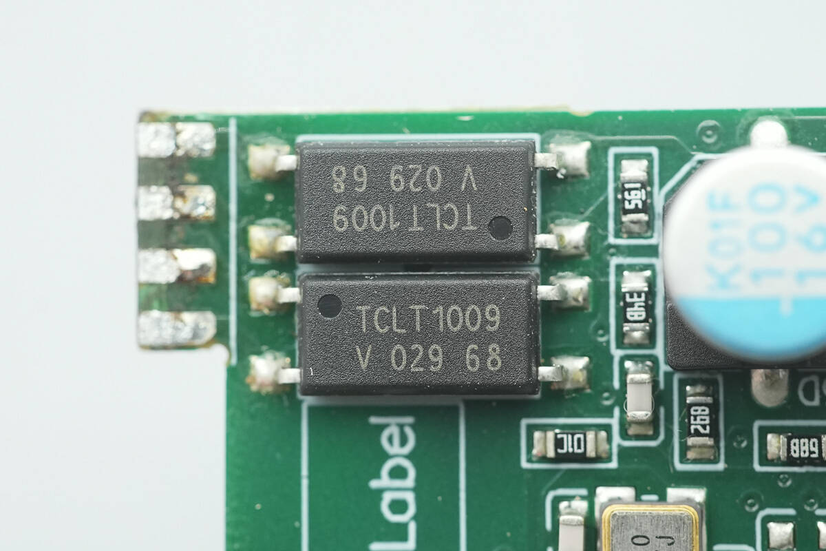
The isolated optocouplers are from VISHAY, model TCLT1009.
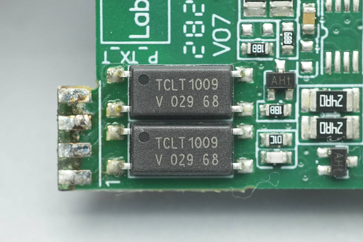
On the other side, there are two additional optocouplers of the same model.
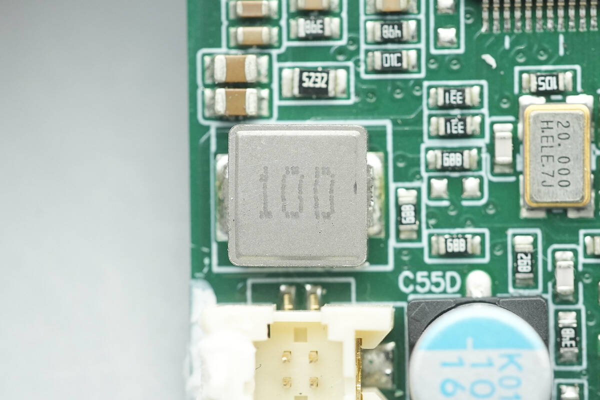
Close-up of the 10 μH SMD inductor.
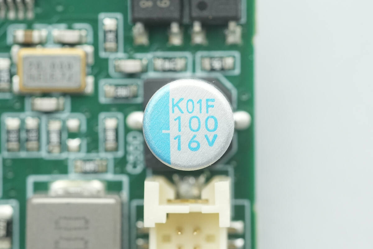
The filter capacitor is rated at 100 μF, 16 V.
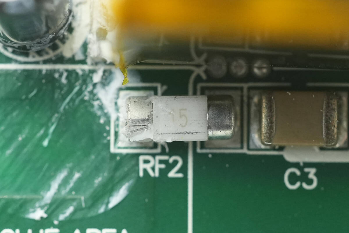
The SMD fuse is rated at 15 A.
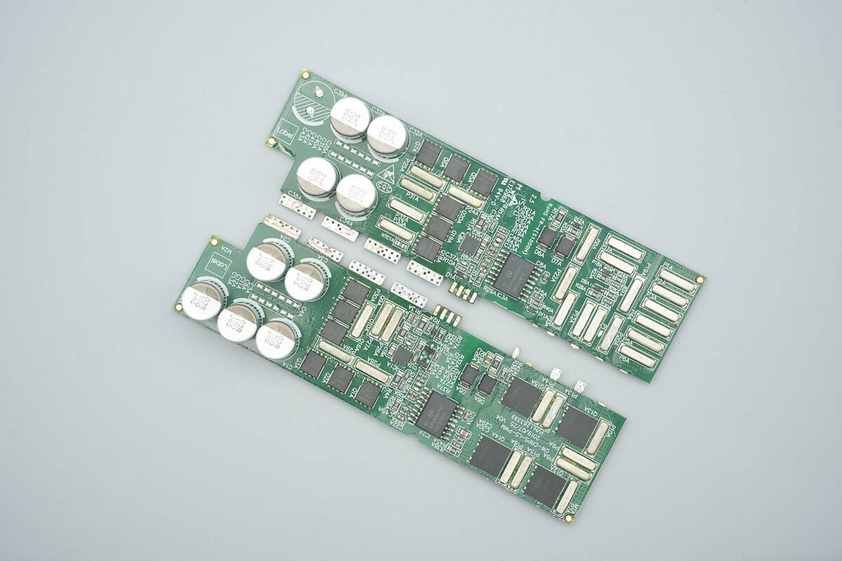
These two small PCBs feature filter capacitors, synchronous rectifiers, drivers, isolated gate drivers, and full-bridge LLC MOSFETs.
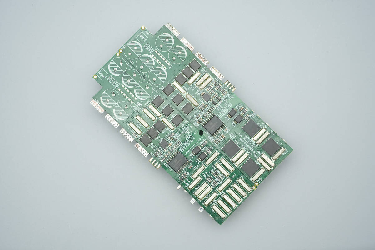
On one of the PCBs, the full-bridge LLC MOSFETs are soldered on the opposite side, while both sides feature synchronous rectifiers and isolated gate drivers.
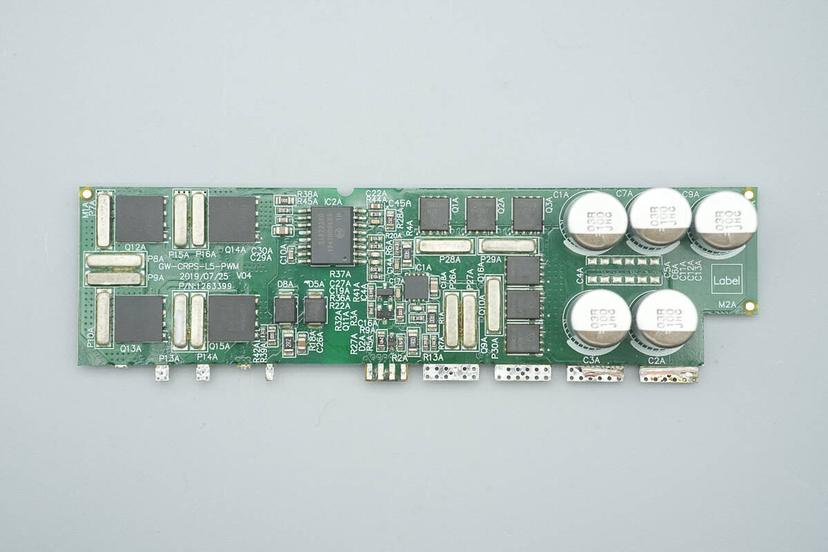
The front side of the small PCB is equipped with LLC MOSFETs, an isolated driver, ultra-fast recovery diodes, synchronous rectifiers, drivers, and filter capacitors.
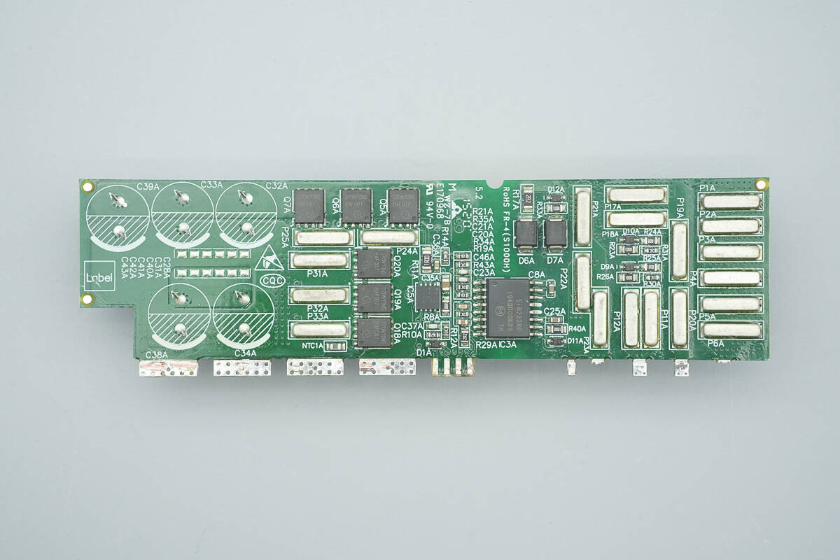
The other side is equipped with synchronous rectifiers, a driver, and isolated drivers.
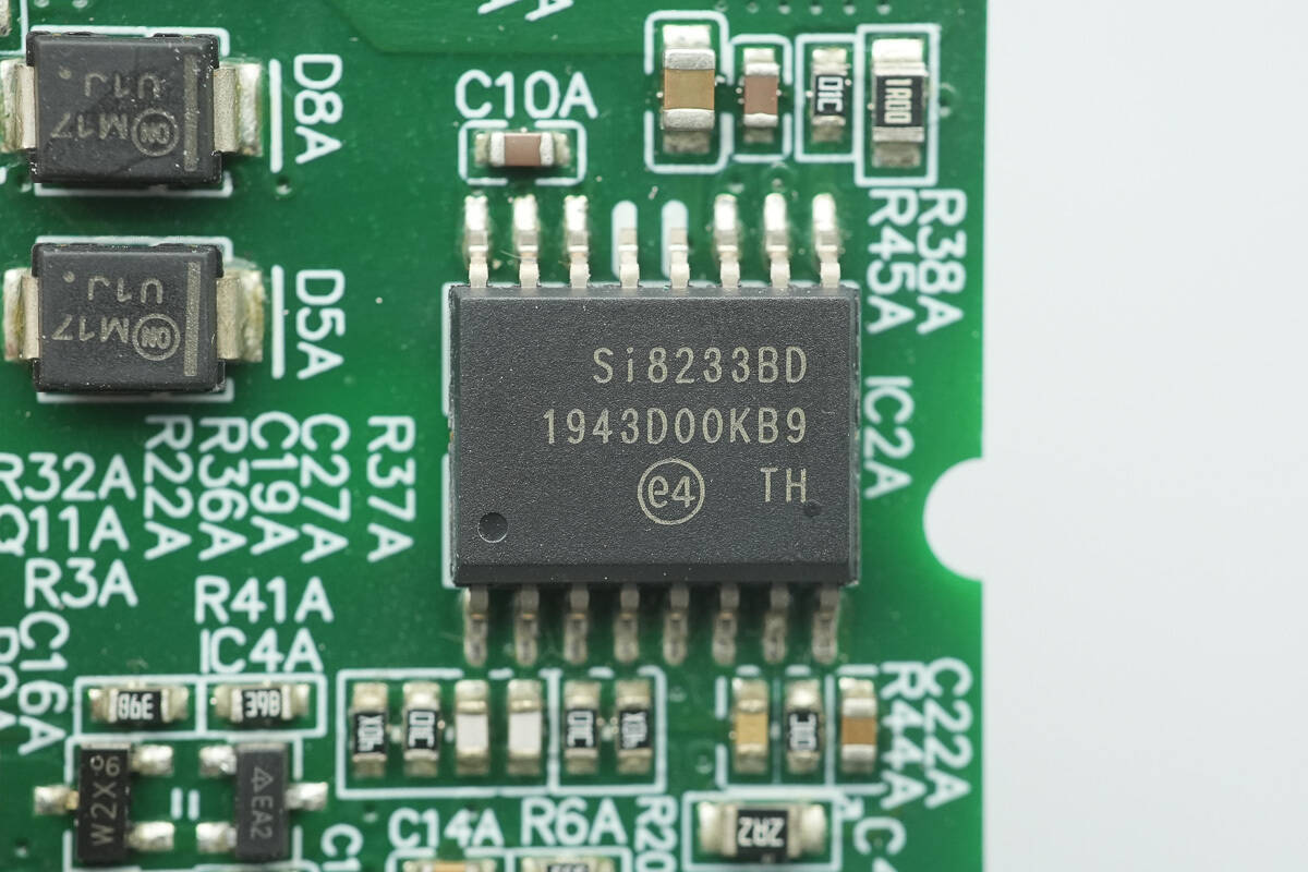
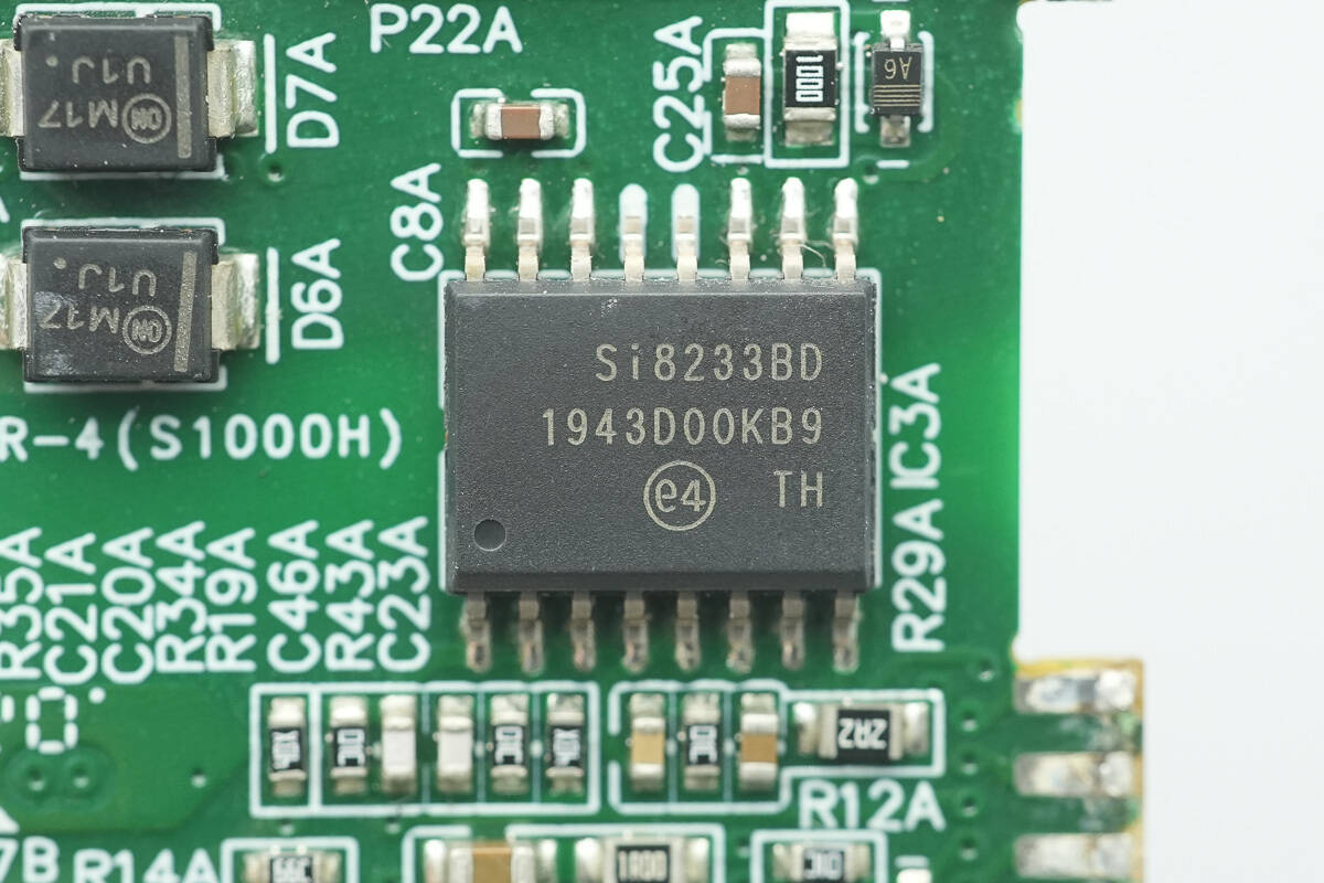
The isolated driver is from SKYWORKS, model Si8233BD. It is a high-side/low-side driver with a 4 A drive capability, supports a 24 V supply voltage, complies with UL1577 certification, provides 5 kV rms isolation, and comes in an SOIC-16WB package.
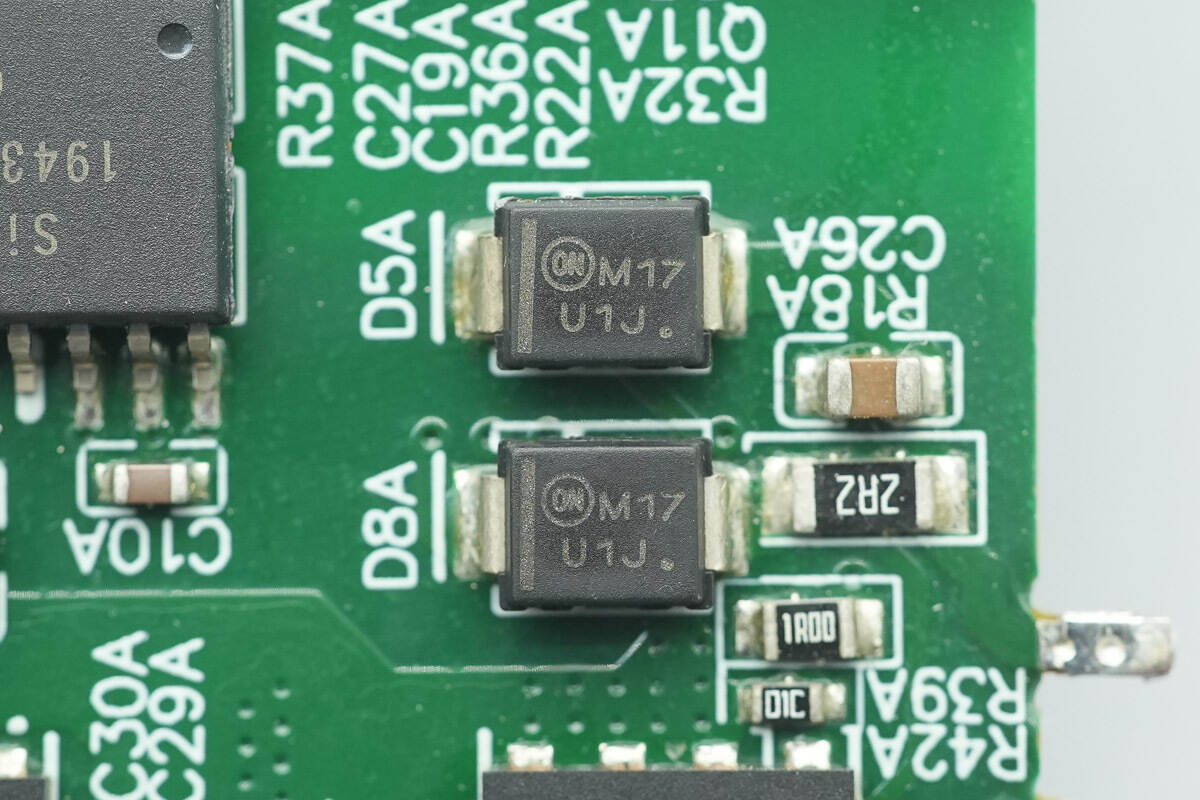
The two ultra-fast recovery diodes are from Onsemi, marked U1J, model MURS160. They are rated at 600 V, 1 A, and come in an SMB package.
The isolated driver on the other side is of the same model.
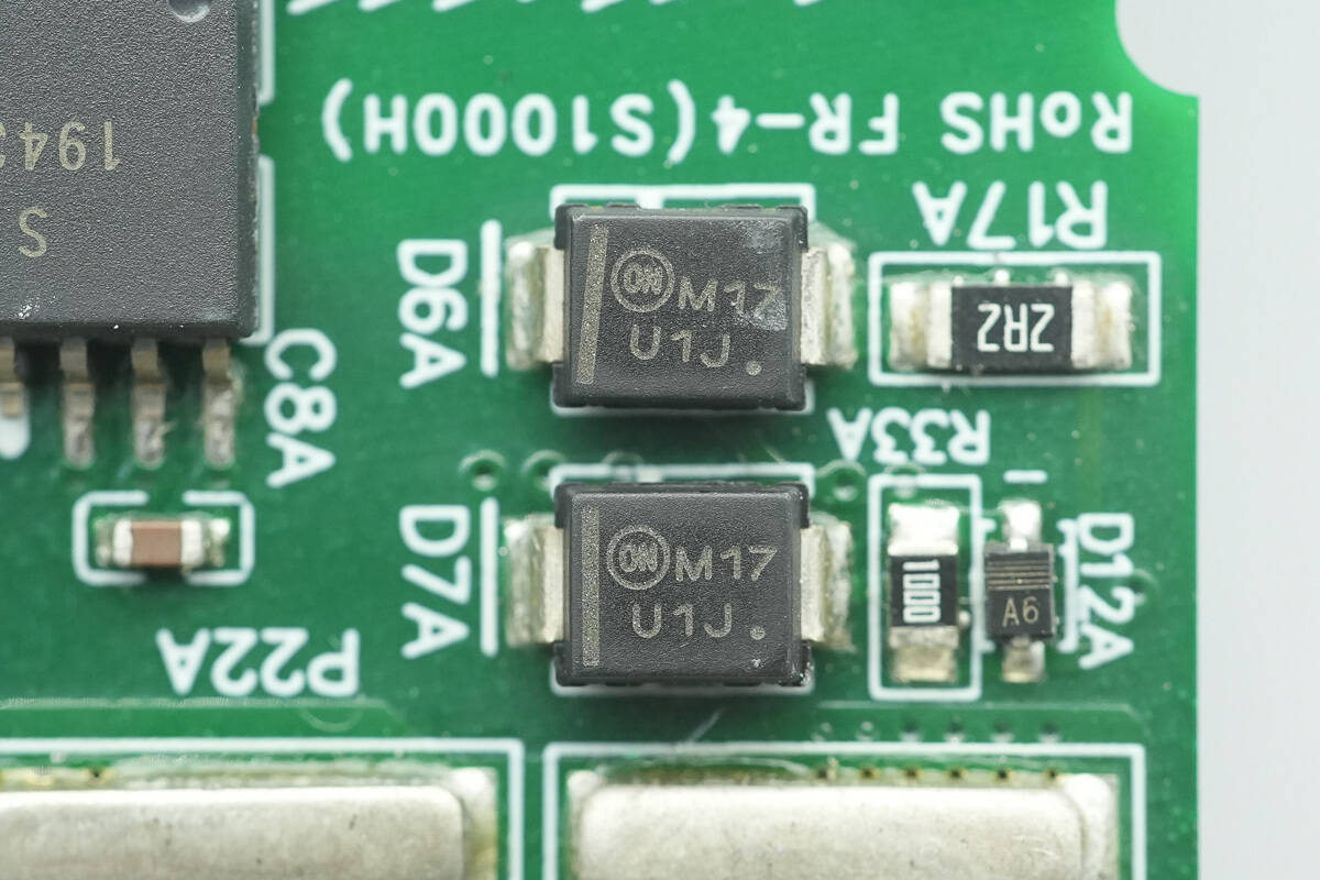
The other side has two ultra-fast recovery diodes of the same model.
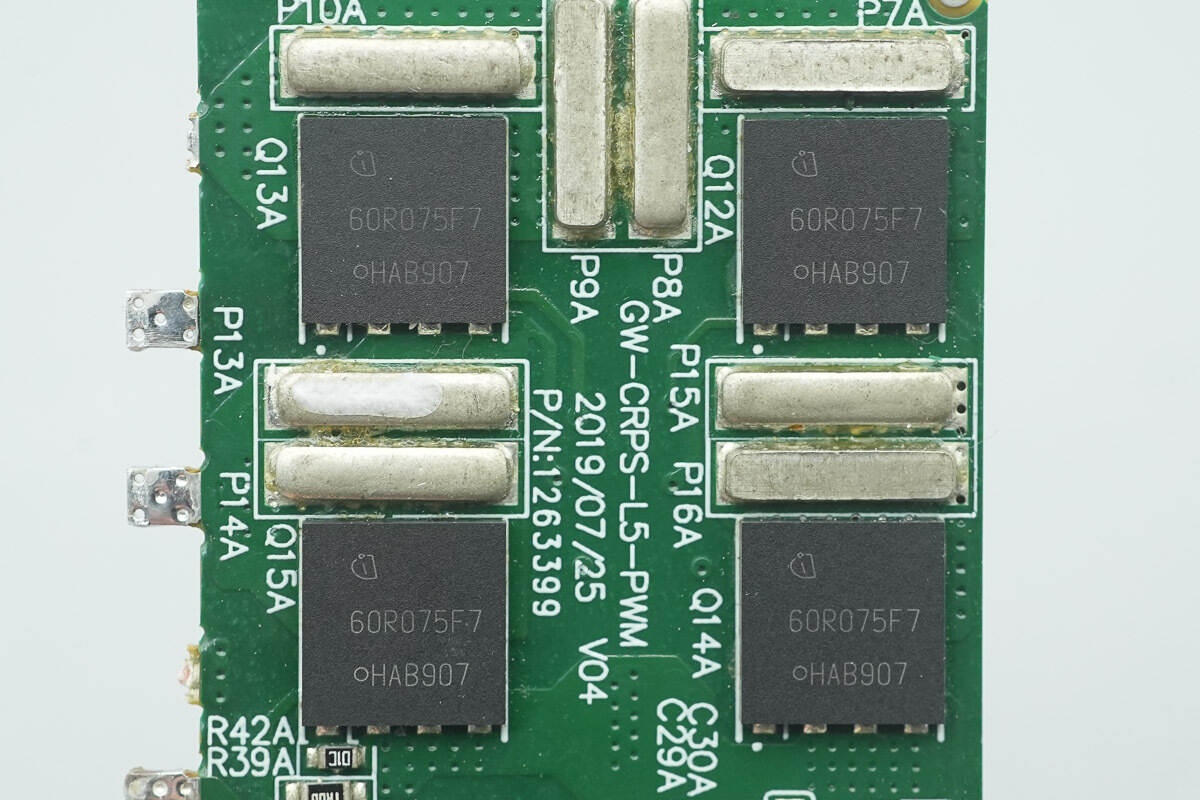
The full-bridge LLC MOSFETs are from Infineon, marked 60R075F7, model IPL60R075CFD7. They belong to the CoolMOS CFD7 series, are NMOS, rated at 650 V, with an on-resistance of 75 mΩ, and come in a VSON-4 package.
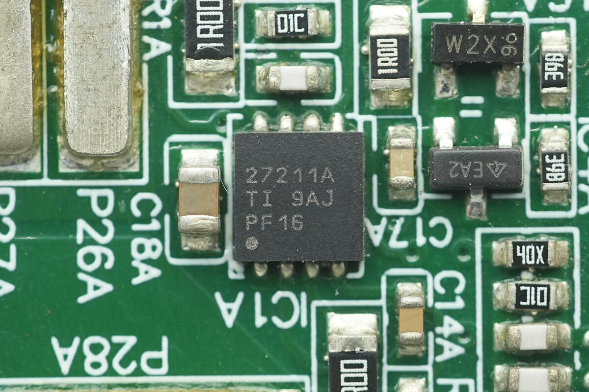
The driver is from TI, model UCC27211A. It is an automotive-grade 120 V driver with 3.7 A source current and 4.5 A sink current, and comes in an SON-8 package.
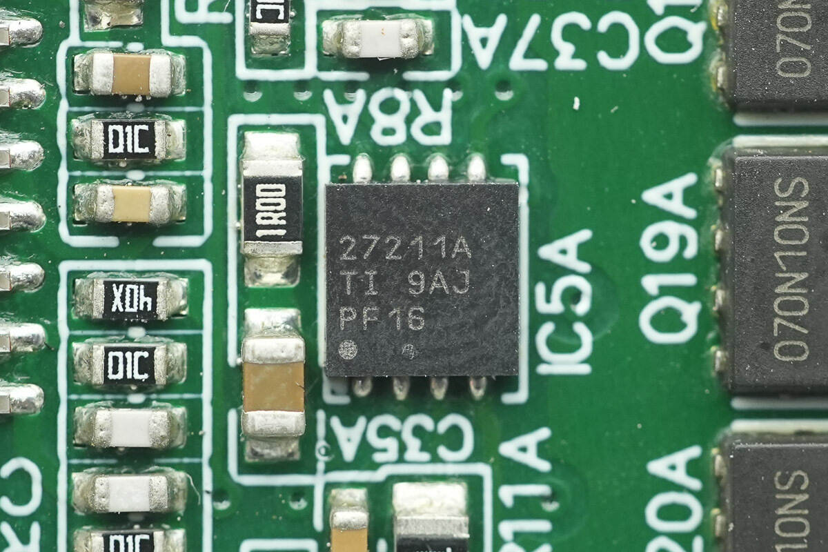
The other driver is of the same model.
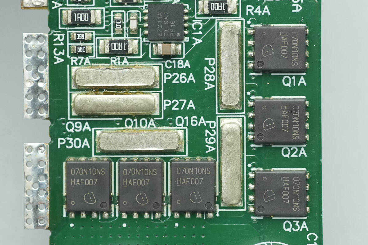
The synchronous rectifiers are from Infineon, model BSC070N10NS3G. They are NMOS, rated at 100 V, with an on-resistance of 7 mΩ, and come in a TDSON-8 package.
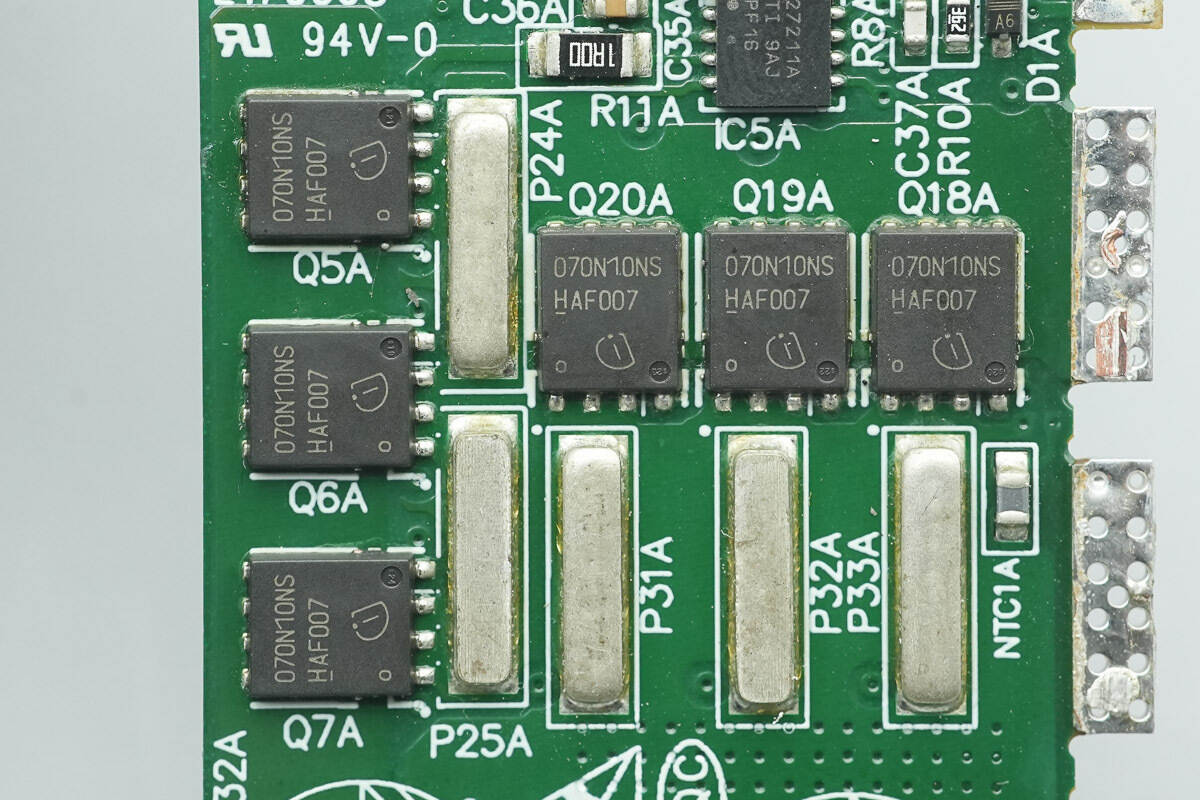
The other side has six synchronous rectifiers of the same model.
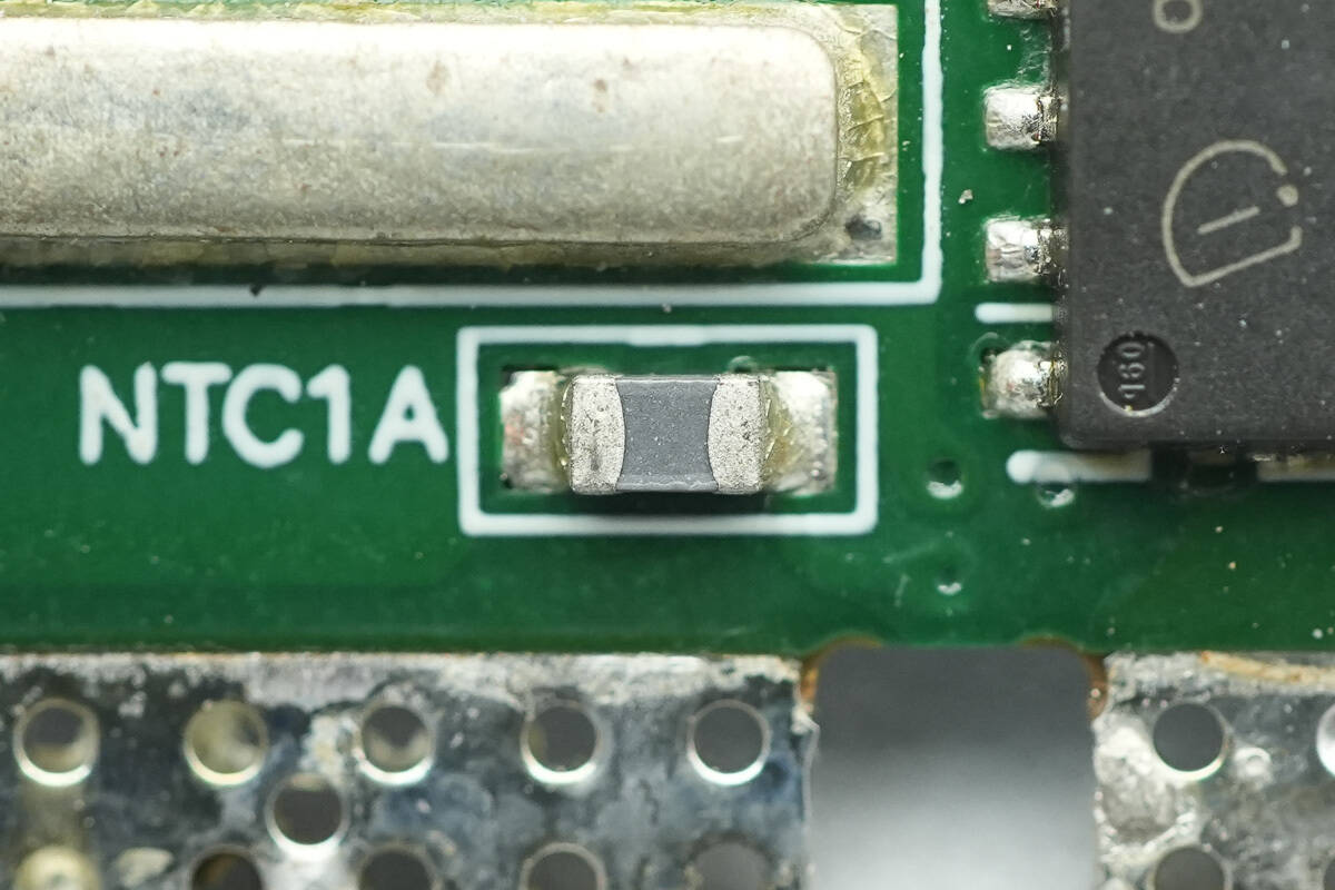
An NTC thermistor is used for temperature sensing.
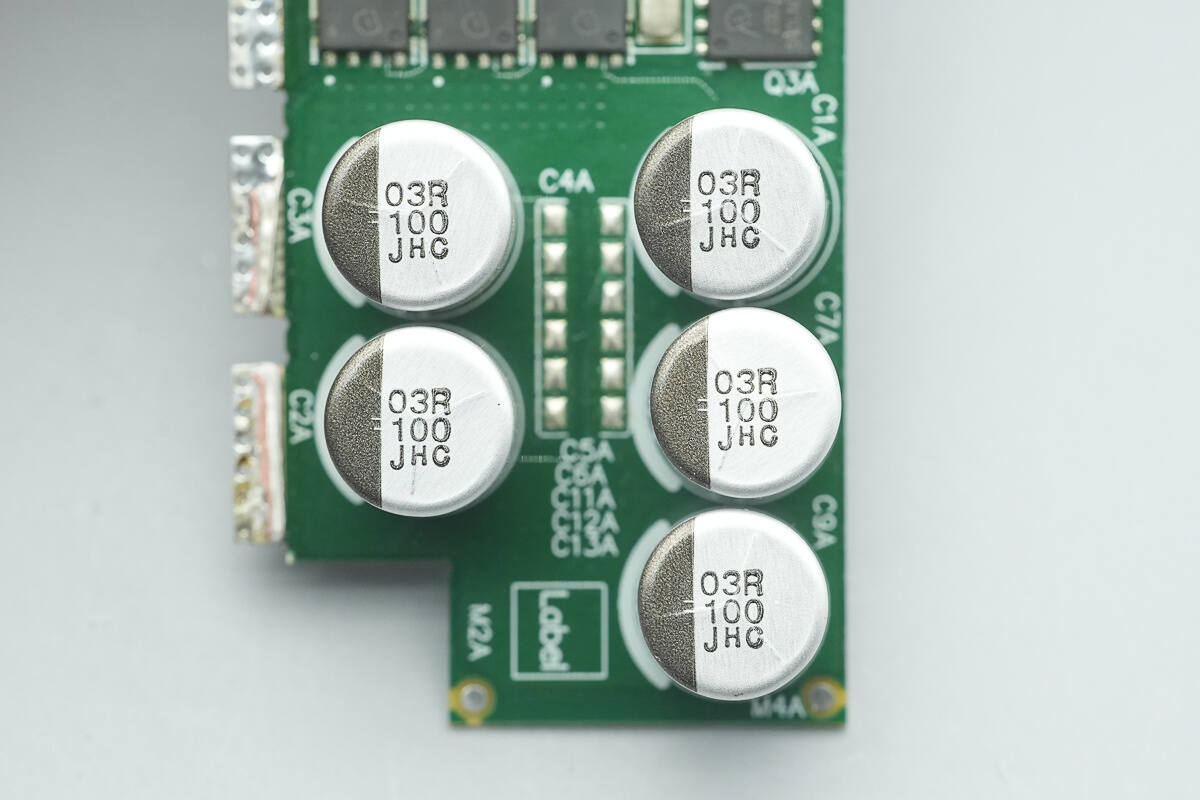
The output filter capacitors are from NCC, HSC series conductive polymer hybrid aluminum electrolytic capacitors, rated for 125 °C, with a lifespan of 4000 hours, and a specification of 100 μF 63 V.
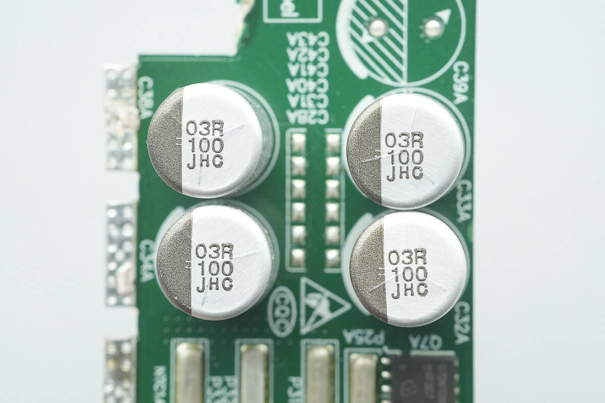
The other PCB has four filter capacitors; all other components are identical and will not be repeated here for brevity.
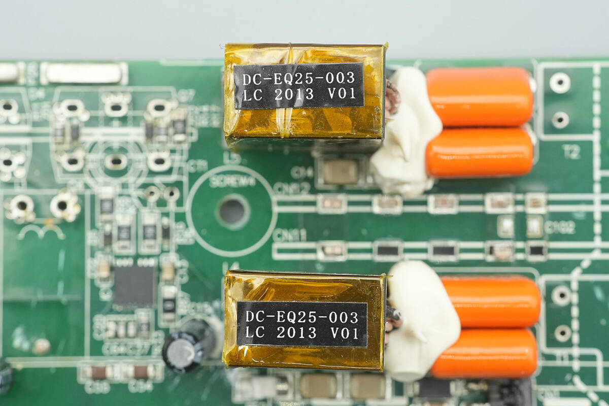
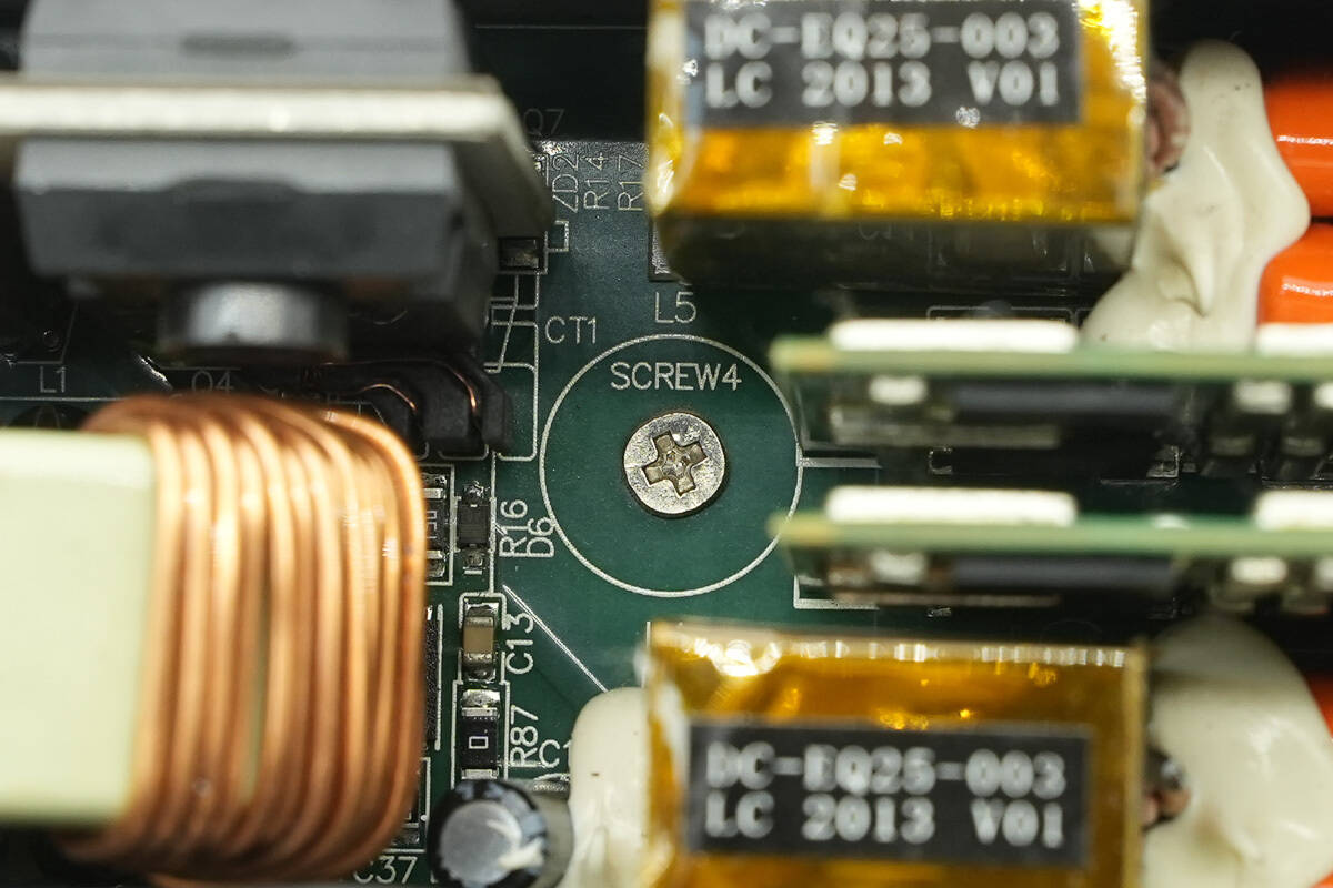
The resonant inductors are wound with Litz wire, and the EQ25 cores are insulated with high-temperature adhesive tape.
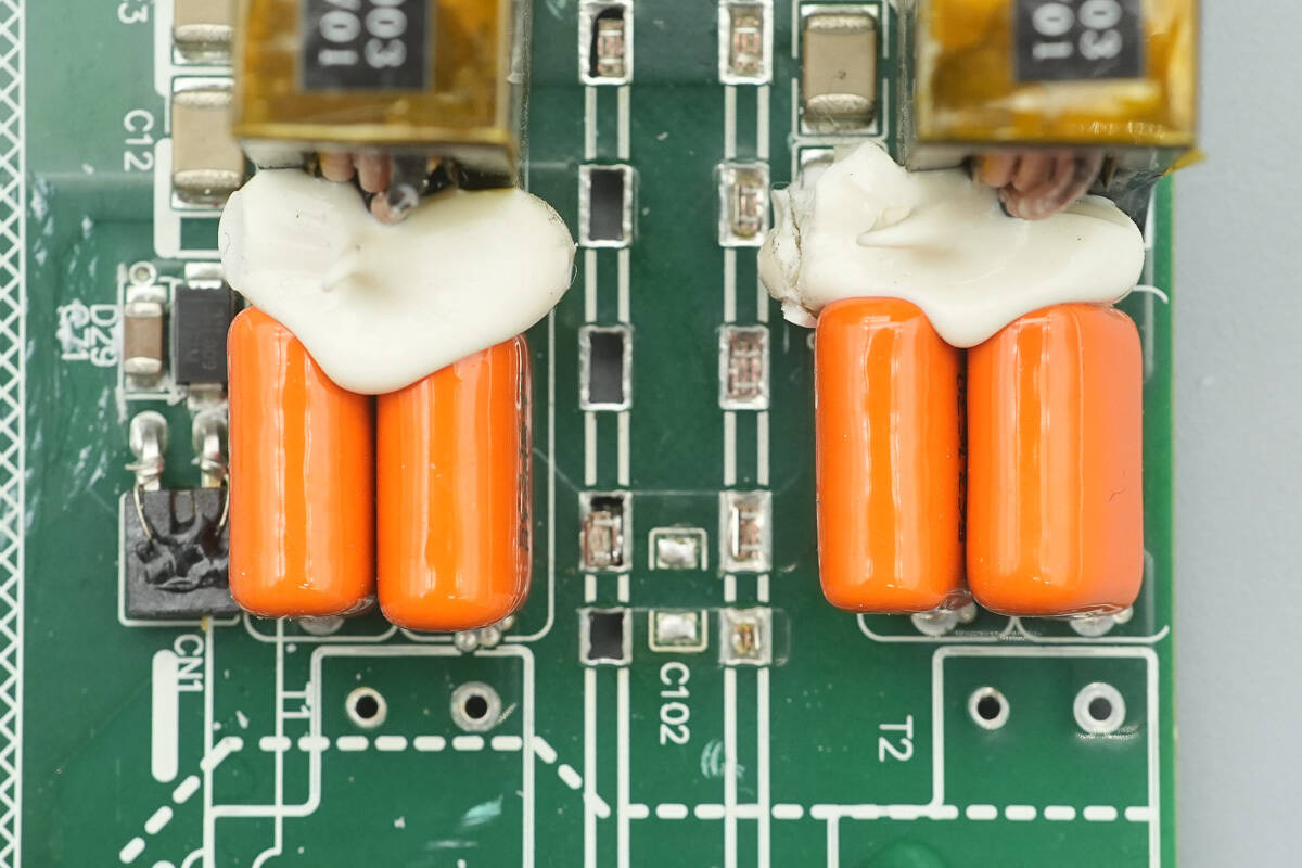
The two resonant capacitors are connected in parallel and reinforced with adhesive.
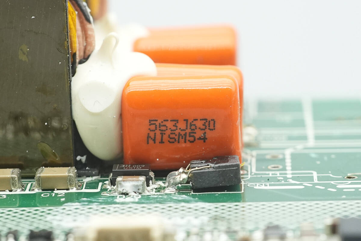
The resonant capacitors are rated at 0.056 μF, 630 V.
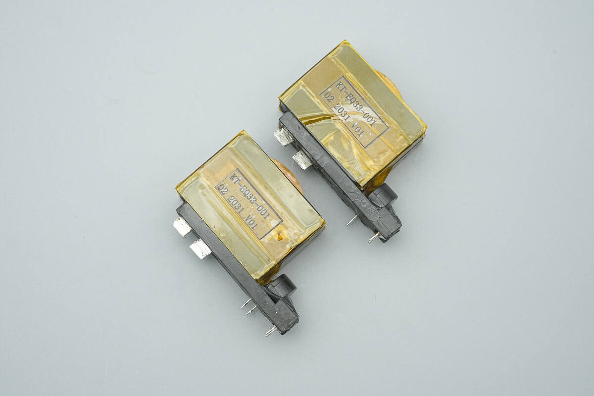
The two transformers are identical.
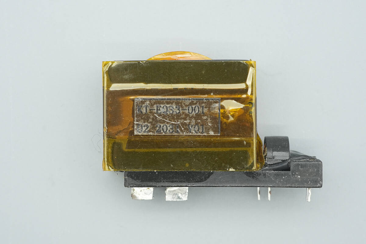
The transformer cores are insulated with winding tape.
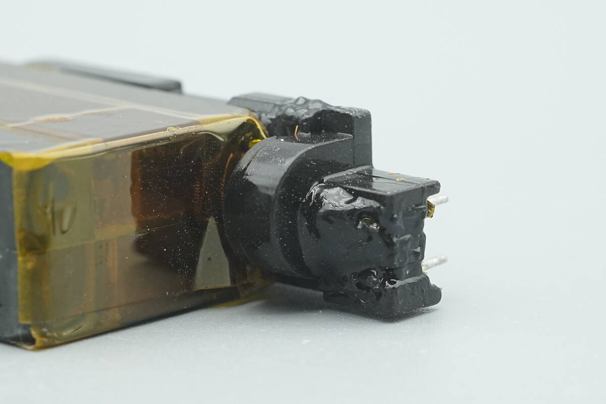
A current transformer is installed at the input of the transformer.
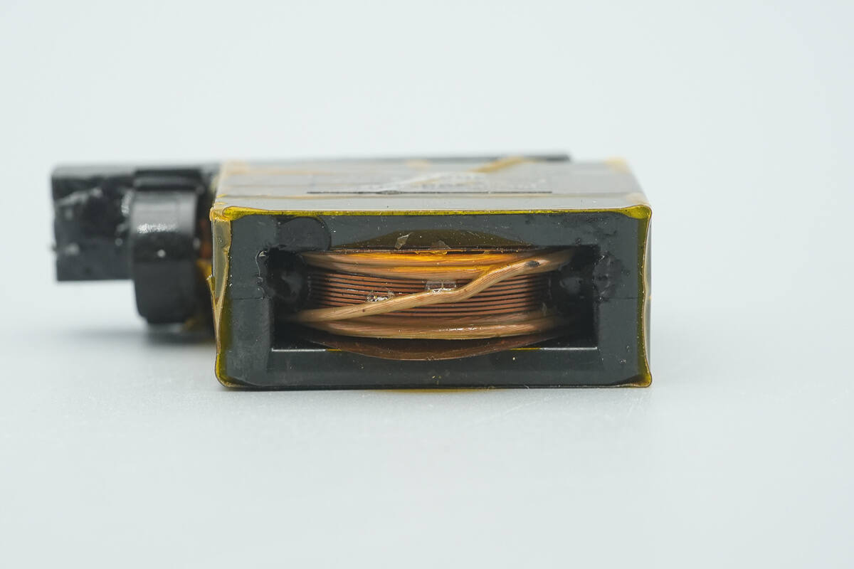
The transformer primary winding is wound with insulated wire, while the secondary winding is wound with copper foil.
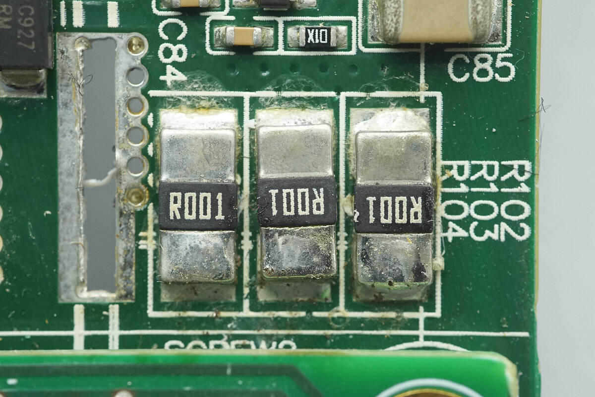
Three 1 mΩ resistors are connected in parallel to sense the output current.
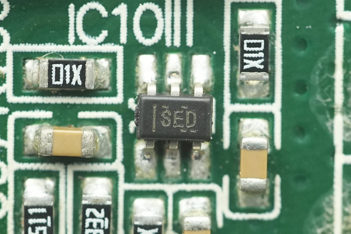
The current sensing chip is from TI, marked with SED, model INA210. It is a bidirectional high-precision current sense amplifier, and comes in an SC70 package.
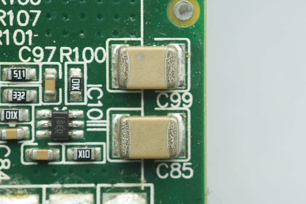
Two MLCCs are used for output filtering.
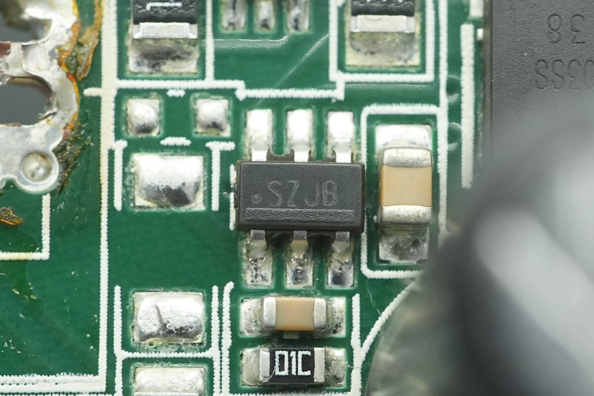
The ideal diode controller is from TI, marked with SZJB, model LM5050-2. It is a high-side controller, supporting a 6-75 V operating voltage, with a transient voltage tolerance of 100 V, and comes in an SOT23-6 package.
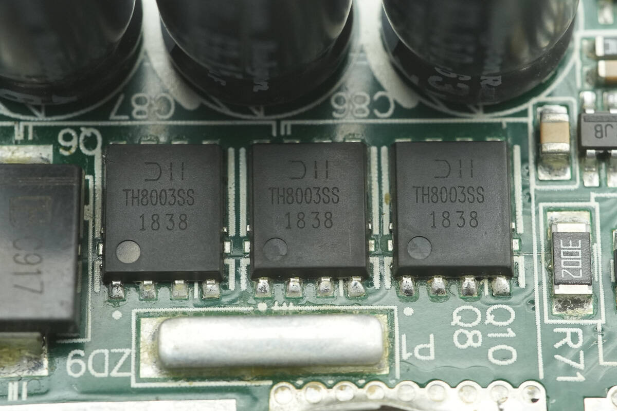
The output control MOSFETs are from DIODES, model DMTH8003SPS. They are NMOS, rated at 80 V, with an on-resistance of 3.9 mΩ, and come in a PowerDI5060-8 package.
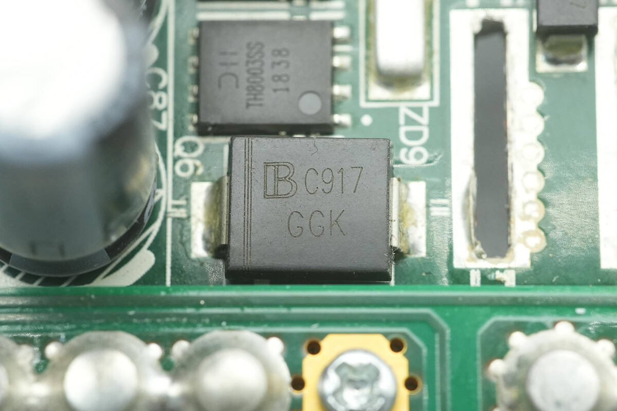
The TVS diode is from BrightKing, marked with GGK, model SMCJ60A. It has a reverse standoff voltage of 60 V and comes in an SMC package.
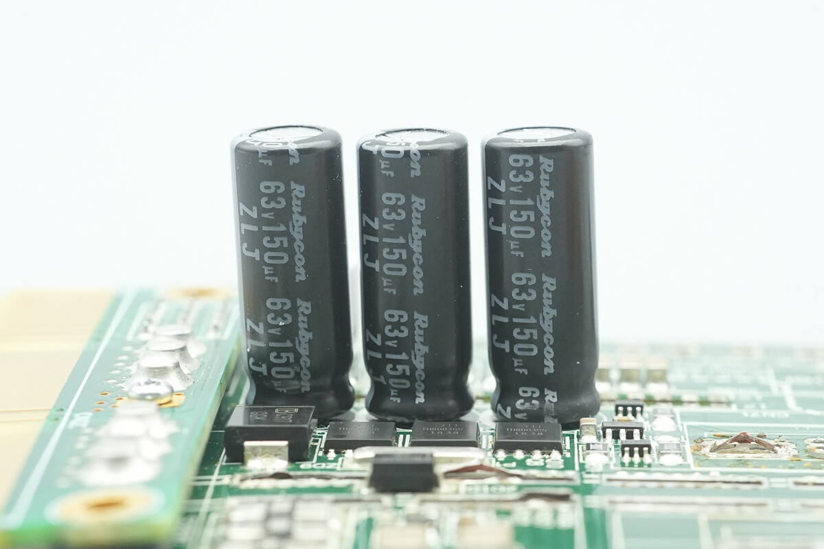
The output filter capacitors are from Rubycon, rated at 63 V, 150 μF.
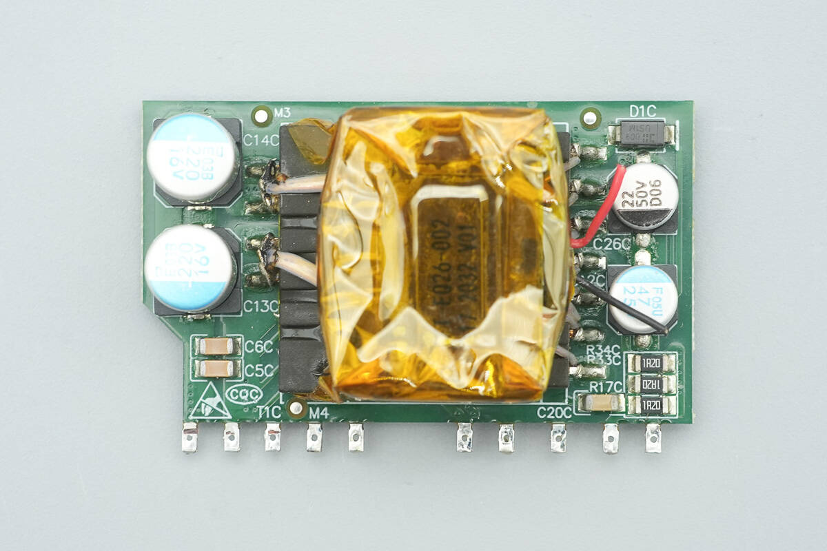
The standby power PCB has output filter capacitors on the left side, a transformer in the middle, and filter capacitors on the right side.
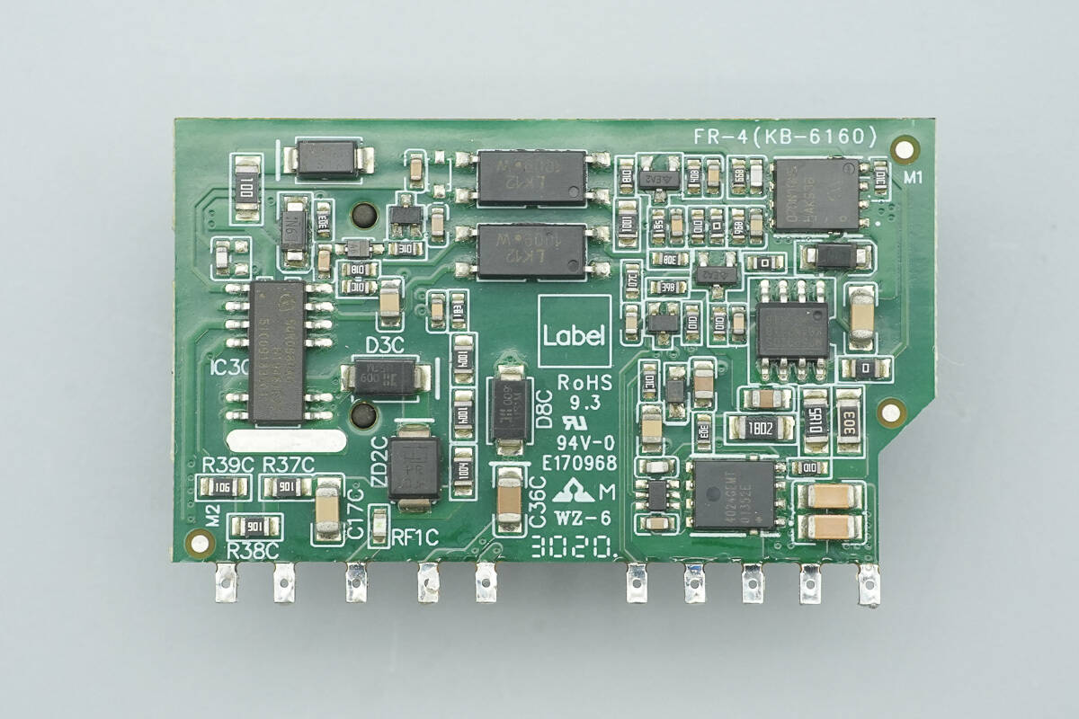
On the back side, there are standby power chips, feedback optocouplers, a synchronous rectification controller, synchronous rectifiers, and output control MOSFETs.
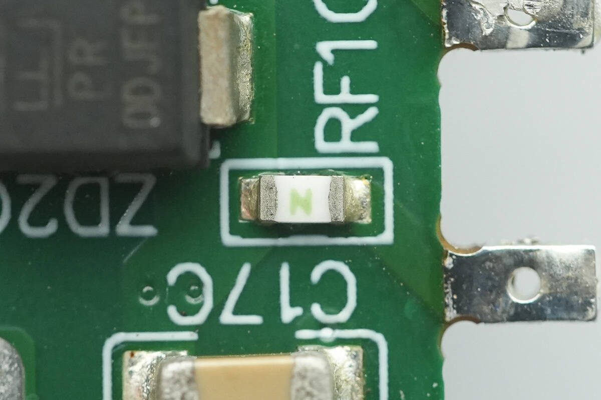
The SMD fuse is used for overcurrent protection.
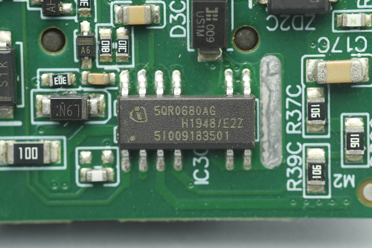
The standby power chip is from Infineon, model ICE5QR0680AG. It integrates an 800V MOSFET inside, supports 42W output power across a wide voltage range, includes comprehensive protection mechanisms, and comes in a DSO-12 package.
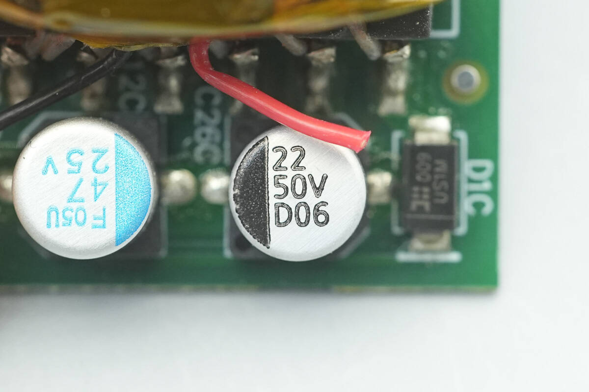
The filter capacitor supplying power to the master control chip is rated at 22 μF, 50 V.
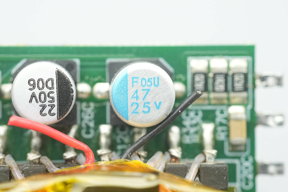
The other filter capacitor is rated at 47 μF, 25 V.
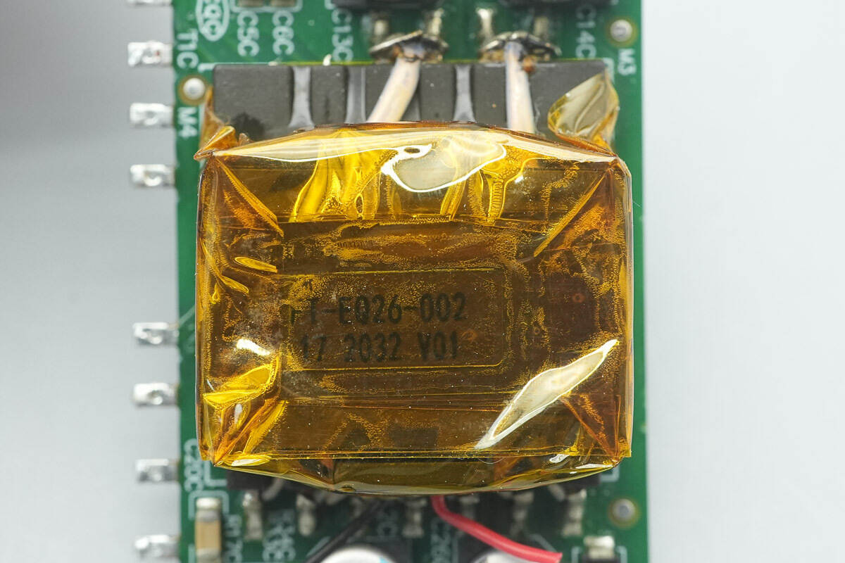
The transformer is tightly wrapped with high-temperature adhesive tape for insulation.
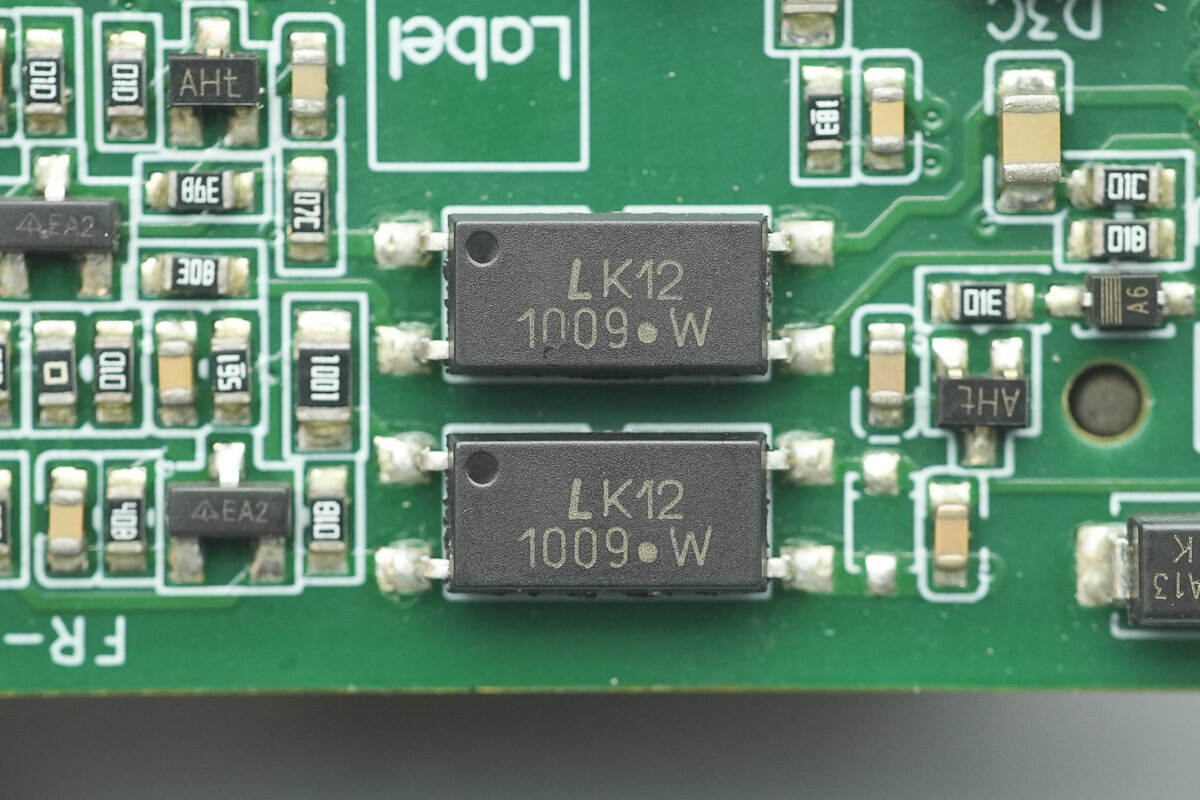
LITEON LTV1009 optocouplers are used for output voltage feedback.
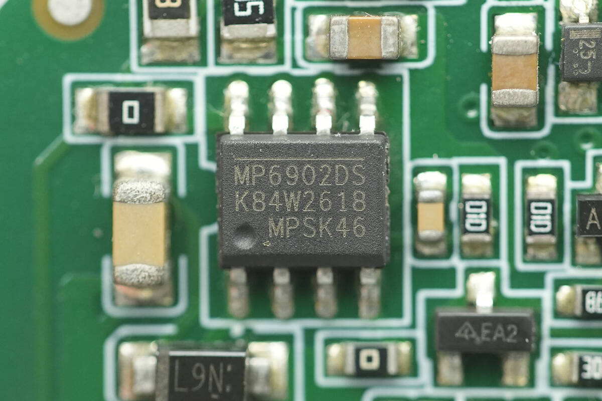
The synchronous rectifier controller is from MPS, model MP6902. It is a fast turn-off synchronous rectifier controller, supporting DCM and quasi-resonant flyback applications, with support for 12V standard and 5V logic voltage synchronous rectifiers. It operates within a voltage range of 8-24V and comes in an SOIC-8 package.
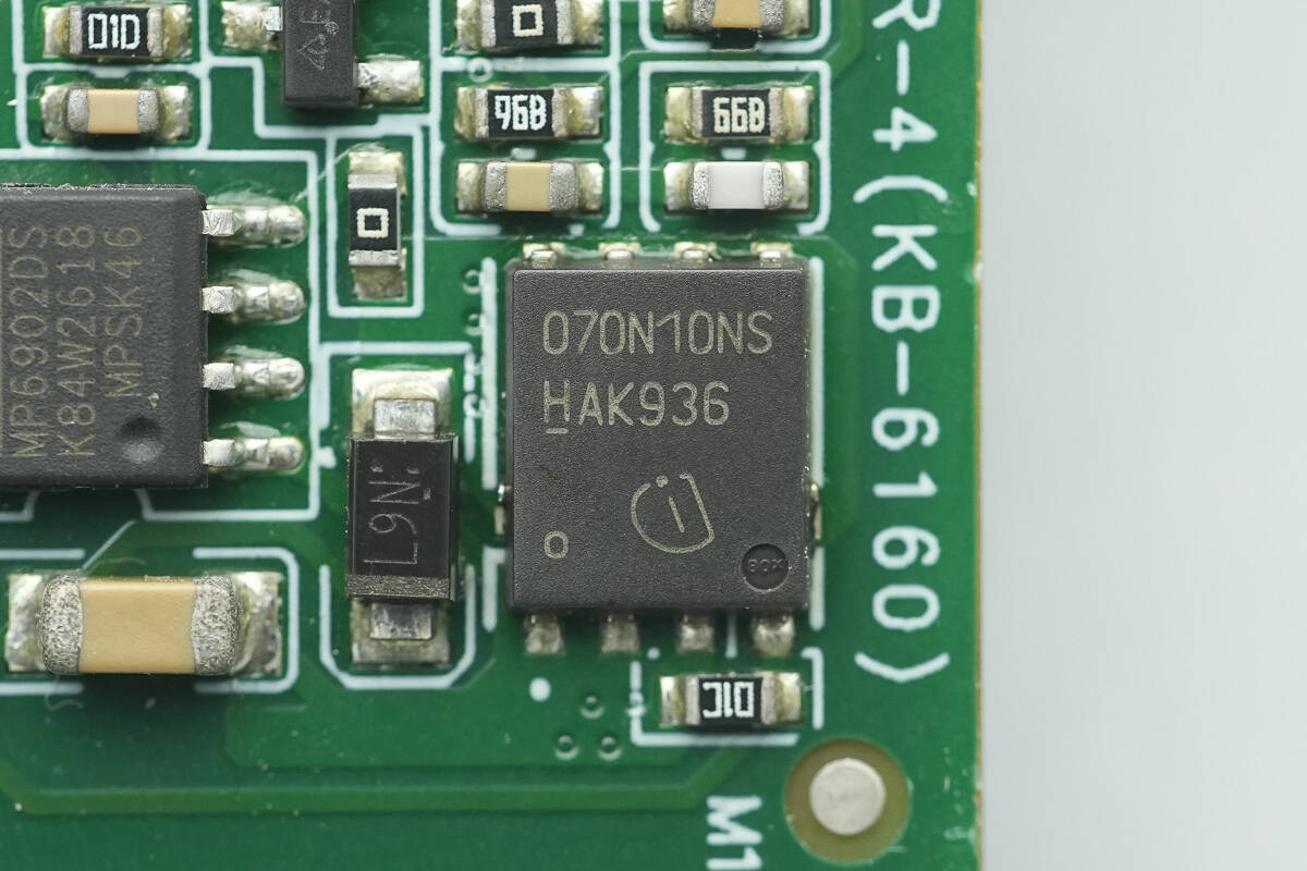
The synchronous rectifier uses Infineon BSC070N10NS3G.
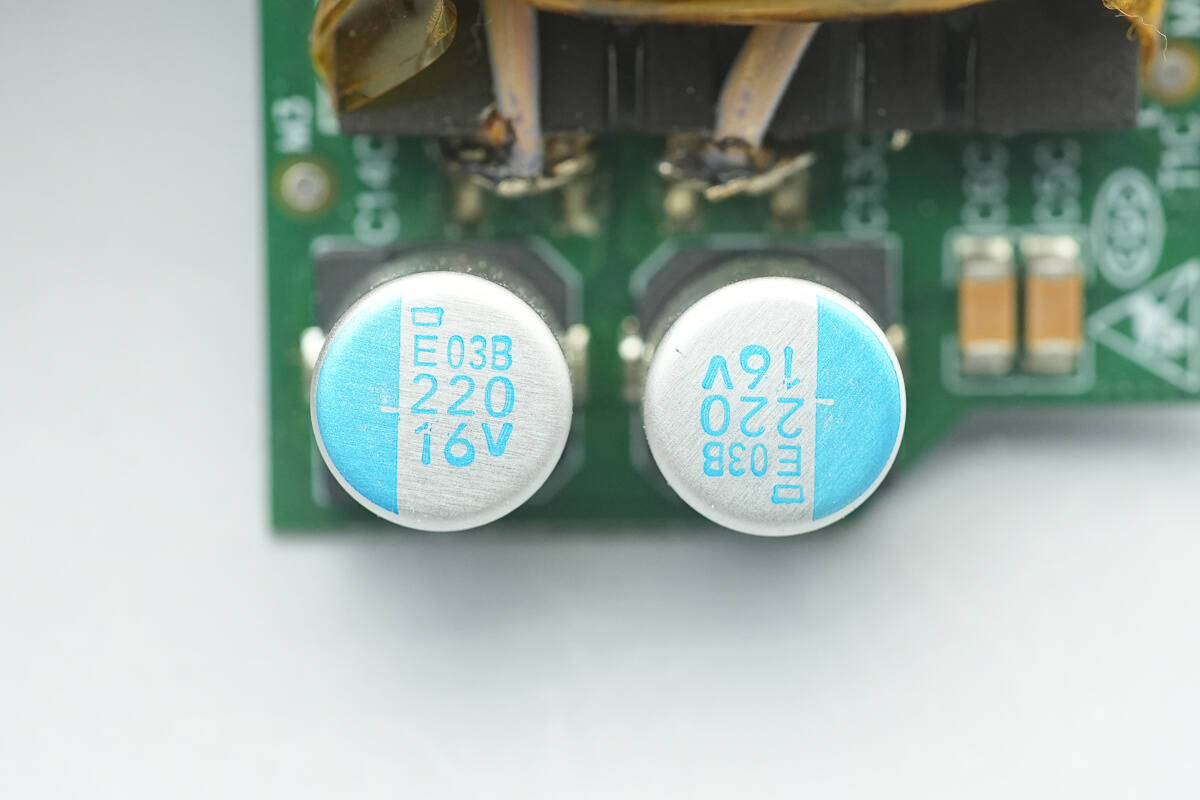
The two filter capacitors are from NCC, PXE series conductive polymer solid aluminum electrolytic capacitors, with a lifespan of 15,000 hours, and are rated at 220 μF, 16 V.
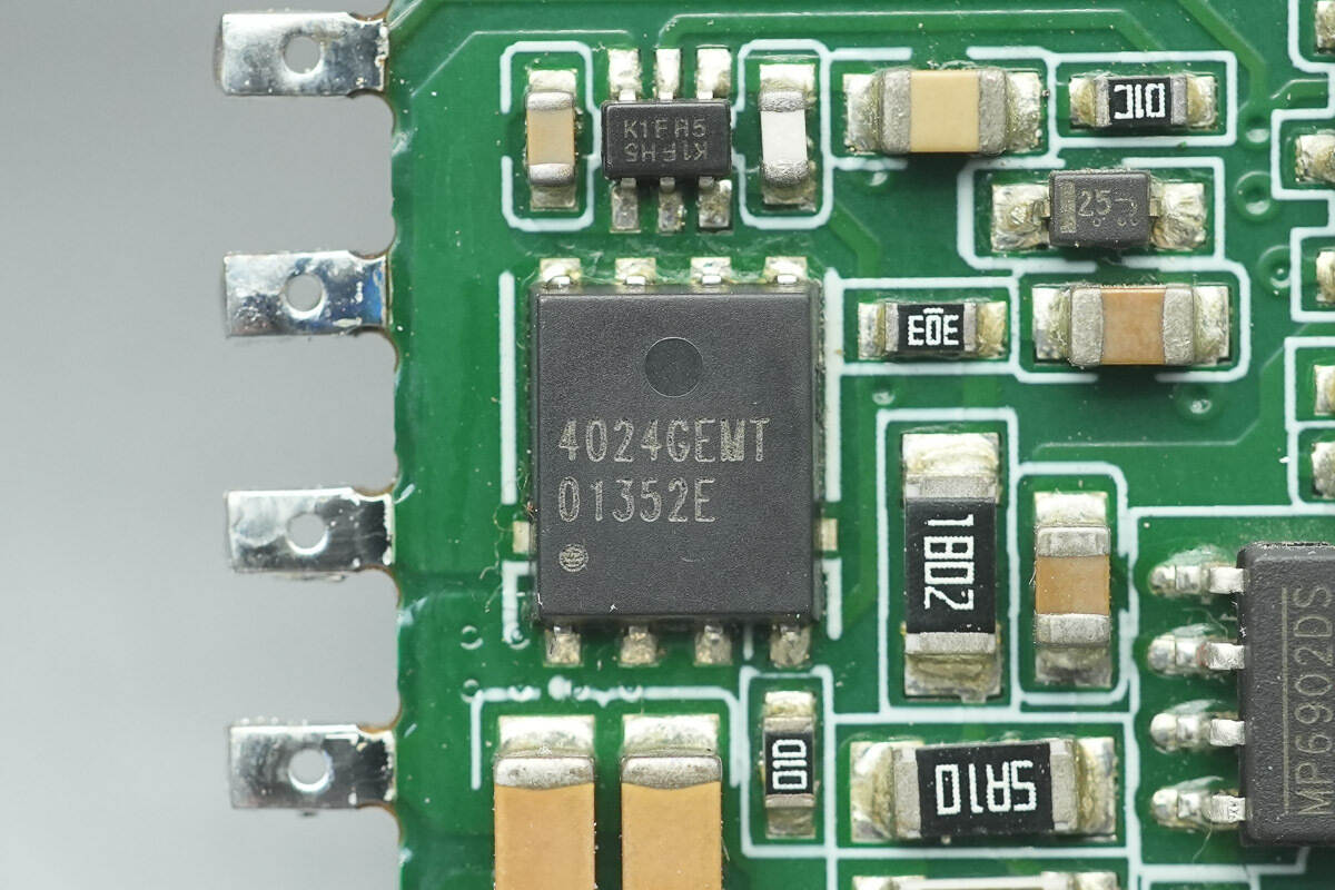
The output control MOSFET is from APEC, model AP4024GEMT. It is an NMOS, rated at 30 V, with an on-resistance of 4.5 mΩ, and comes in a PMPAK 5x6 package.
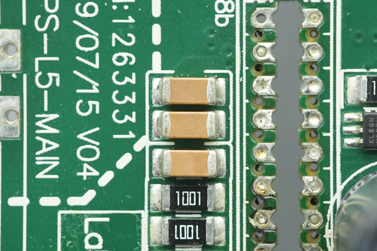
Three parallel MLCCs close-up.
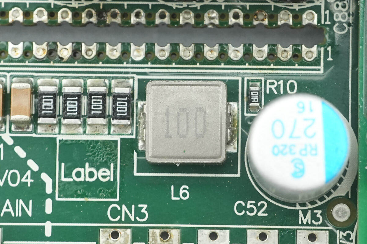
Close-up of a 10μH alloy inductor.
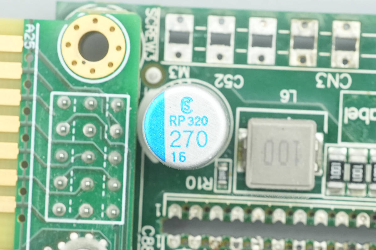
The filter capacitor is from Elite, URP series conductive polymer aluminum solid capacitor, rated at 270 μF, 16 V.
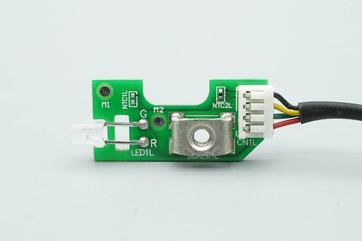
The indicator PCB has an indicator light and an NTC thermistor.
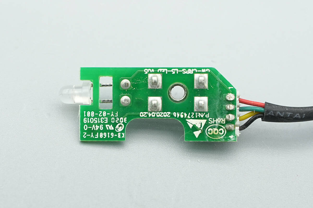
The back side has no components.
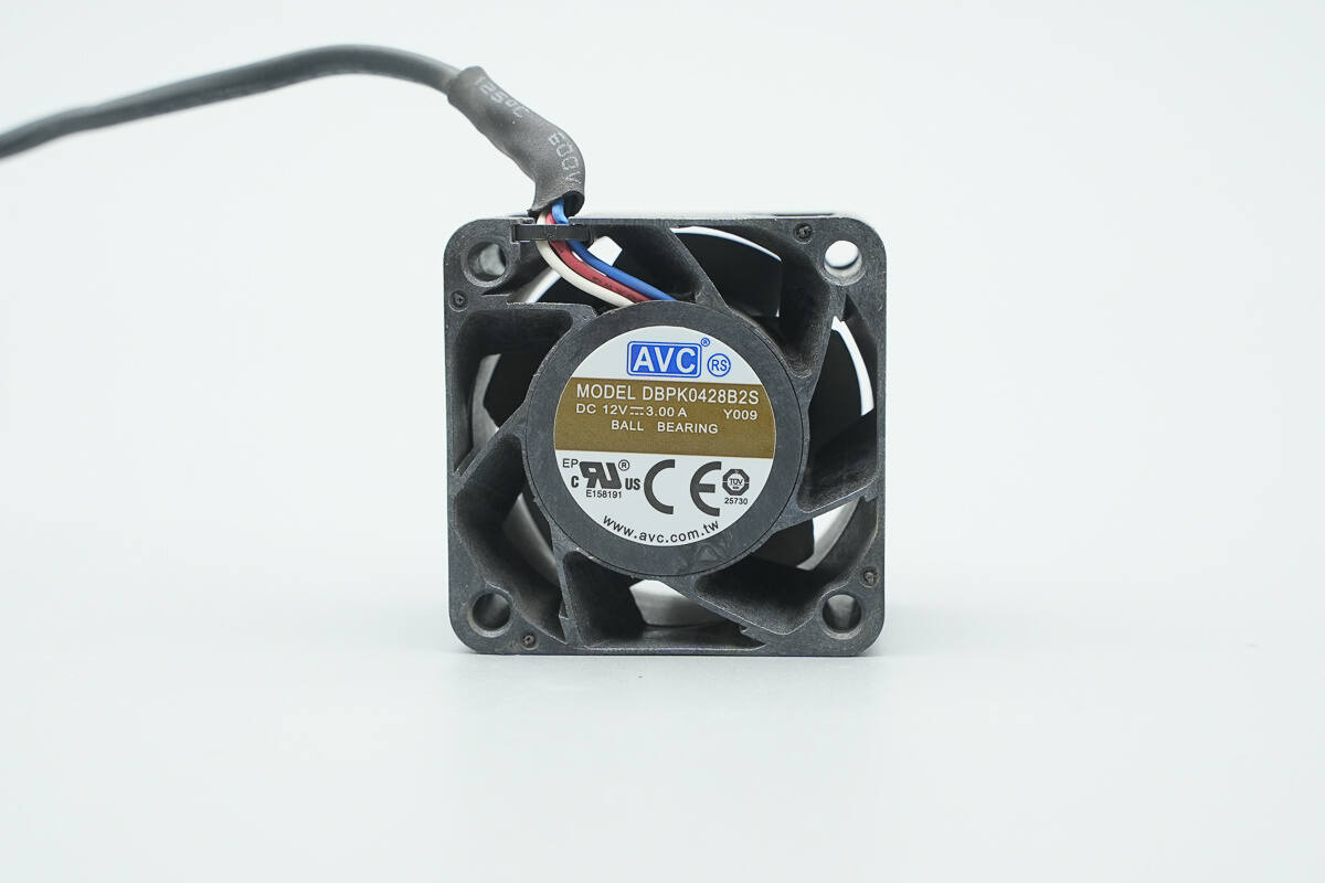
The cooling fan is from AVC, model DBPK0428B2S. It is rated at 12V, 3A, and features static blades.

Well, those are all components of the GreatWall 3000W Platinum CRPS Power Supply.
Summary of ChargerLAB
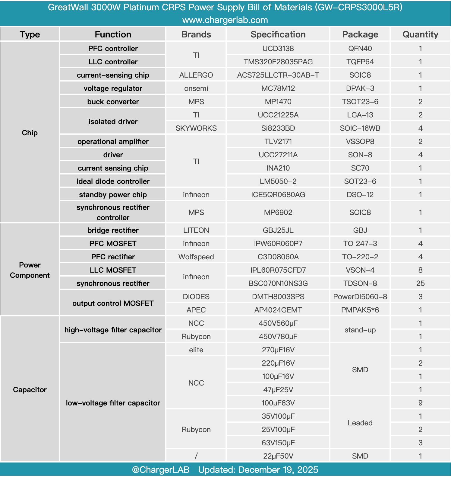
Here is the component list of the GreatWall 3000W Platinum CRPS Power Supply for your convenience.
It supports 100-240V AC input and 240V HVDC input, with a rated output power of 3000W. The main output voltage is 54V, with a rated output current of 55A. The standby power output voltage is 12V, with an output current of 2A.
After taking it apart, we found that it uses a TI control scheme. The UCD3138 is used for PFC control, paired with Infineon IPW60R060P7 MOSFETs and Wolfspeed C3D08060A SiC diodes, driven by the TI UCC21225A. The TMS320F28035PAG is used for LLC control, with MOSFETs driven by the SKYWORKS SI8233BD. The TI UCC27211A drives the synchronous rectifiers.
The LLC MOSFETs and synchronous rectifiers are from Infineon, using the IPL60R075CFD7 paired with the BSC070N10NS3G. The standby power uses the Infineon ICE5QR0680AG, while the synchronous rectifier controller is the MPS MP6902. The capacitors are from NCC and Rubycon. The power supply is constructed using multiple PCBs soldered together, which helps with airflow, enhances heat dissipation, and makes efficient use of space, with solid and reliable workmanship and materials.
Related Articles:
1. Teardown of Belkin BoostCharge Pro Dual USB-C 67W GaN Wall Charger (WCH020yz)
2. Teardown of Huntkey 140W GaN Charger (HKC14028050-0B1)
3. Teardown of NIU 280W E-bike Charger (DZL482015N)