Introduction
We got the Dyson HD17 Hair Dryer, which features a brand-new “r”-shaped body with a modular design. The body is 30% smaller and 20% lighter, combined with an ergonomic design for flexible and convenient handling. The hair dryer uses streamlined airflow heating technology to evenly heat the airflow and deliver it in a streamlined output.
It comes with five magnetic intelligent styling nozzles to meet daily drying and styling needs. The hair dryer has a power output of 1700W, with three-speed settings and four temperature settings, plus a one-touch cold shot button for easy styling. Next, we’ll take it apart to check out its internal components and design.
Product Appearance
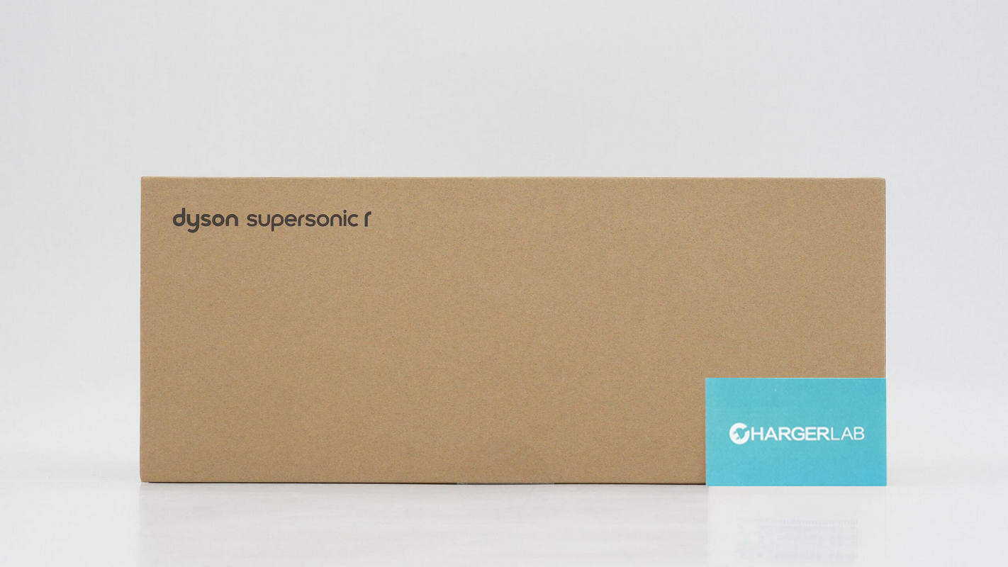
The packaging is made of cardboard, with "Dyson Supersonic r" printed in the top left corner.
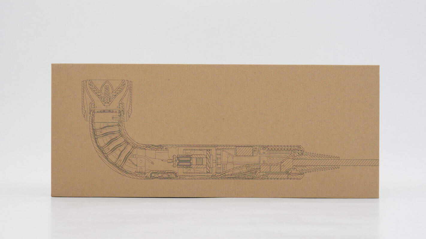
The other side features a transparent view of the hair dryer’s internal components.
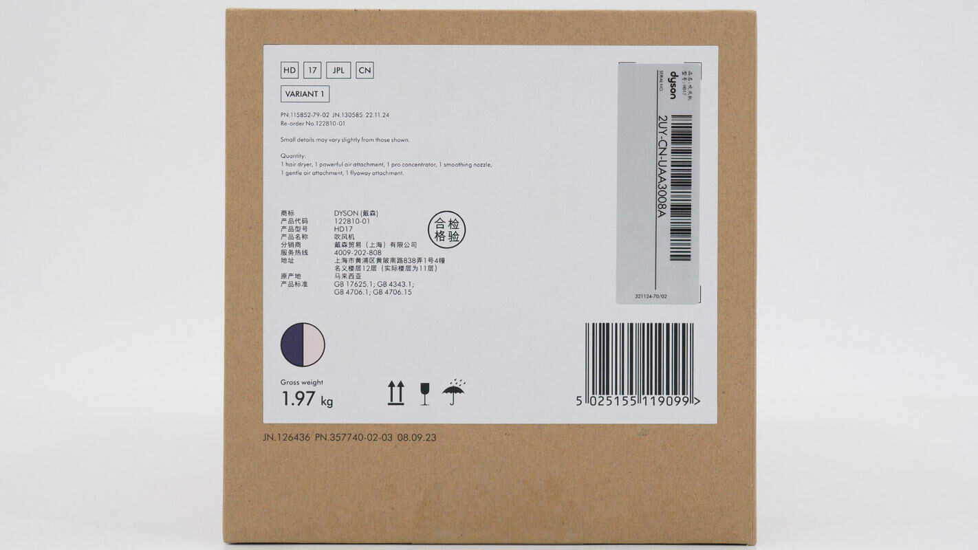
The label on the side displays the product information.
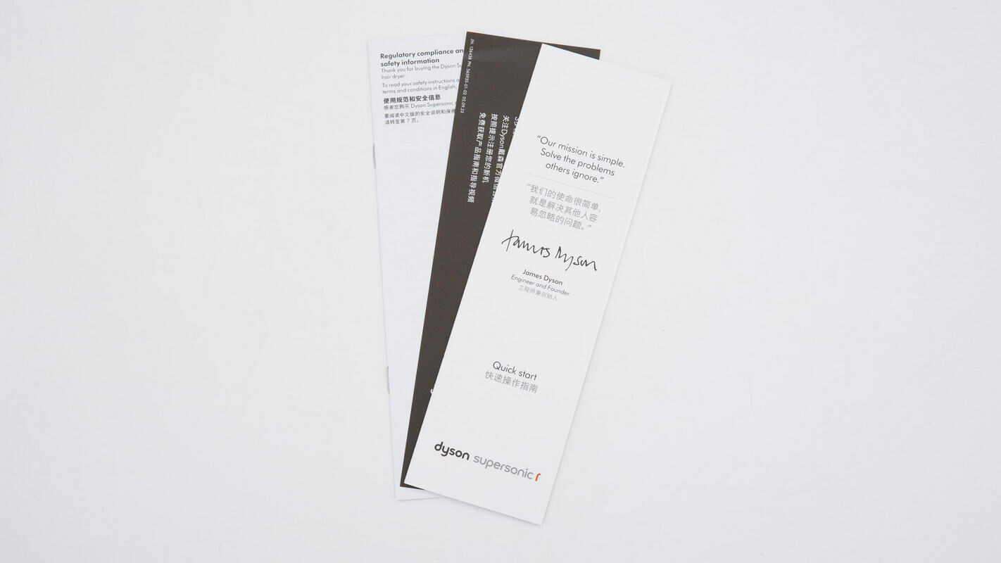
A quick start guide is included inside the packaging box.
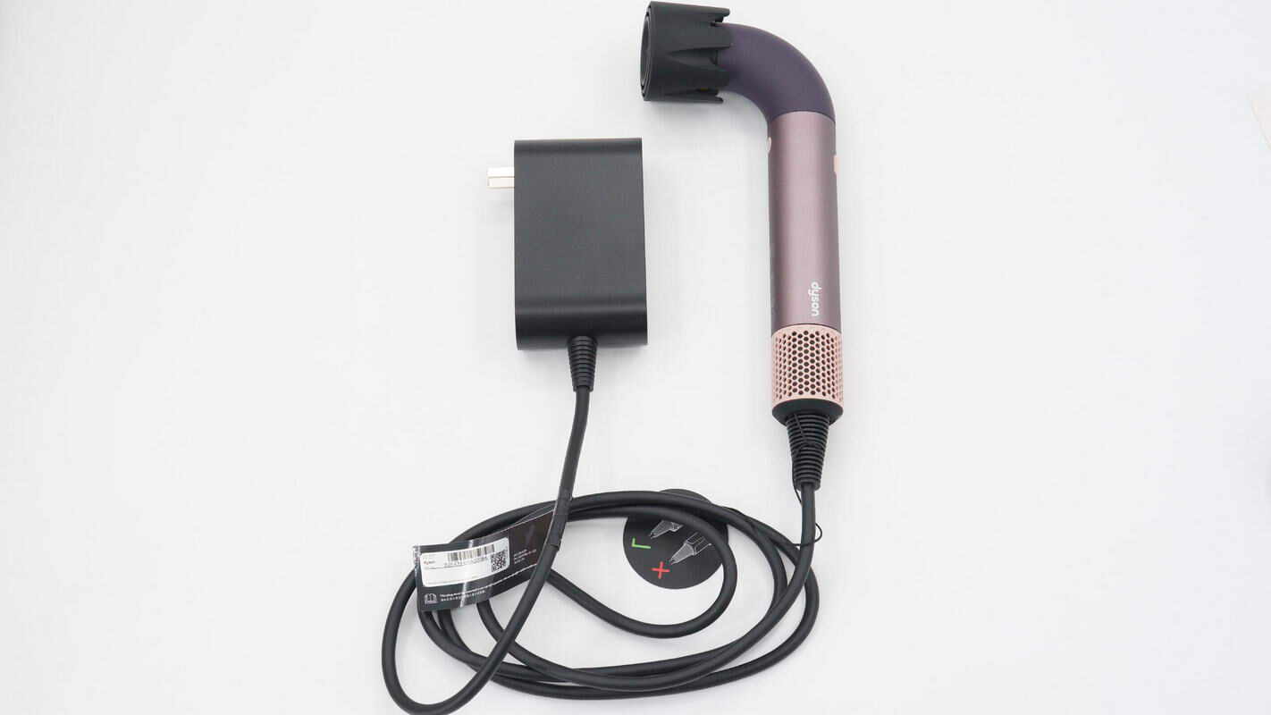
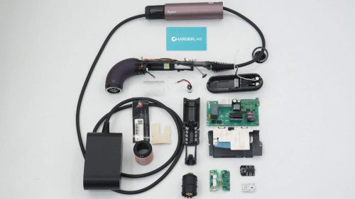
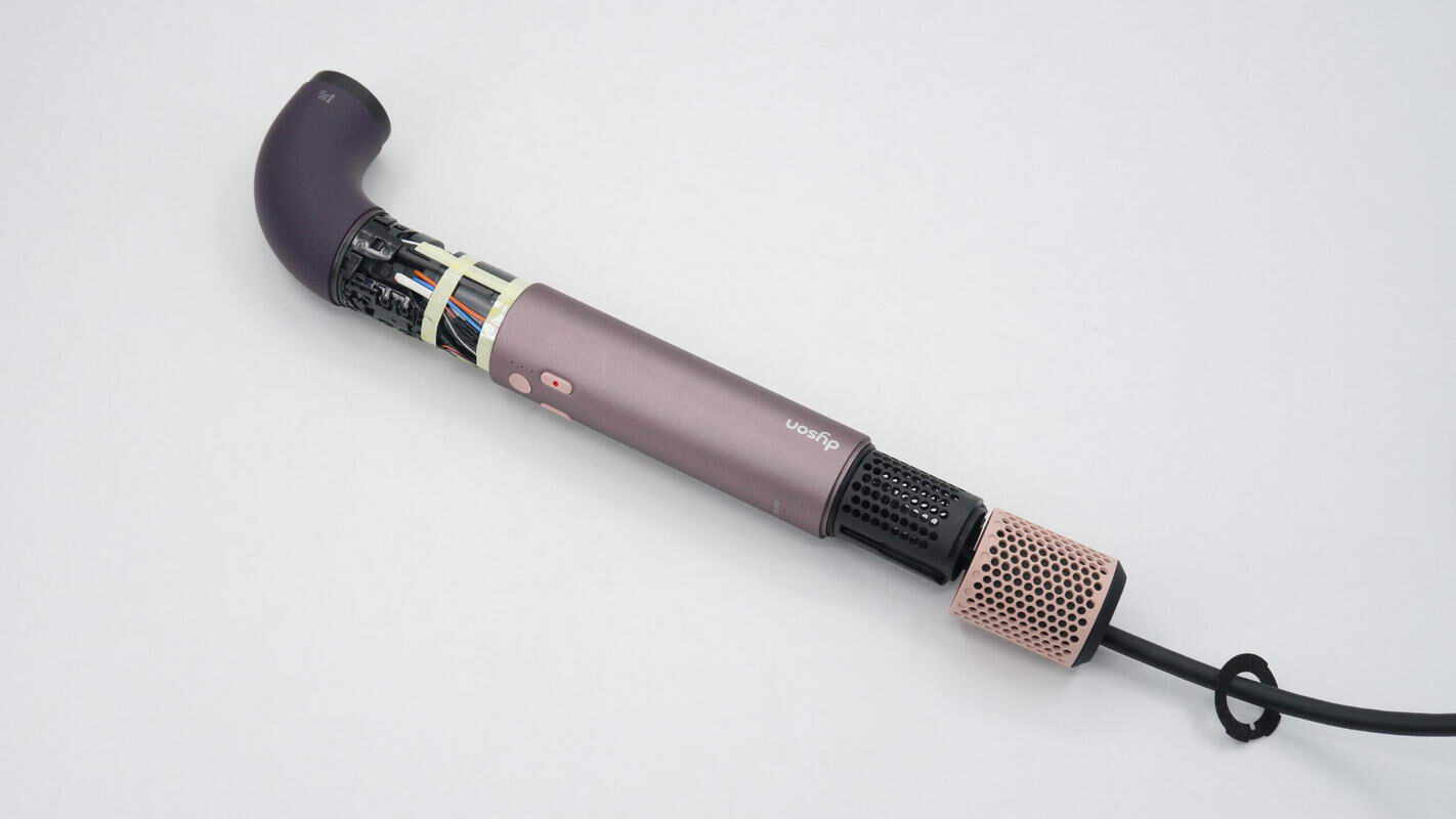
Overview of the hair dryer: its motor drive circuitry is moved from inside the dryer body to the plug, reducing the size and weight of the unit and greatly enhancing the user experience.
The label on the power cord indicates that the hair dryer must have a nozzle installed to operate.
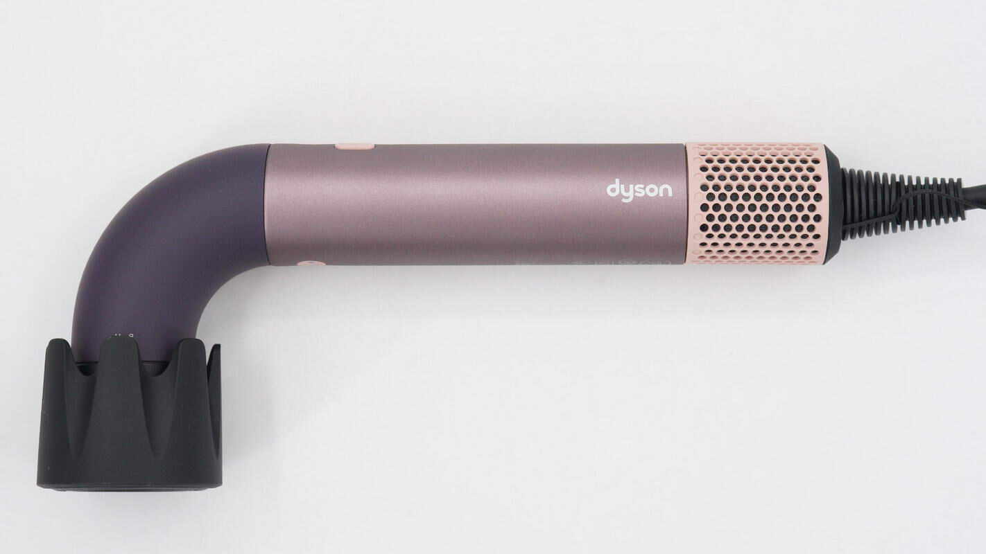
It features a purple color.
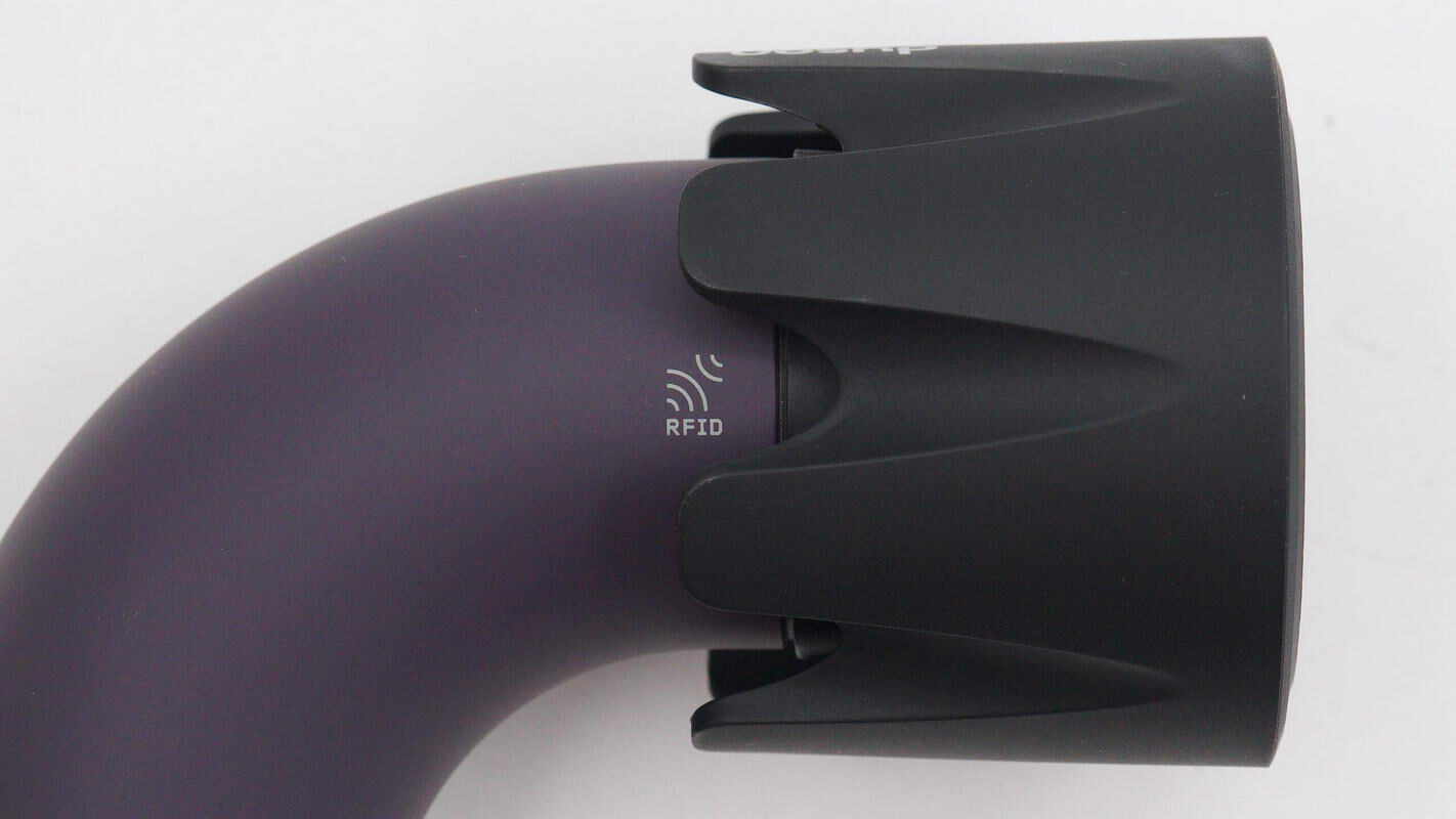
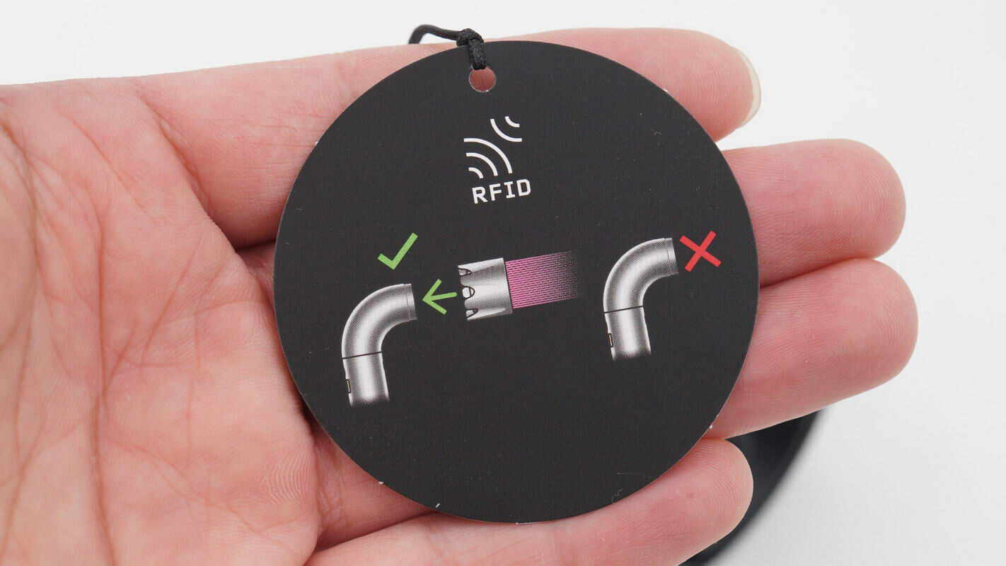
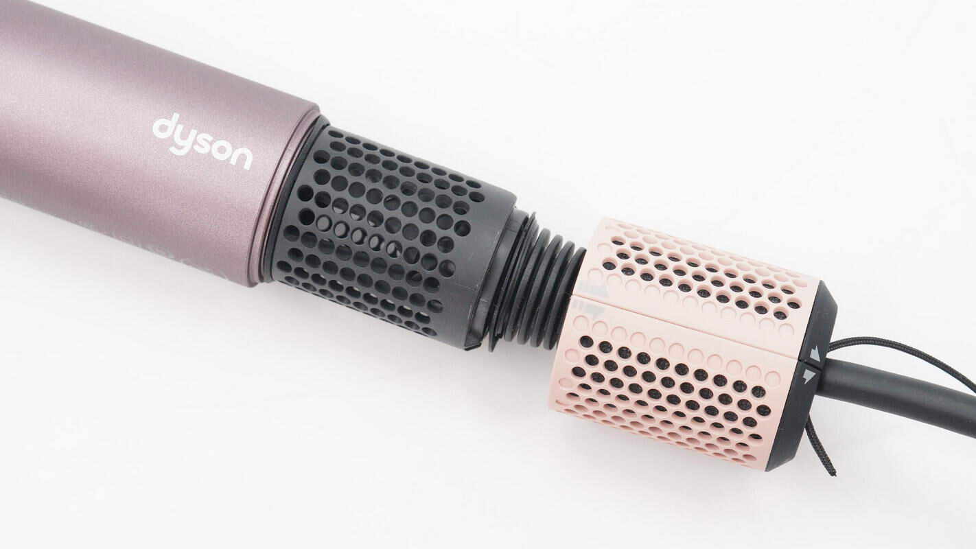
The nozzles are identified and detected using RFID technology.
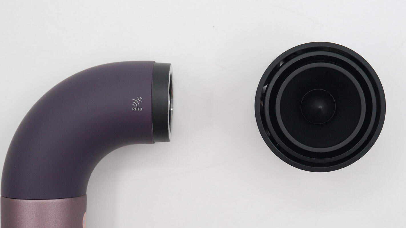
They use magnetic attachment for easy and quick replacement.
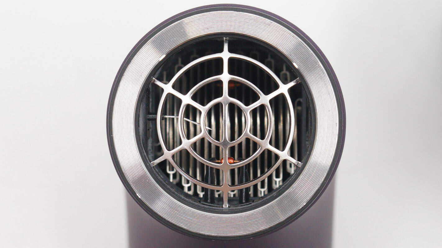
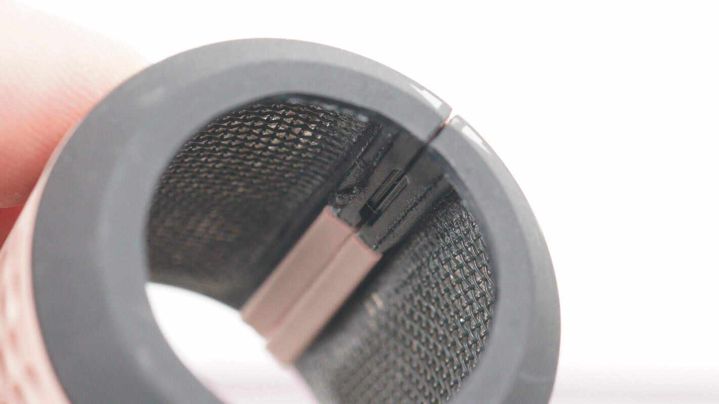
The air outlet is equipped with a protective mesh, through which the internal heating elements can be seen.
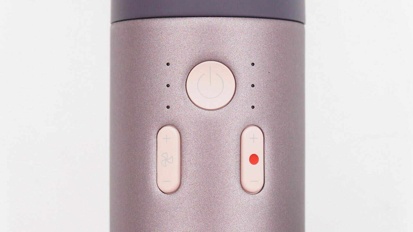
The handle features a power button, with the left side housing the fan speed control button and its indicator light, and the right side containing the temperature control button and its indicator light.
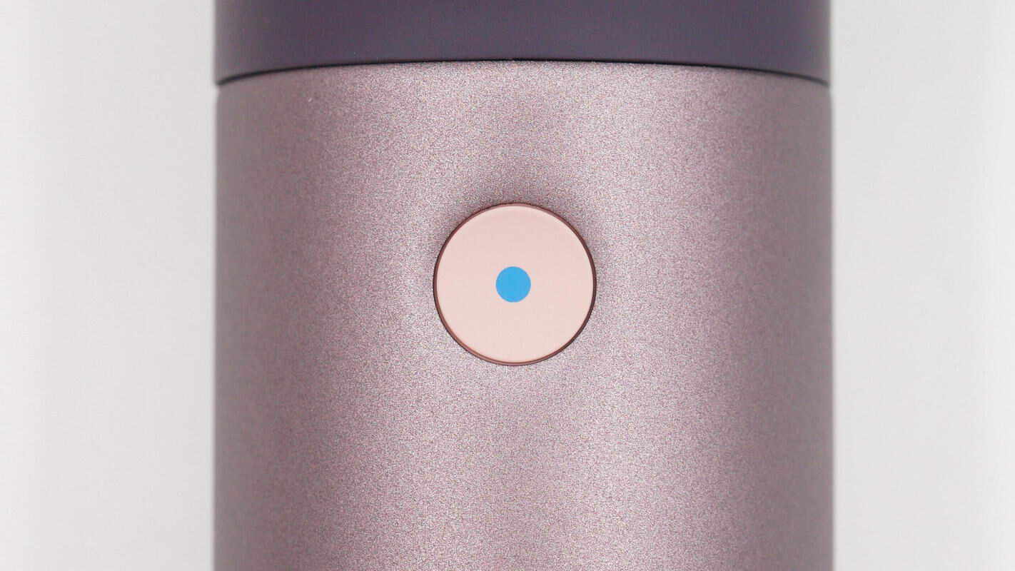
On the opposite side, there is a cold shot button.
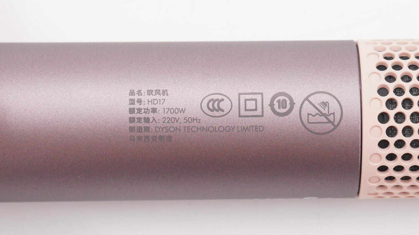
The label shows the specifications: model HD17, rated power 1700W, rated input 220V\~50Hz, and it has passed CCC certification.
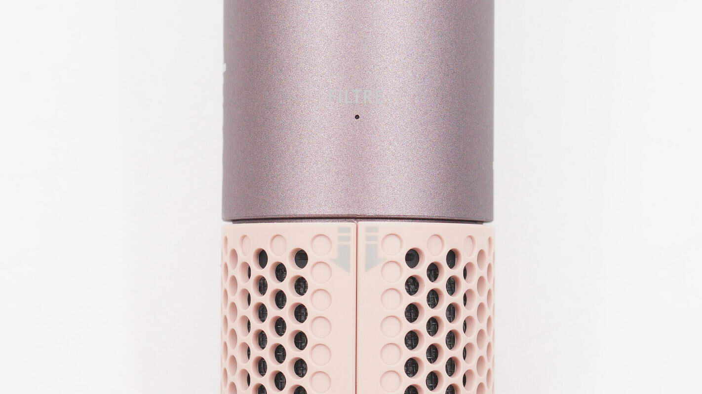
The indicator light is used to signal the installation status of the filter.
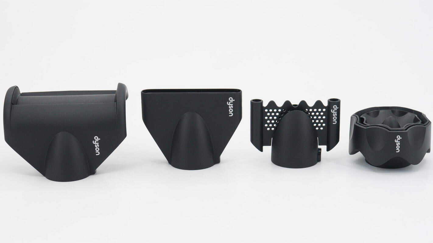
A total of five nozzles are included.
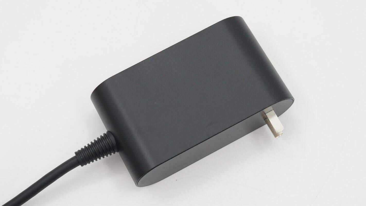
The plug houses the motor drive circuitry inside.
The top is printed with "Dyson."
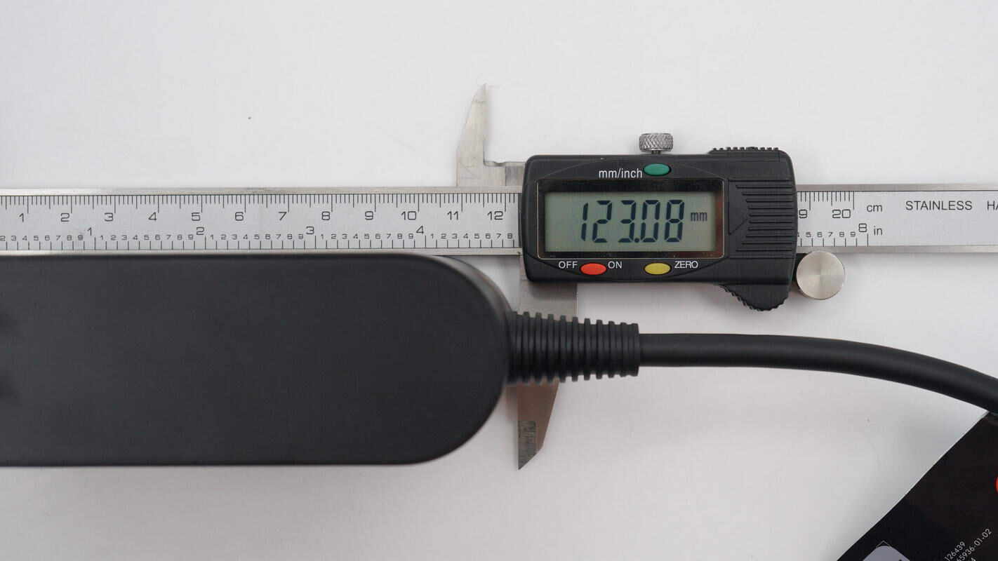
The length of the plug is about 123 mm (4.84 inches).
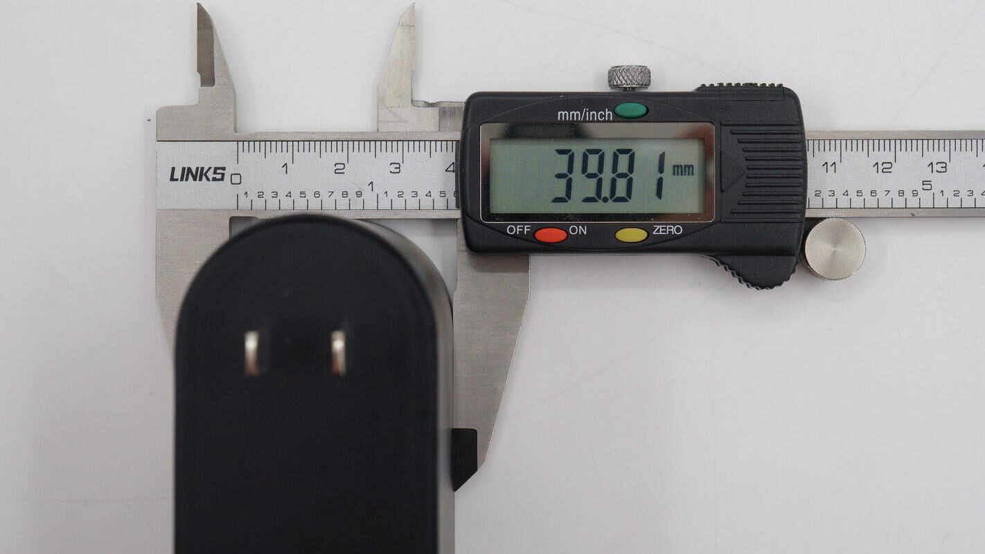
The width is about 40 mm (1.57 inches).
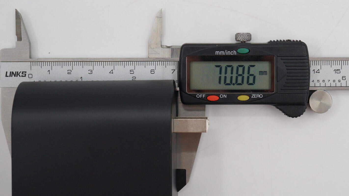
The height is about 71 mm (2.8 inches).
Teardown
Next, let's take it apart to see its internal components and structure.
First, remove the intake filter. The handle casing is secured with screws.
Unscrew the mounting screws and remove the handle casing.
The handle is secured with screws. The cold shot button is located at the top.
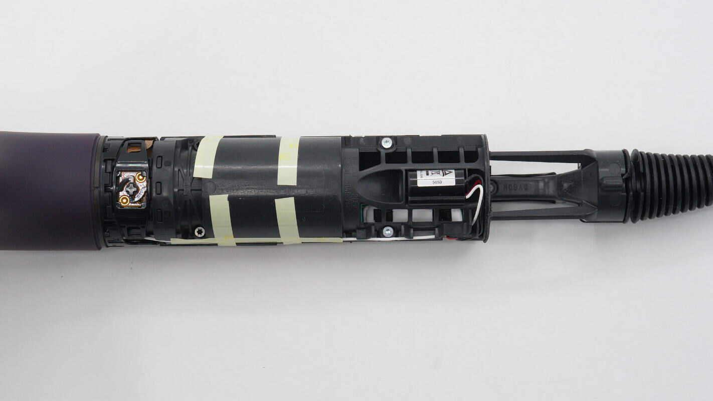
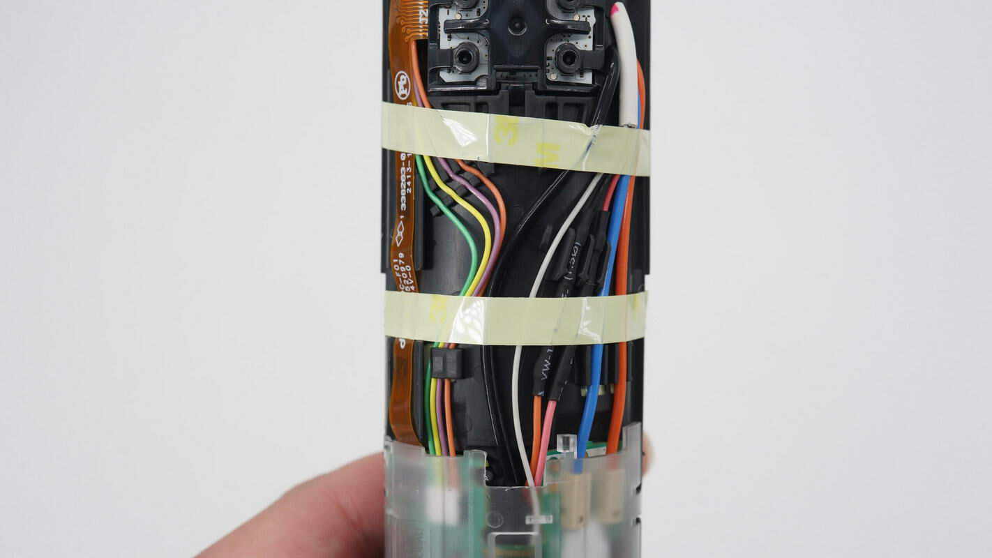
The cables are secured with tape. The PCBA module is protected by a transparent plastic casing.
The wires on the side are also secured with tape.
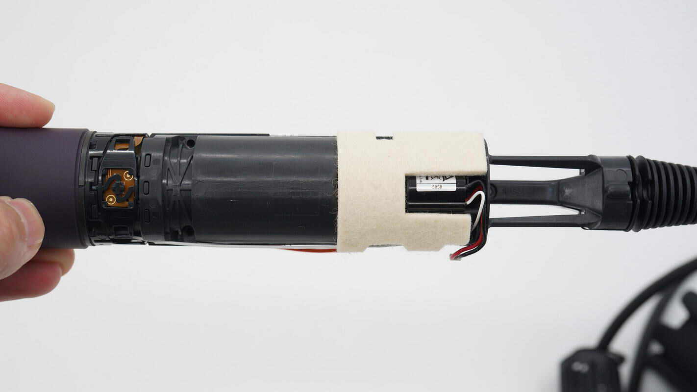
The tail end of the handle is also equipped with sound-absorbing cotton.
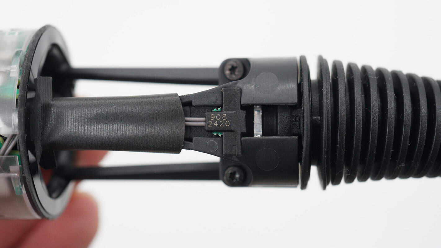
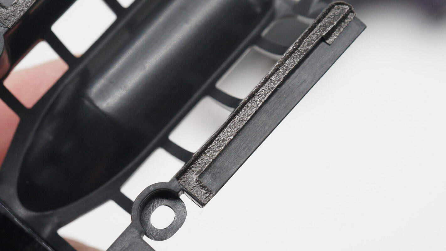
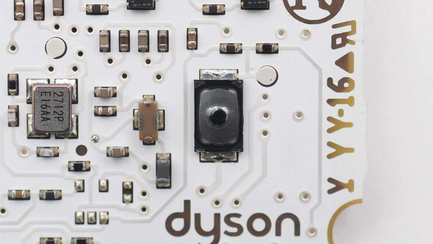
Close-up of the sensor at the tail end of the handle that detects the filter position.
There is a magnet inside the corresponding position of the filter.
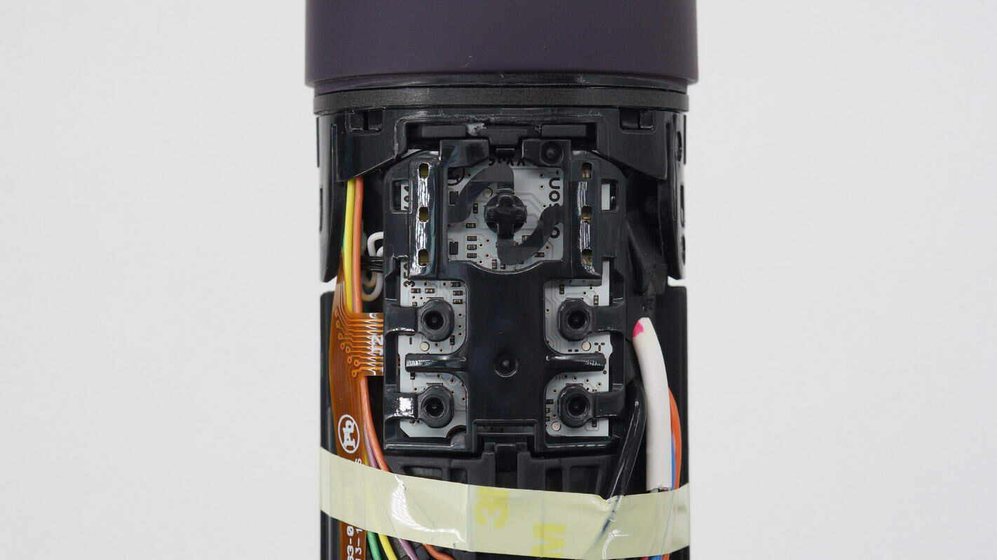
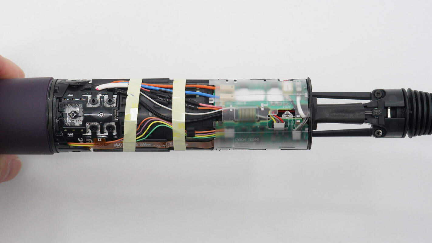
Close-up of the power switch, indicator lights, and the fan speed and temperature control buttons.
The wires are secured with clips and tape.
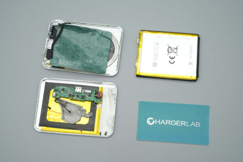
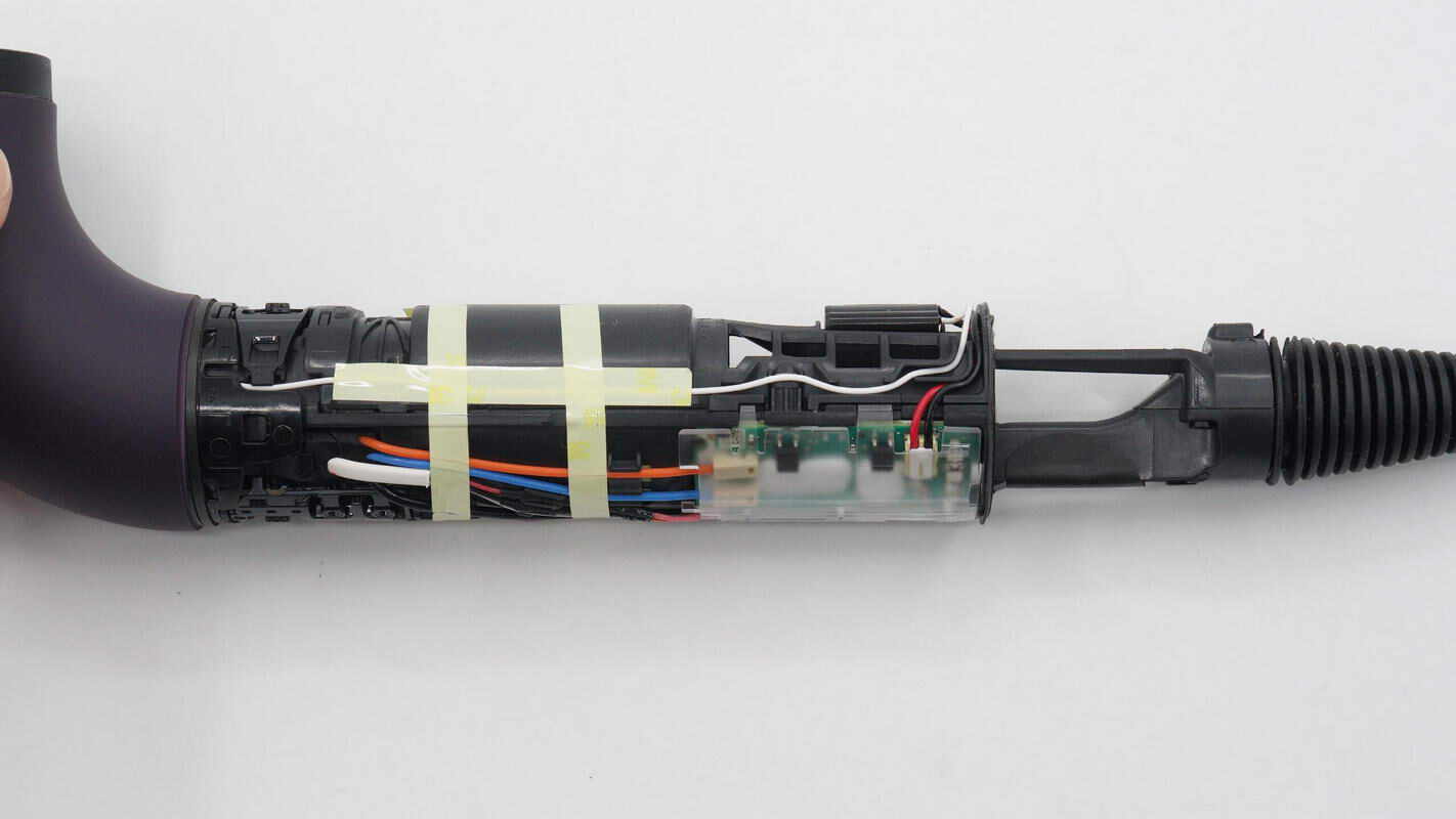
Remove the transparent plastic casing.
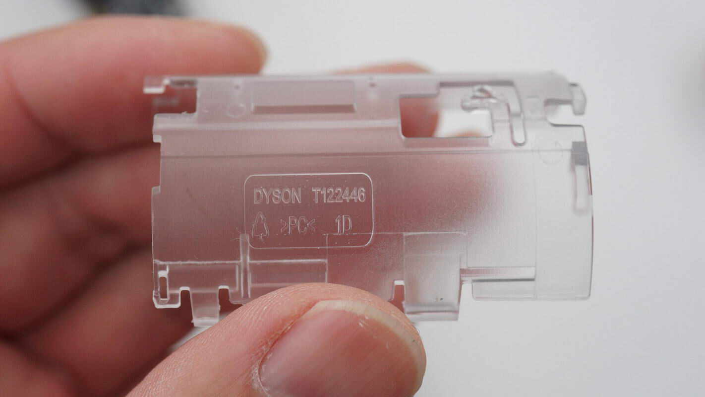
The plastic casing is made of PC material.
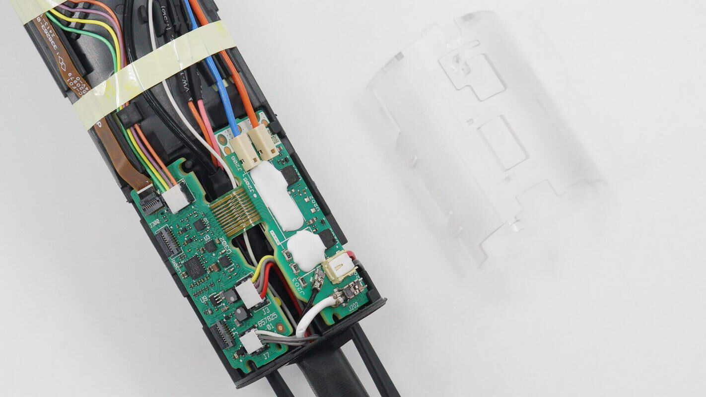
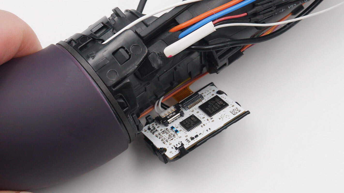
The wires are connected to the PCBA module via connectors. The PCBA module is a rigid-flex board.
The other PCB features wire connectors and ribbon cable sockets.
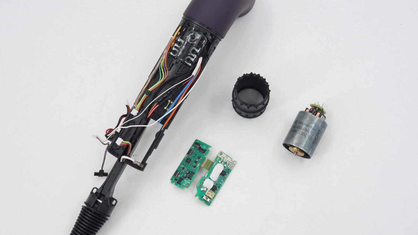
Remove the PCBA module and the brushless motor from the housing.
There is foam sealing along the edge of the housing.
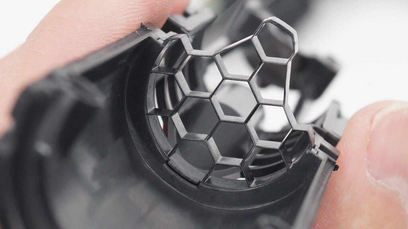
The intake has a honeycomb-patterned grille inside.
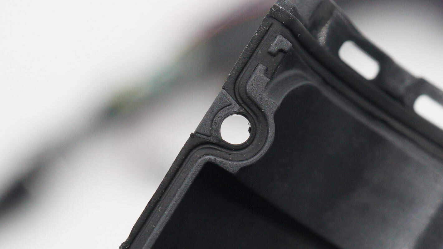
There is a rubber seal along the edge of the housing.
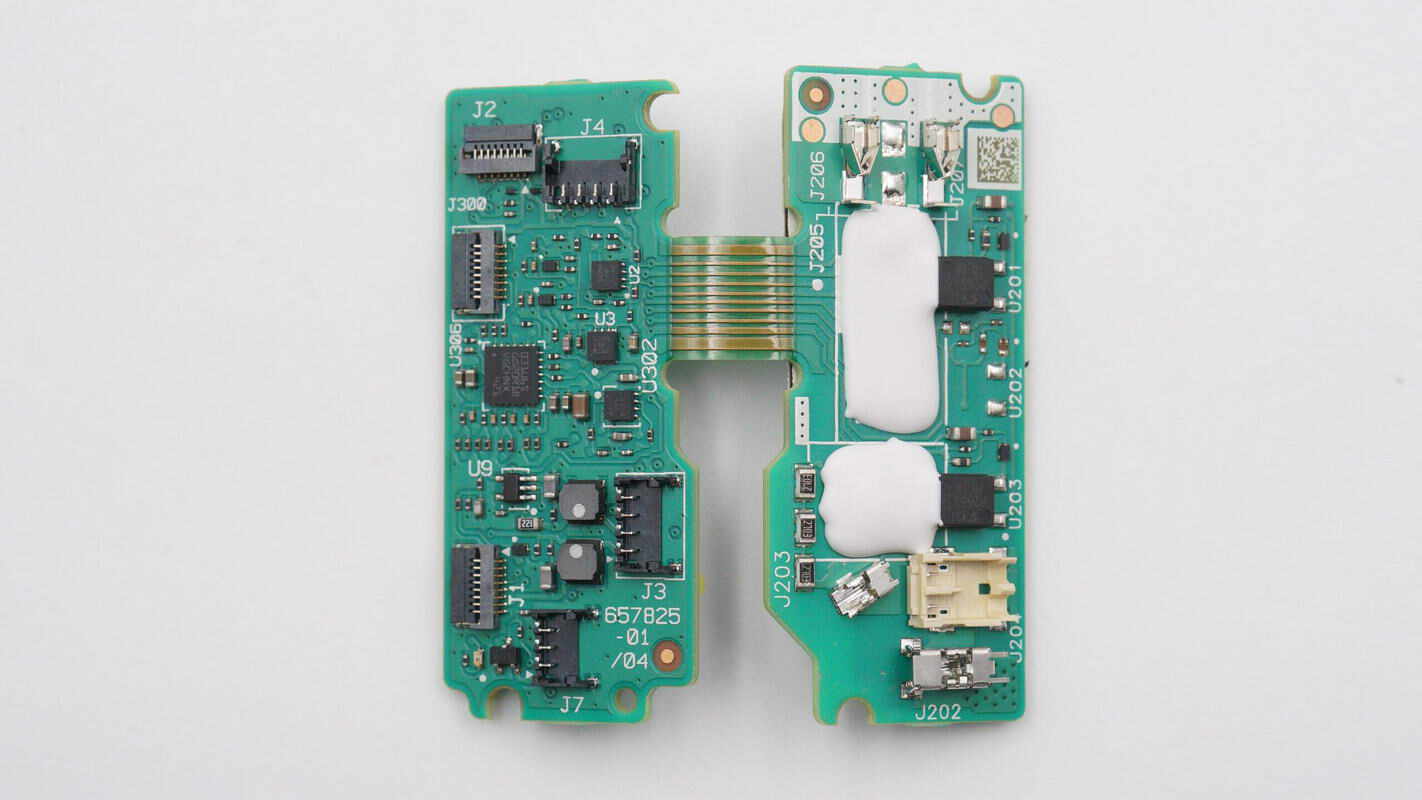
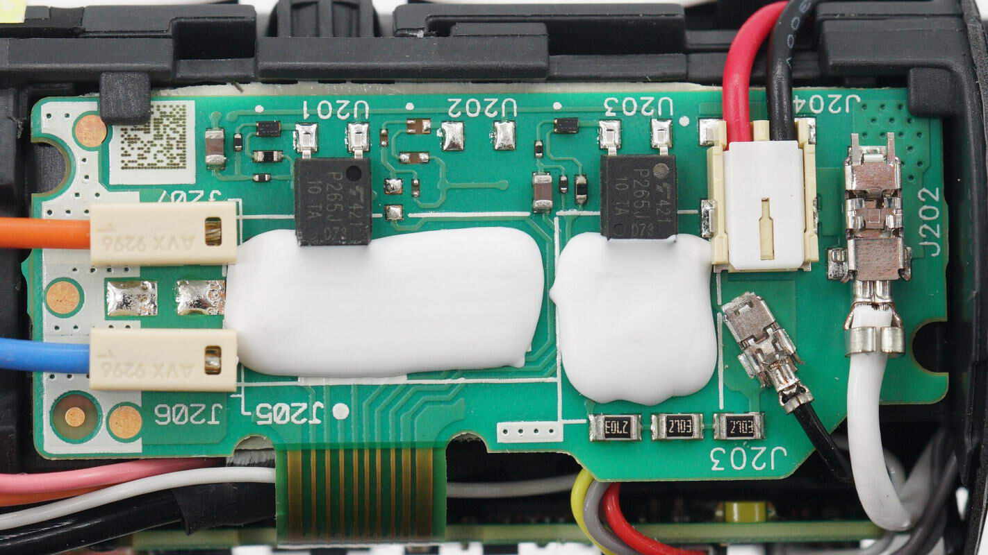
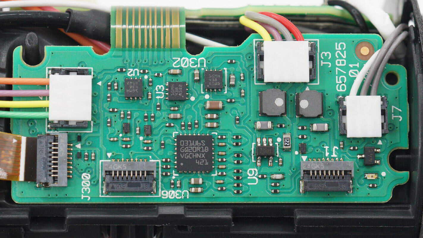
On the left side of the PCBA module, there is an MCU and three operational amplifiers, while the right side features two isolation optocouplers.
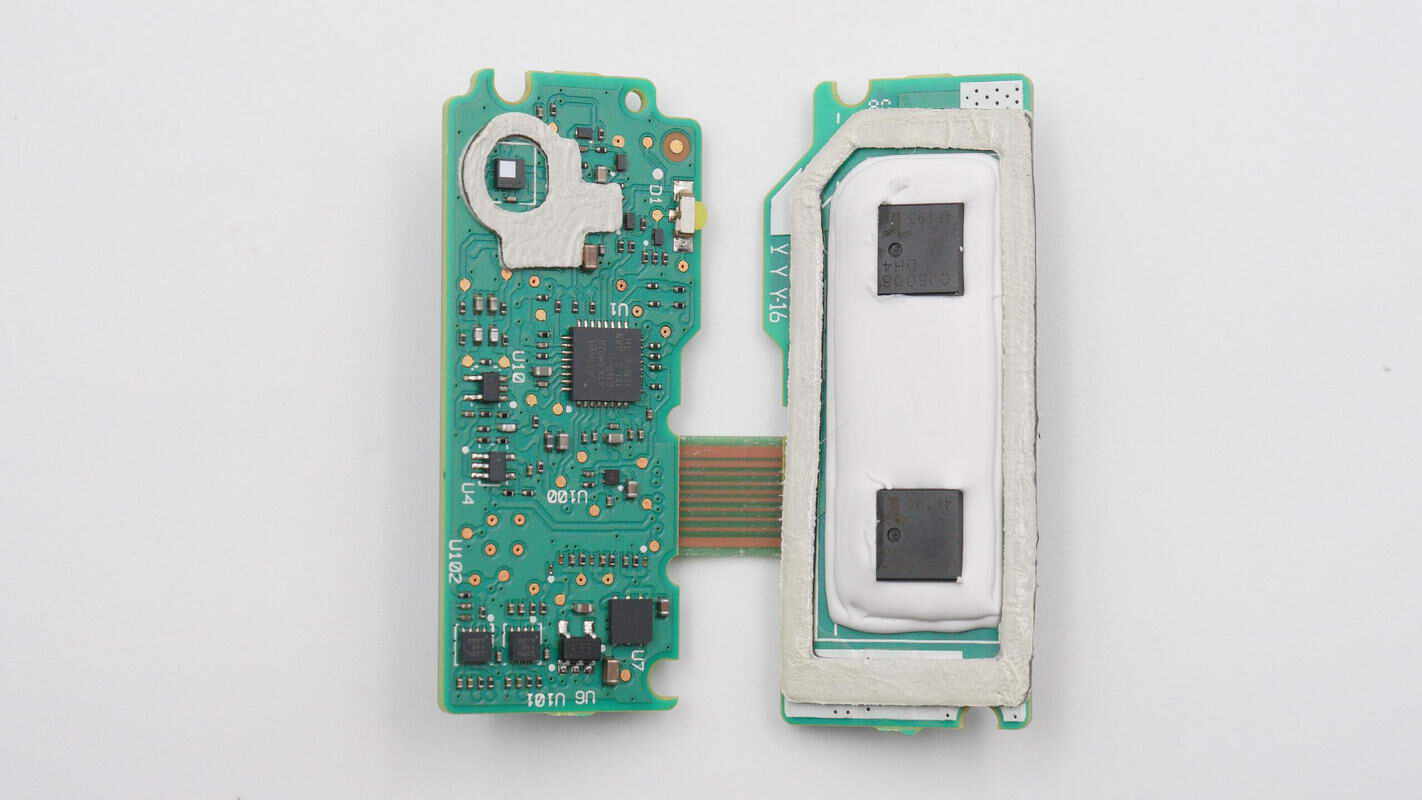
On the back, there is a pressure sensor and an MCU; on the other side, two thyristors are installed. The pressure sensor is used to monitor the filter status, and the thyristors are sealed with adhesive.
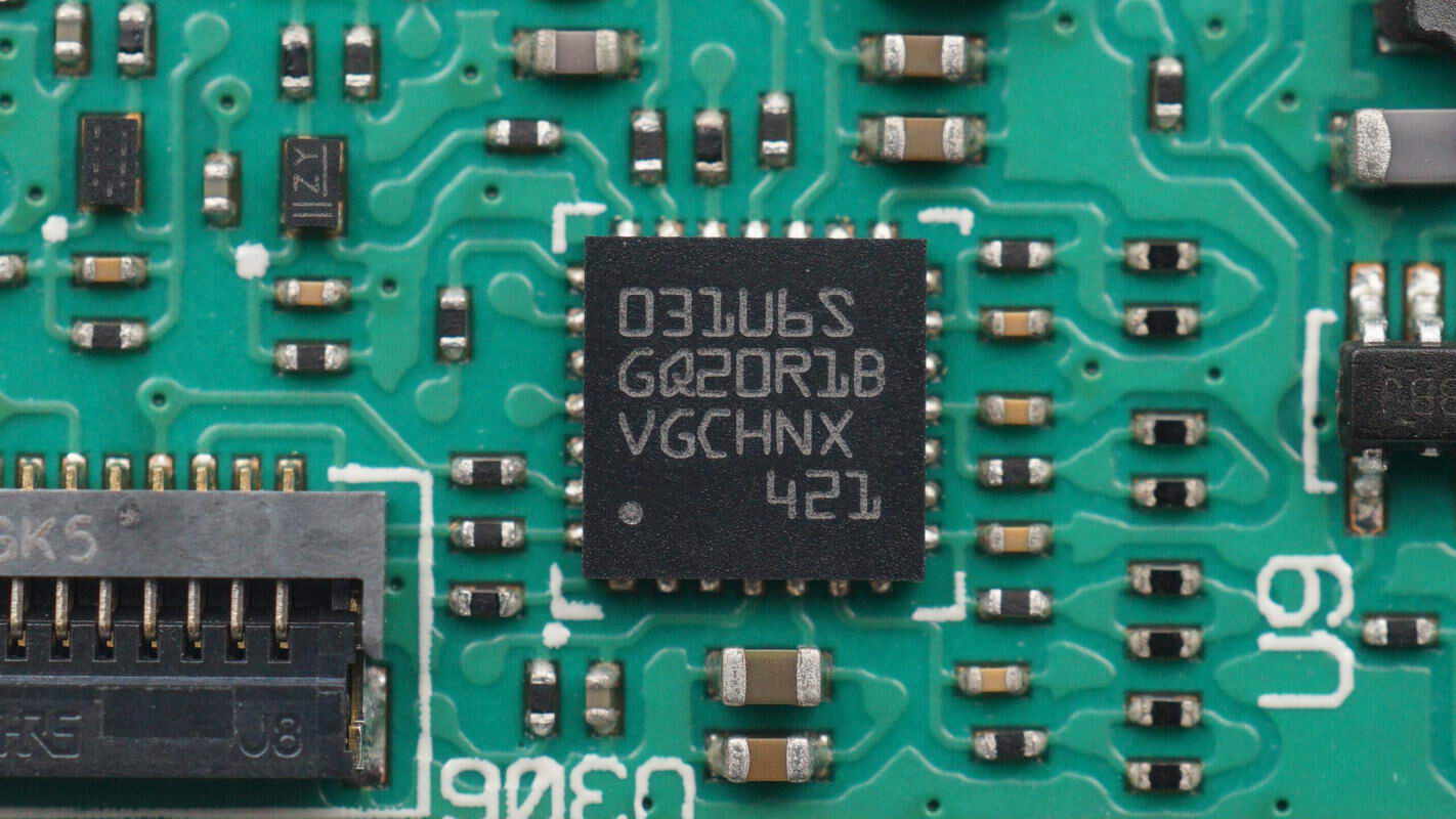
The MCU is from STMicroelectronics, model STM32L031G6U6S. It features an ARM Cortex-M0+ core running at 48MHz, with 64KB Flash and 8KB SRAM, housed in a UFQFPN28 package.
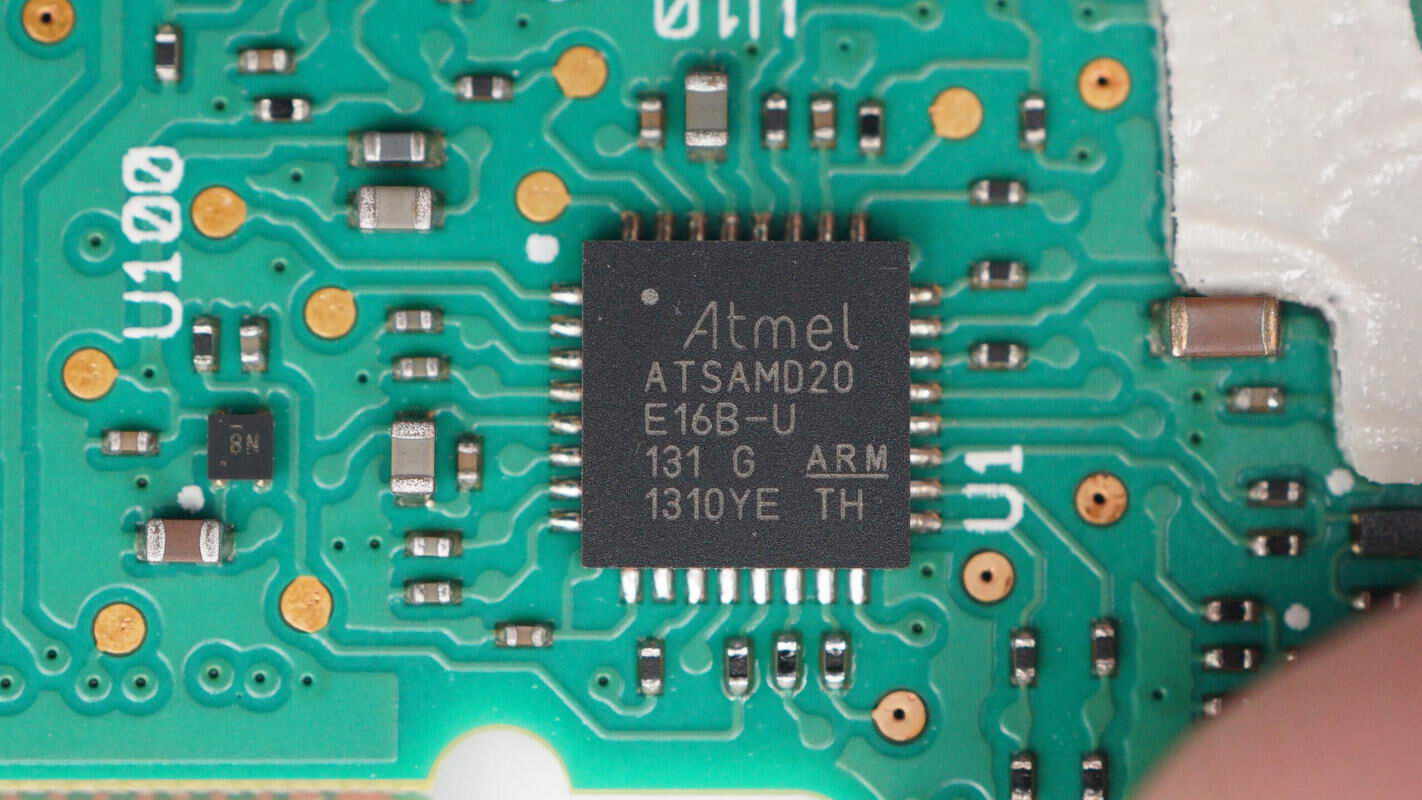
The other MCU is from Microchip, model ATSAMD20E16B-U. It features a 32-bit Cortex-M0+ core, with 64KB Flash and 8KB SRAM, used for overall control of the hair dryer, and comes in a 32-pin VQFN package.
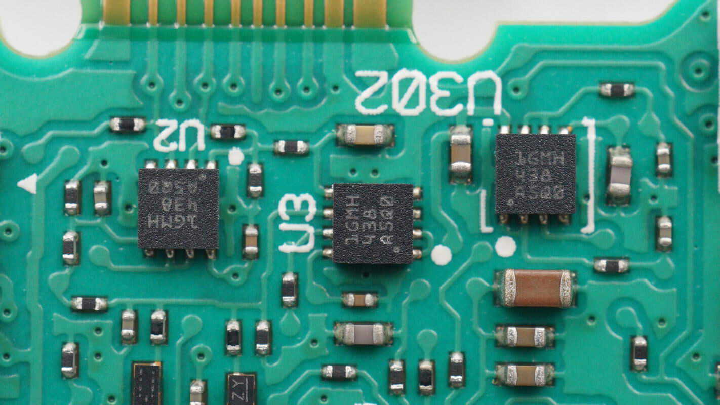
The three Op-Amps are from TI, marked with 1GMH, model TLV9002. They are low-power dual op-amps with rail-to-rail input and output, housed in WSON8 packages.
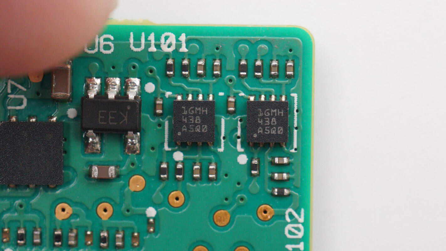
Close-up of the other two TLV9002 Op-Amps.
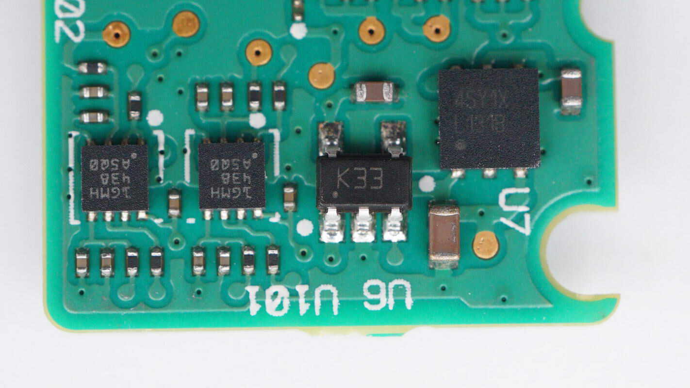
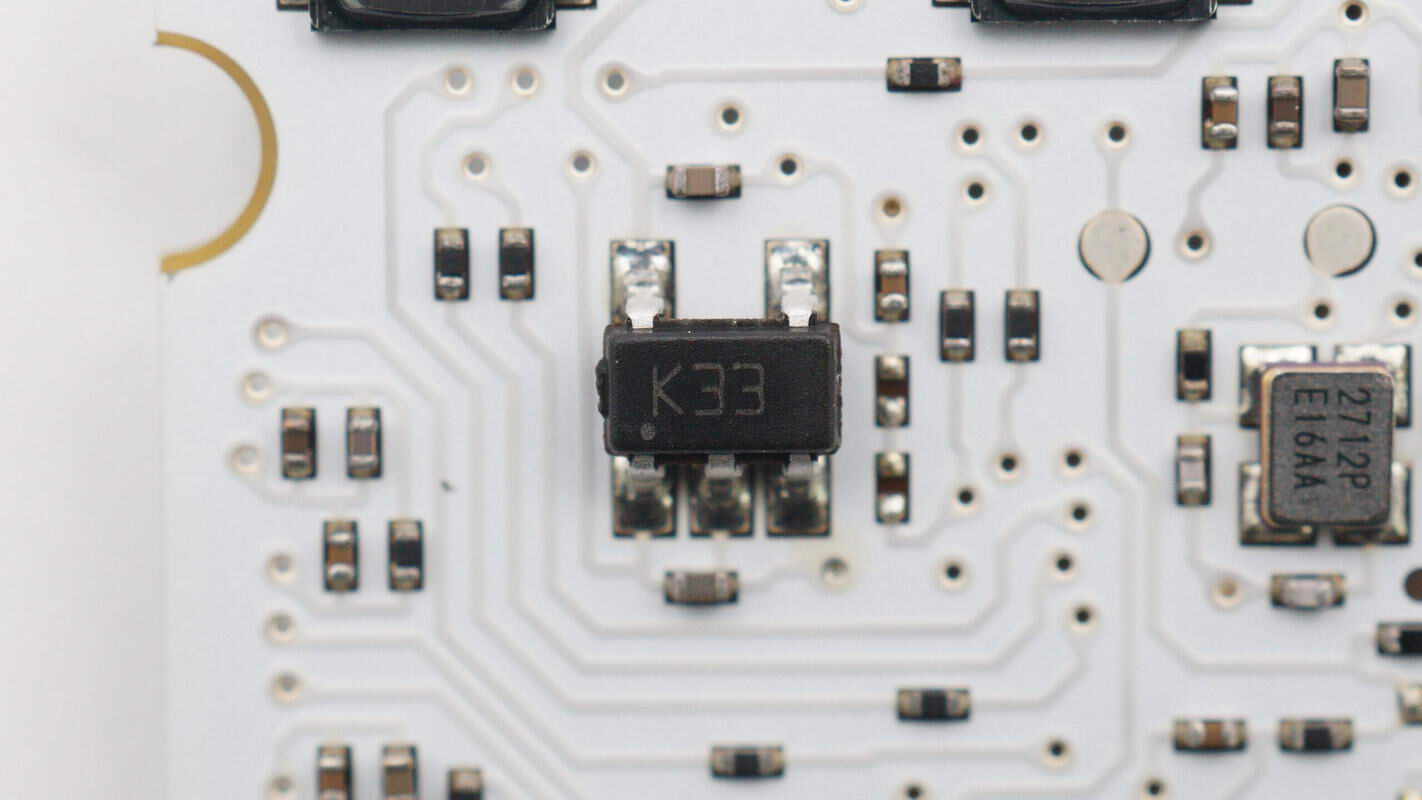
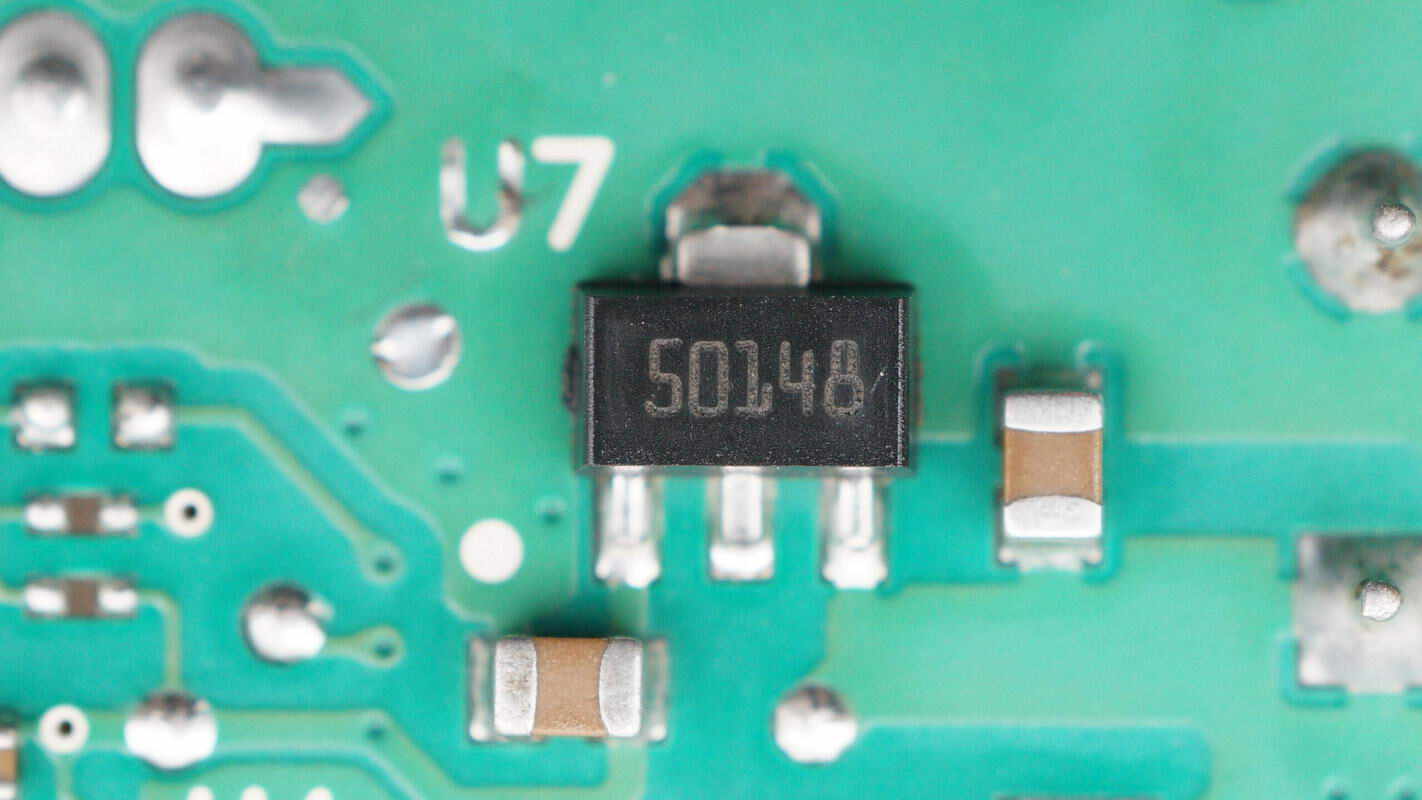
The voltage regulator chip is from STMicroelectronics, marked with K33, model LDK130M33R. It is an ultra-low noise regulator supporting a 5.5V input voltage, with a 3.3V output voltage and 300mA output current, housed in a SOT23-5L package.
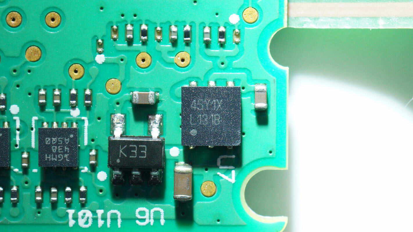
Close-up of the chip marked with "45Y1X."
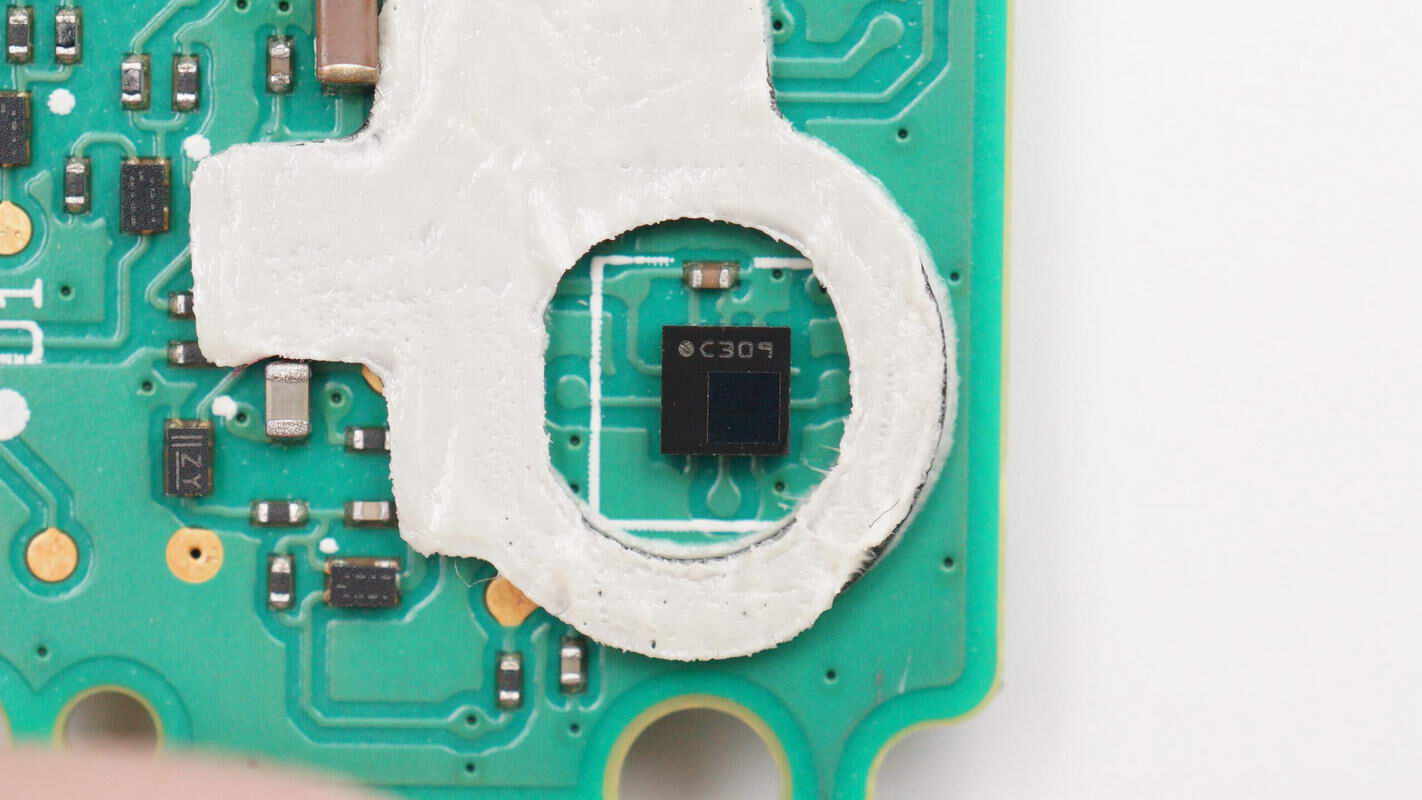
Close-up of the digital barometer chip.
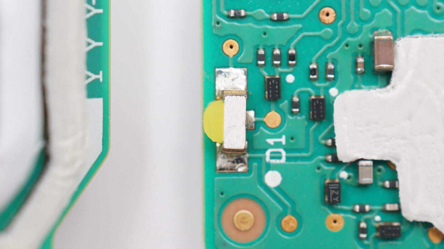
Close-up of the white SMD LED, used to indicate filter abnormalities.
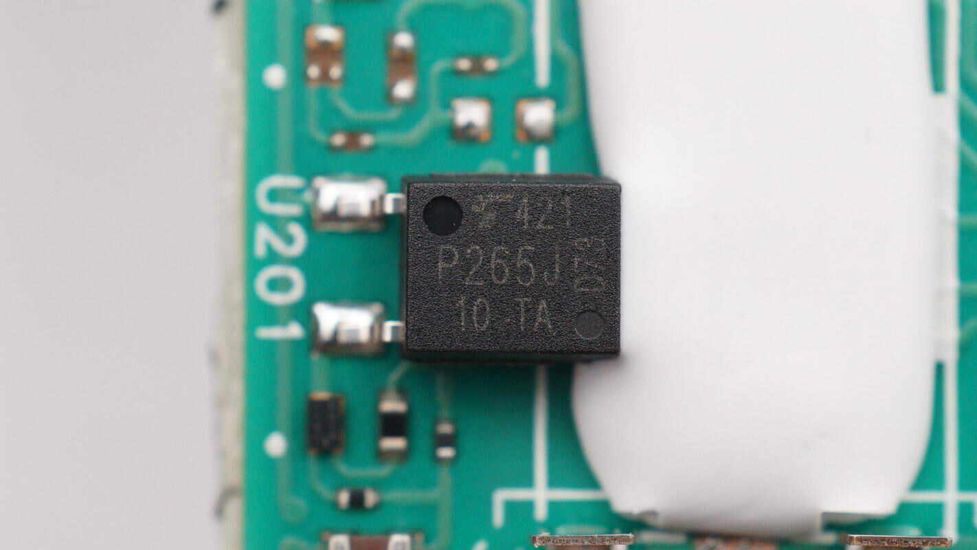
The SMD optocoupler is from Toshiba, model TLP265J, and is used to drive the thyristors.
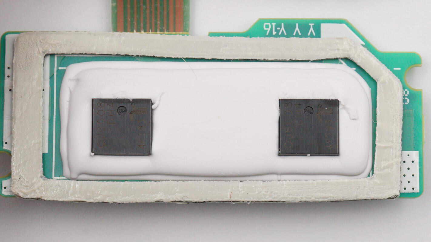
The two thyristors are sealed with adhesive and are attached to the air inlet using double-sided tape to dissipate heat using airflow.
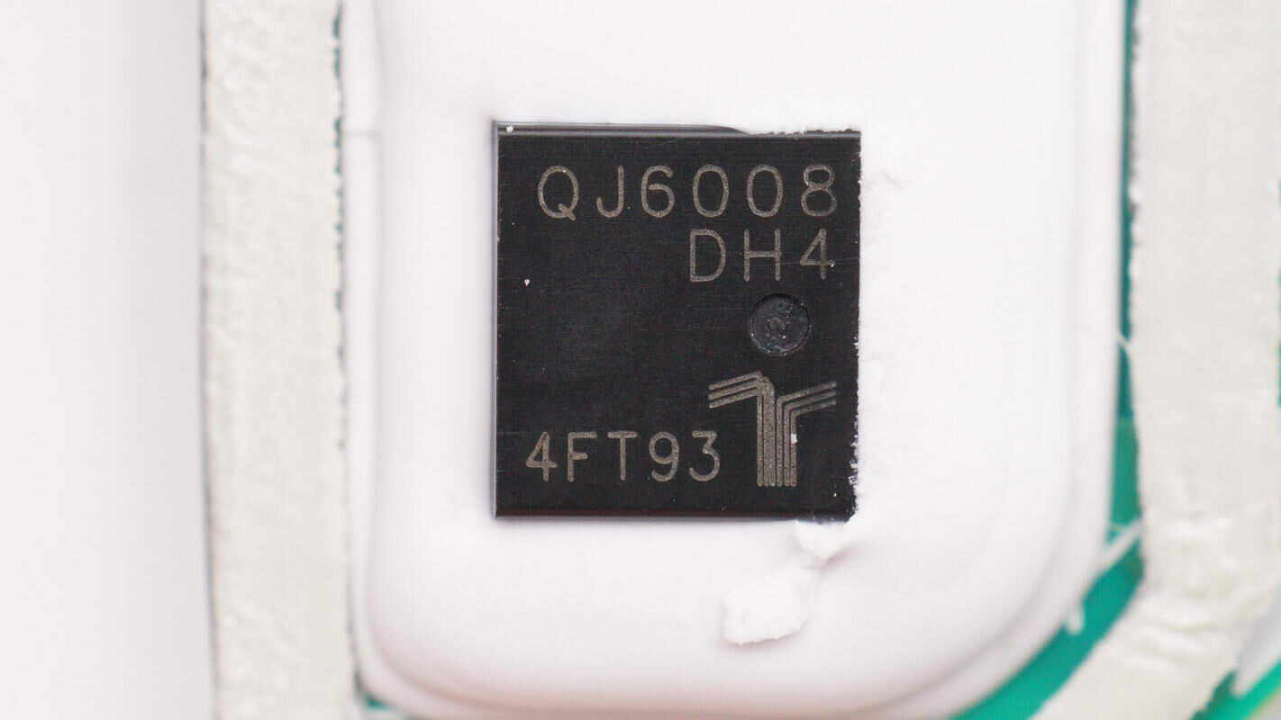
The thyristor is from Littelfuse, model QJ6008DH4, with specifications of 8A 600V and uses a TO-252 package.
Remove the PCB with the buttons.
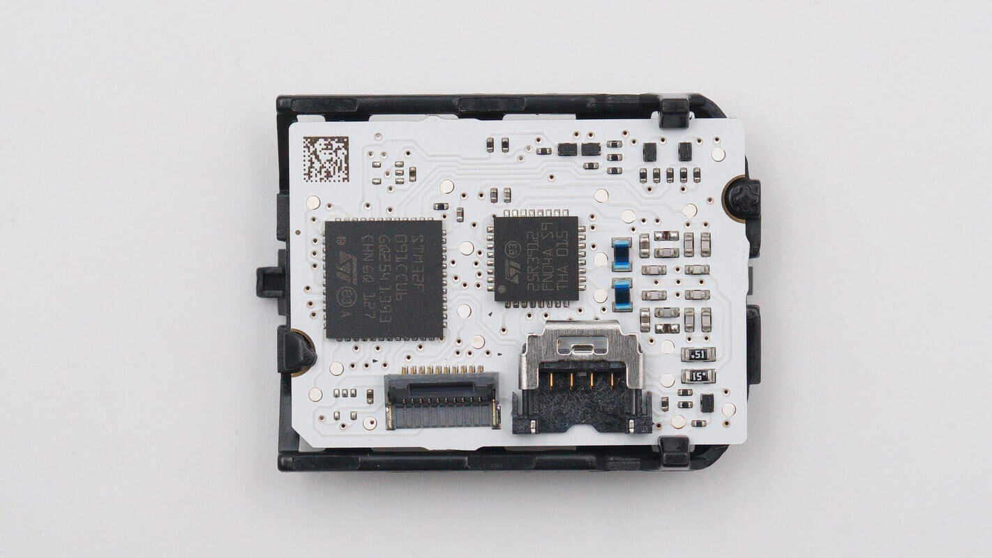
There are two chips and connectors on the back.
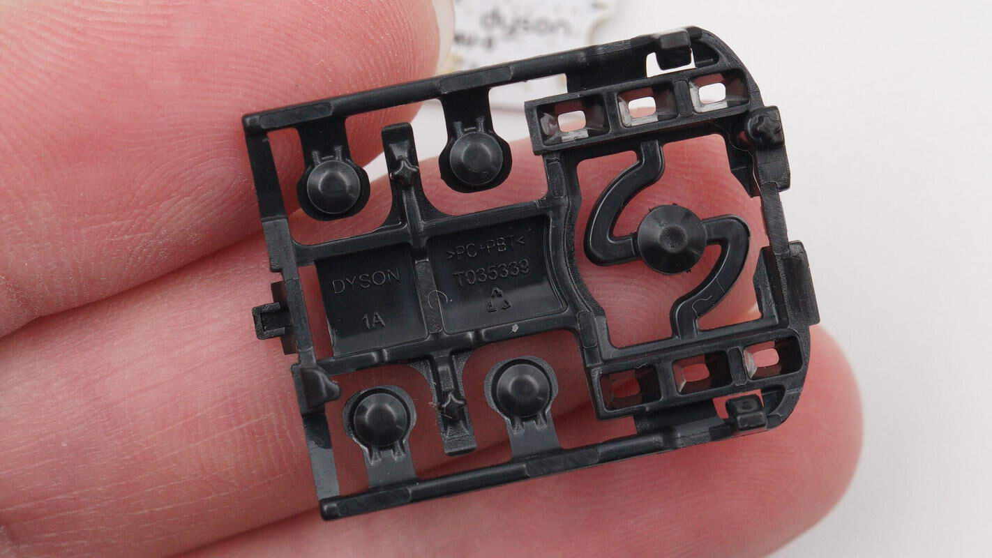
Remove the front button bracket.
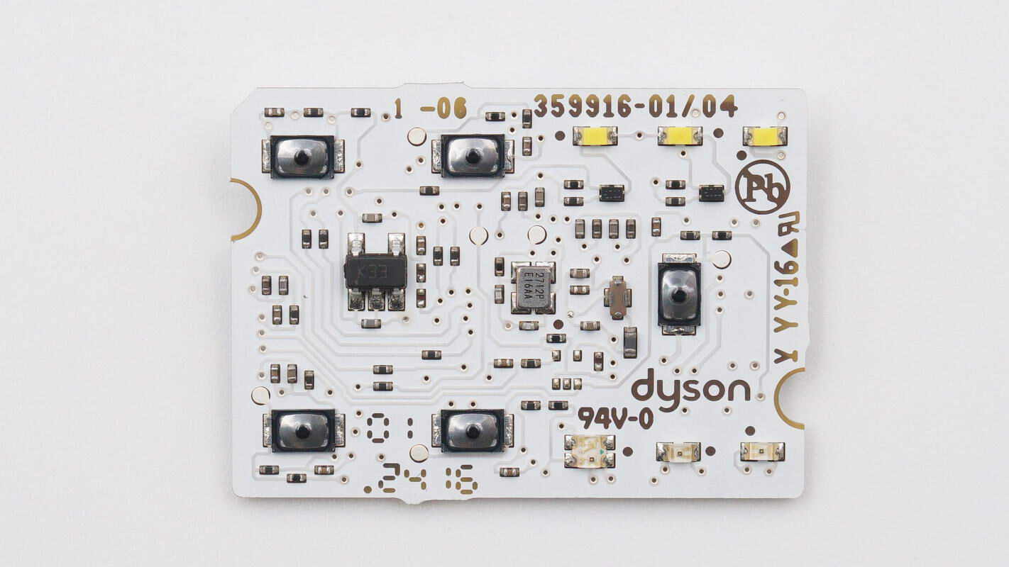
There are SMD buttons, LED indicators, a voltage regulator chip, and a crystal oscillator on the front.
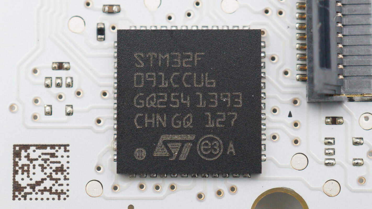
The MCU is from STMicro, model STM32F091CCU6. It features an ARM Cortex-M0 core running at 48 MHz, with 256 KB of Flash and 32 KB of SRAM, and comes in a UFQFPN48 package.
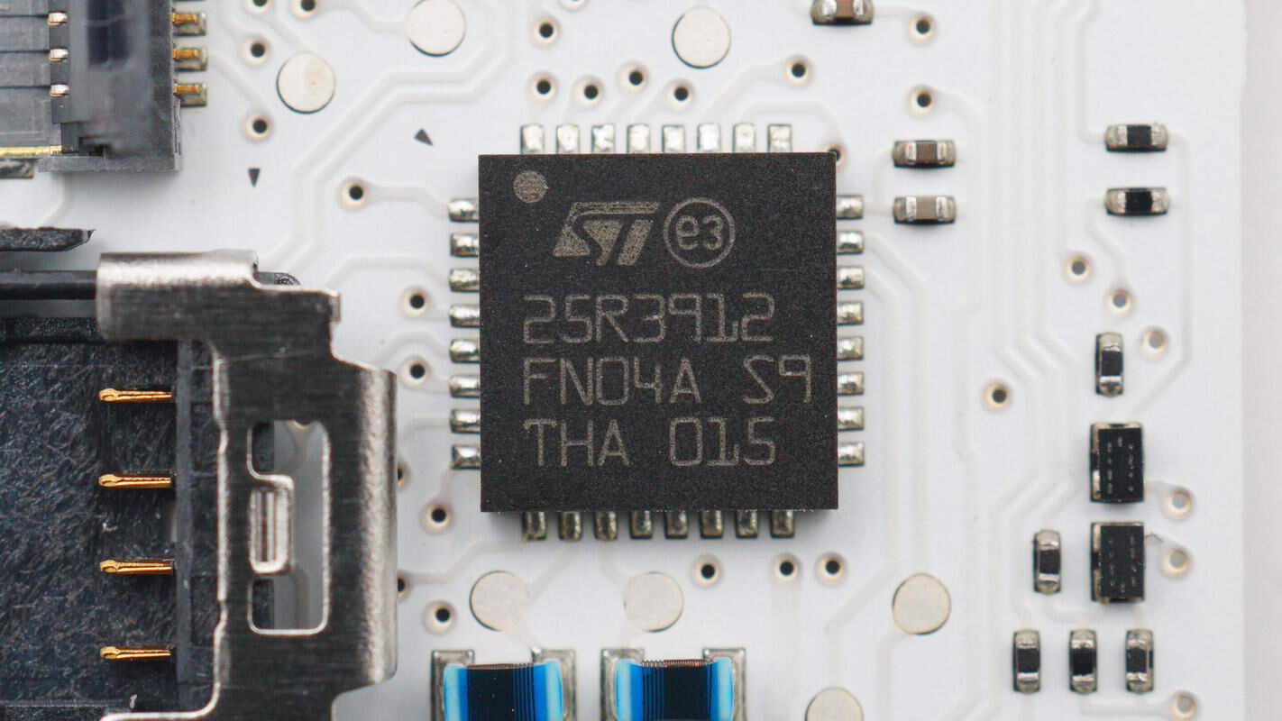
The RFID chip is from STMicroelectronics, model ST25R3912. It is a high-performance NFC/HF RFID reader/writer chip with an integrated differential antenna driver, housed in a VFQFPN32 package.
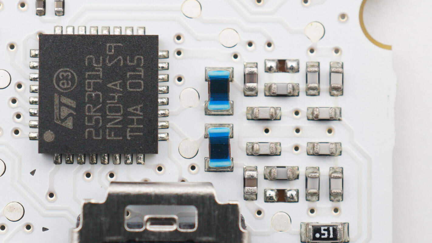
Close-up of the two wire-wound inductors at the output end.
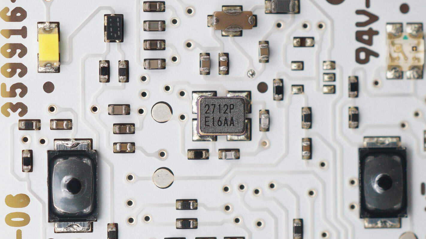
Close-up of the external clock crystal oscillator.
Close-up of the STMicro LDK130M33R voltage regulator chip.
Close-up of the SMD button.
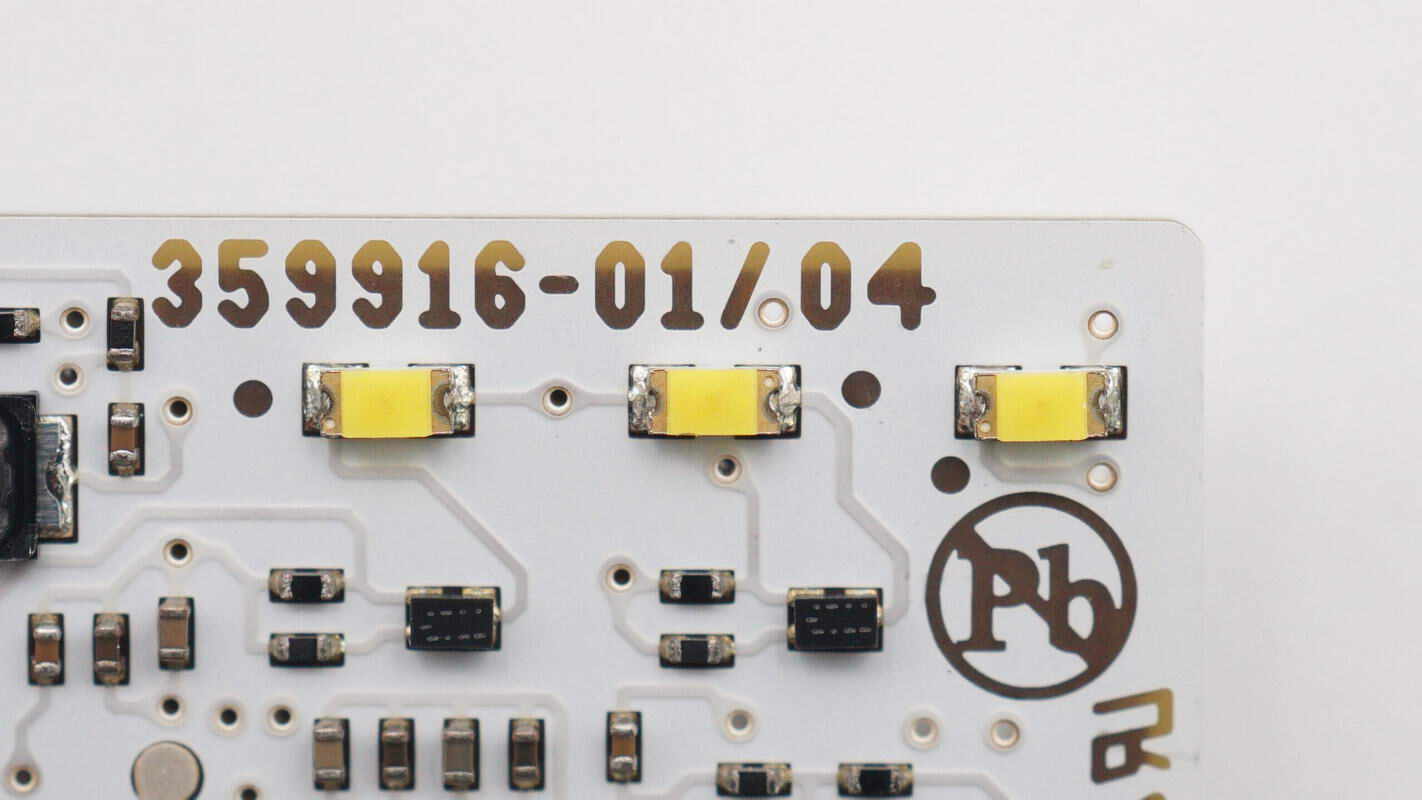
Close-up of the three LEDs used for fan speed indication.
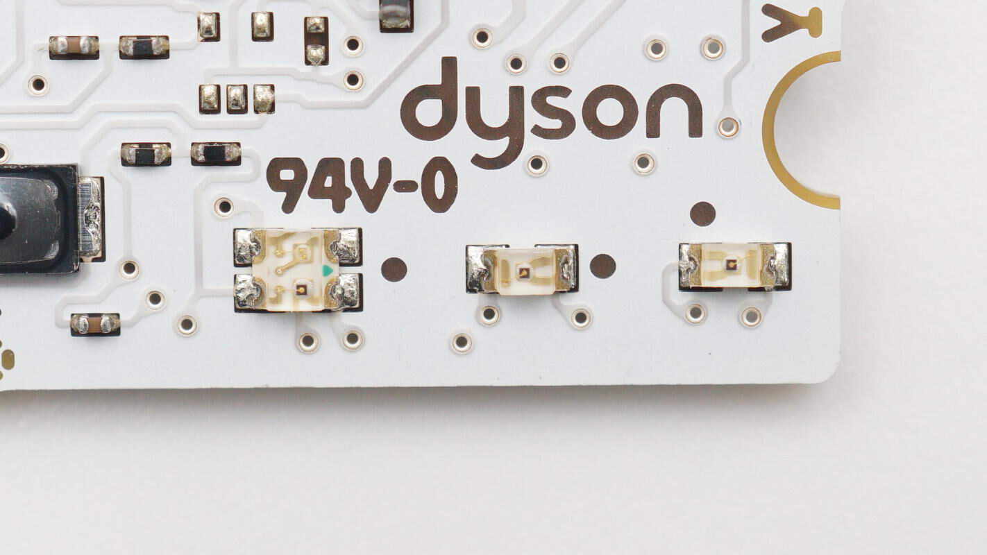
Close-up of the three LEDs used for temperature indication.
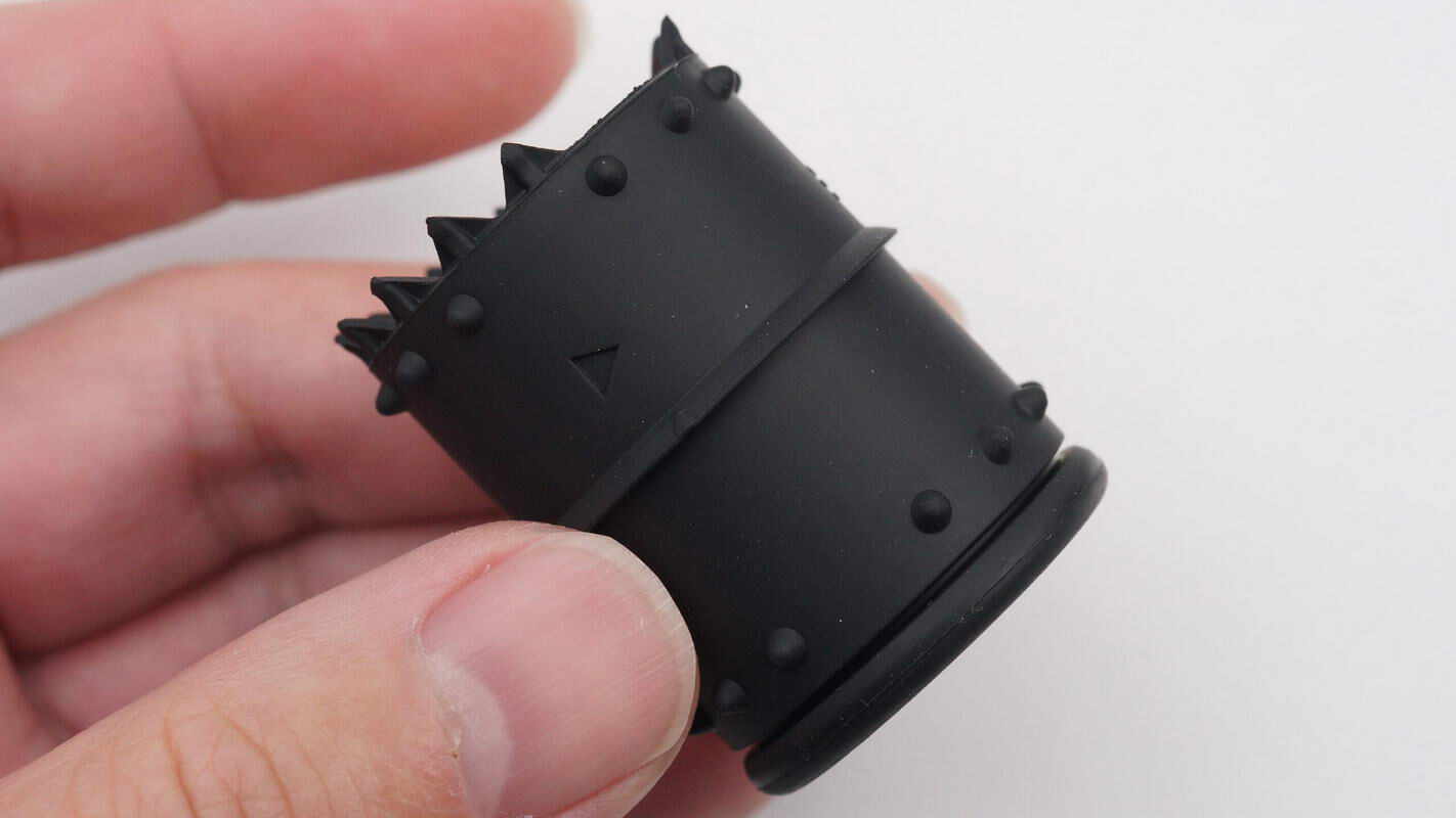
The motor sleeve’s rubber cover features a sealing ring and shock-absorbing protrusions.
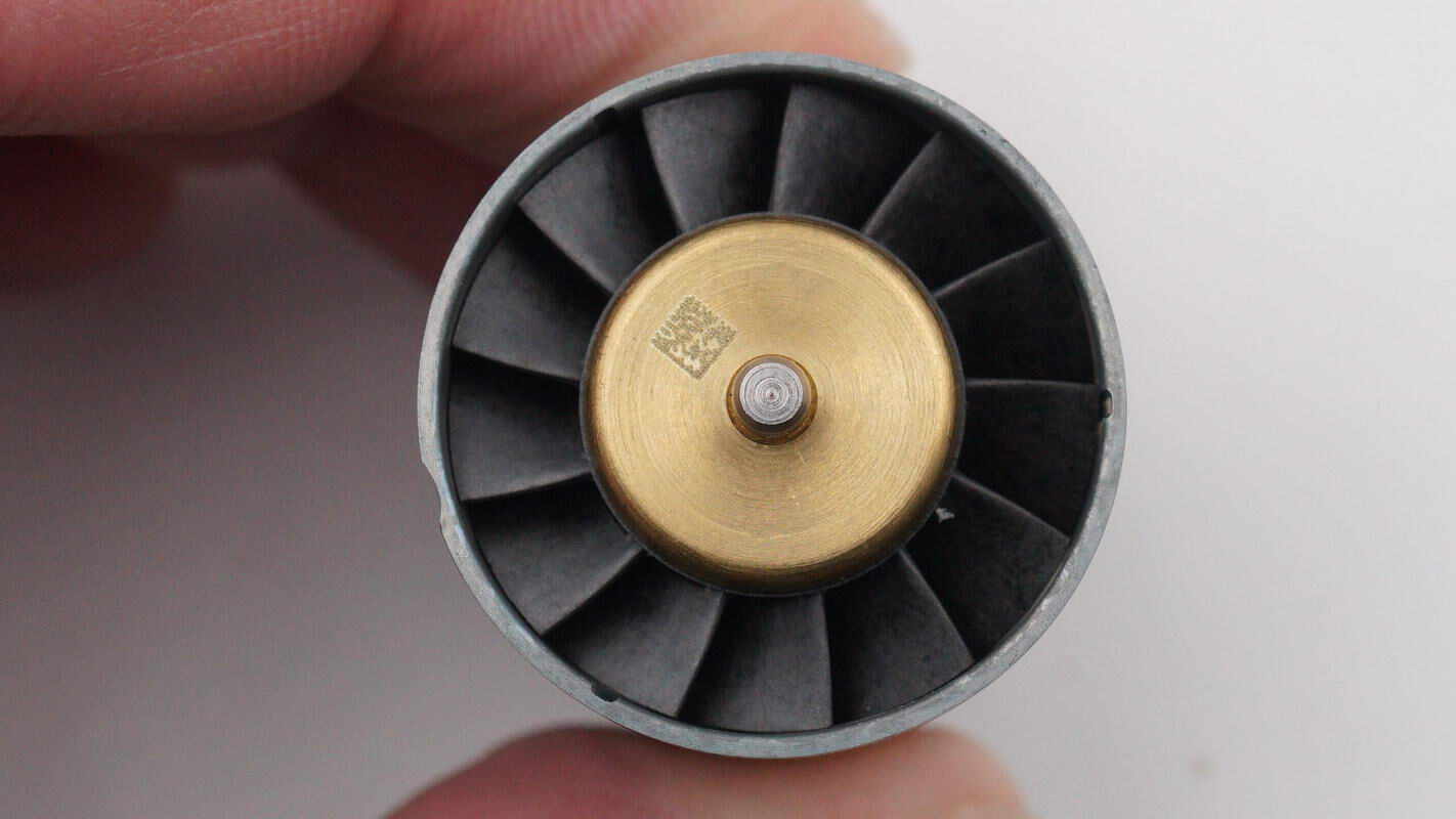
The front fan of the motor has 13 blades.
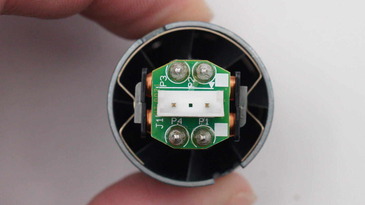
The rear of the motor features a PCB and a connection socket.
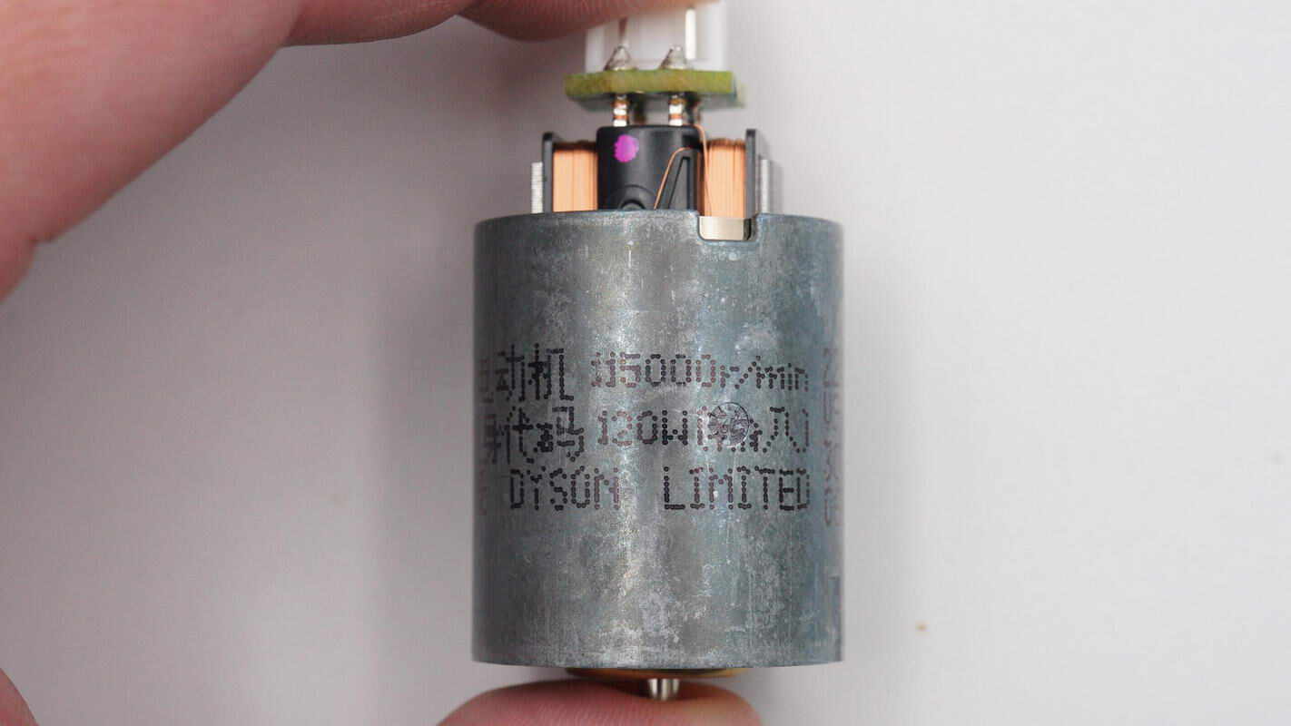
Brushless DC Motor
115,000 r/min
120W (input)
85W (output)
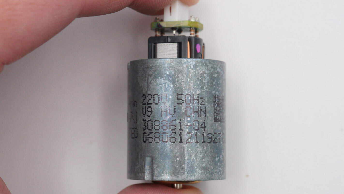
The motor is labeled: 220V 50Hz V9 HV.
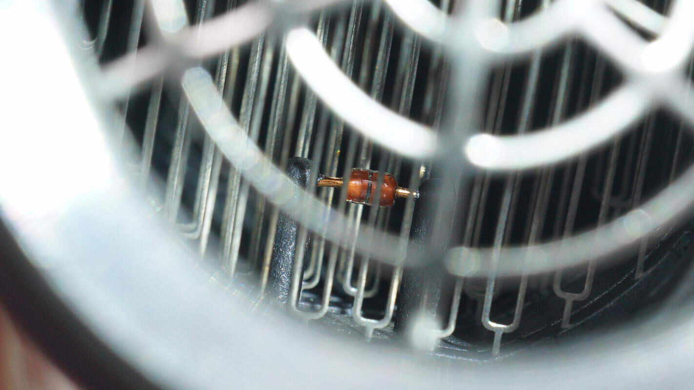
A thermistor is built into the air outlet to monitor the air temperature.
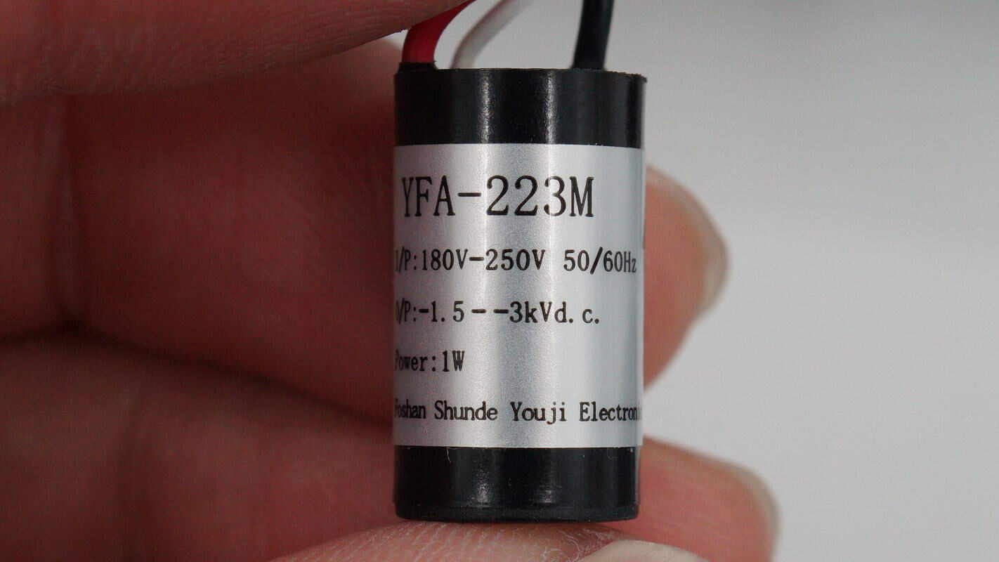
The ion generator is from Youki Electronics, model YFA-223M. It supports 180–250V AC input, with an output voltage of -1.5 to -3kV, and a power rating of 1W.
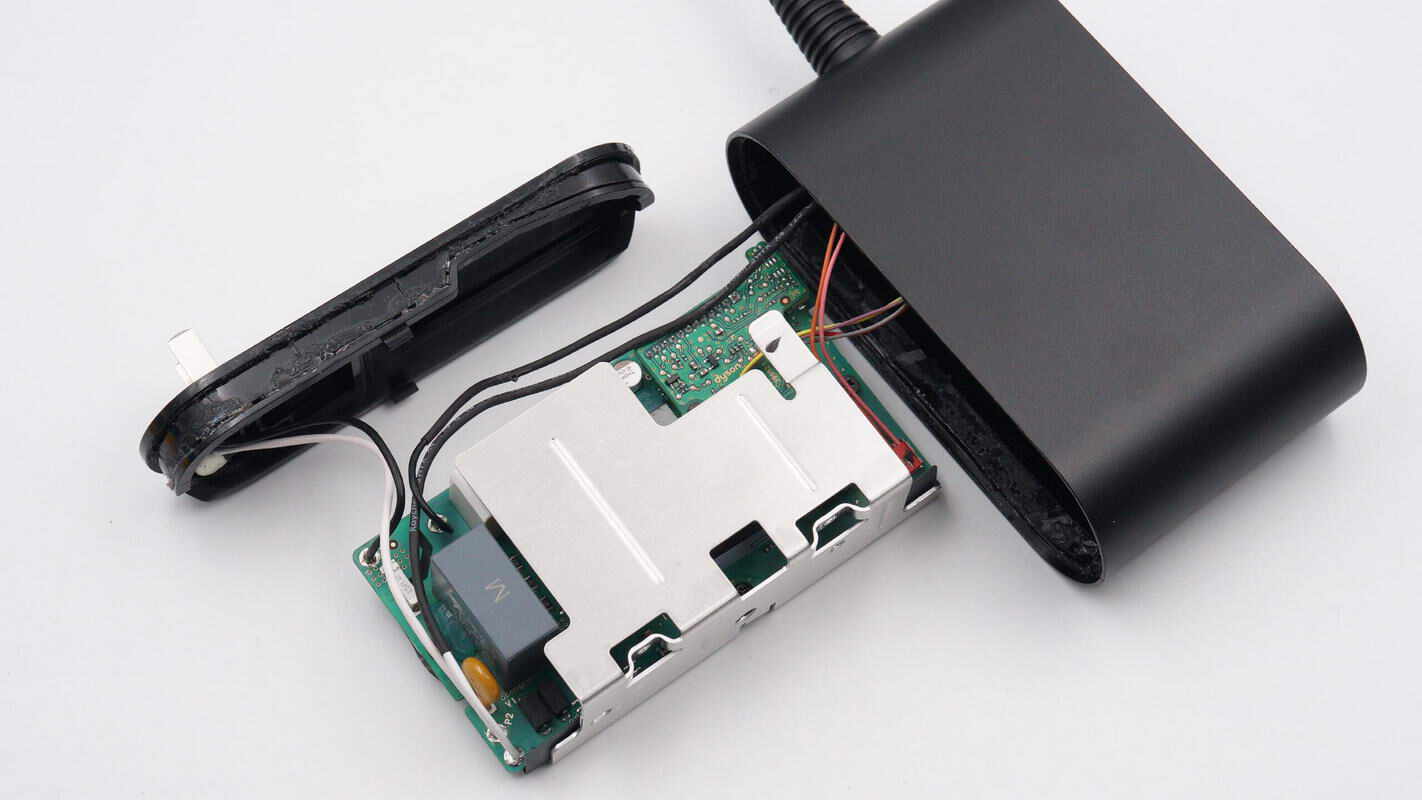
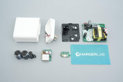
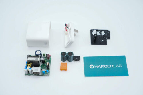
Open the plug casing to reveal the PCBA module, which is enclosed in an aluminum alloy heat sink.
Unscrew the screws and remove the heat sink. The heating element of the PCBA module is attached with thermal pads.
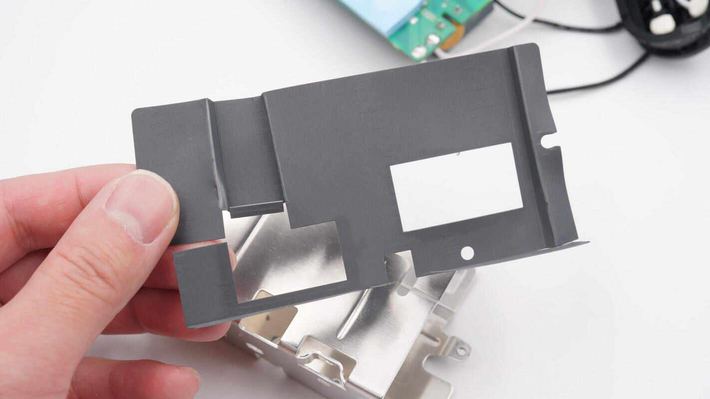
There are openings on the Mylar sheet corresponding to the position of the thermal pads.
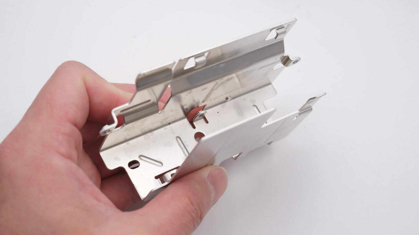
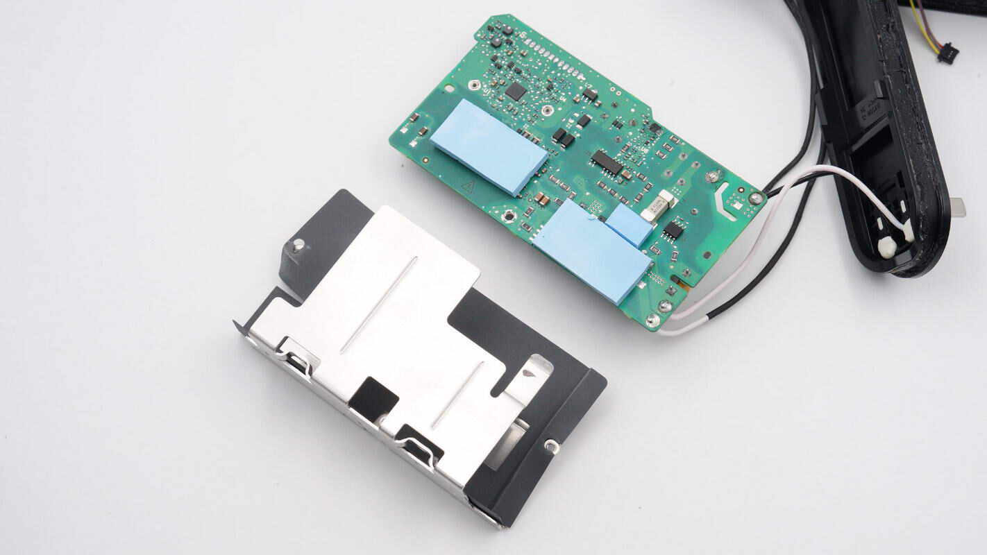
The heat sink has a U-shaped structure.
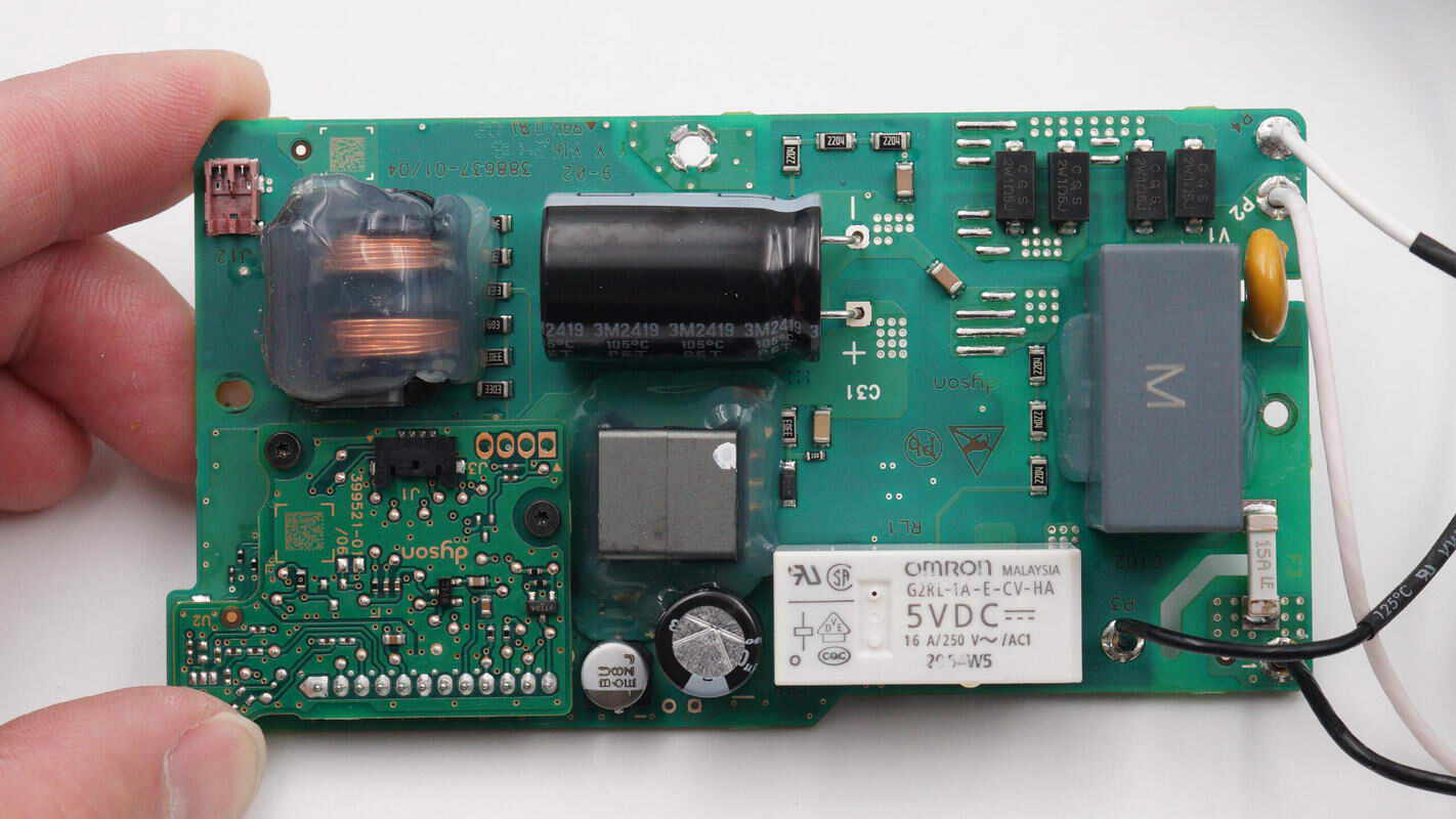
On the right side of the PCBA module is the AC input section, which includes fuses, a varistor, chip resistors, a safety X2 capacitor, and a relay. In the middle, there are high-voltage filter capacitors and a transformer.
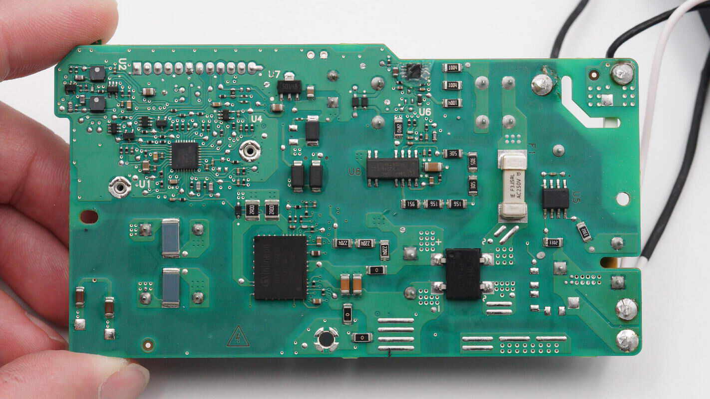
On the back side, there are a fuse, X capacitor discharge chip, bridge rectifier, switching power supply chip, and an intelligent power module.
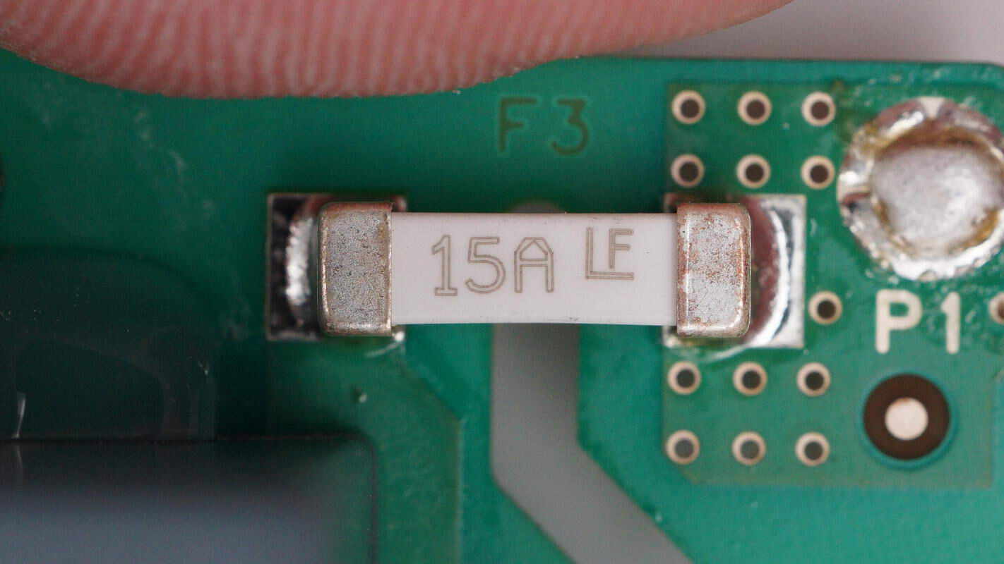
The input fuse is from Littelfuse. 15A.
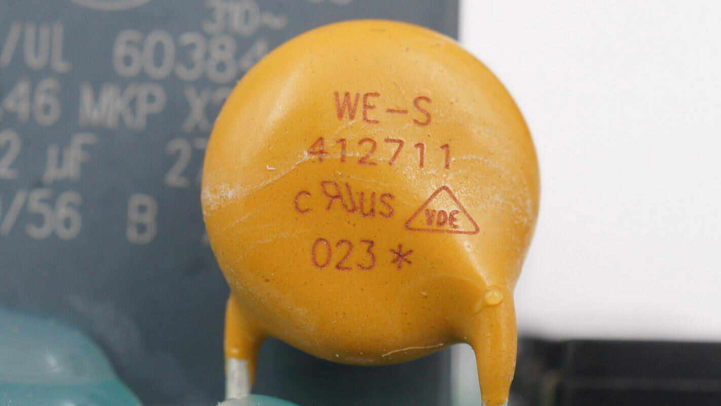
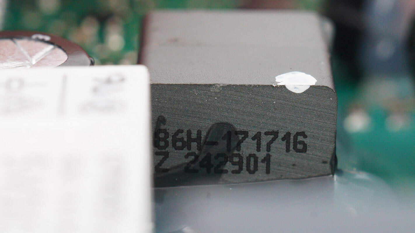
The varistor is from WE, model 820412711, with an operating voltage of 275V, and is used to absorb overvoltage surges.
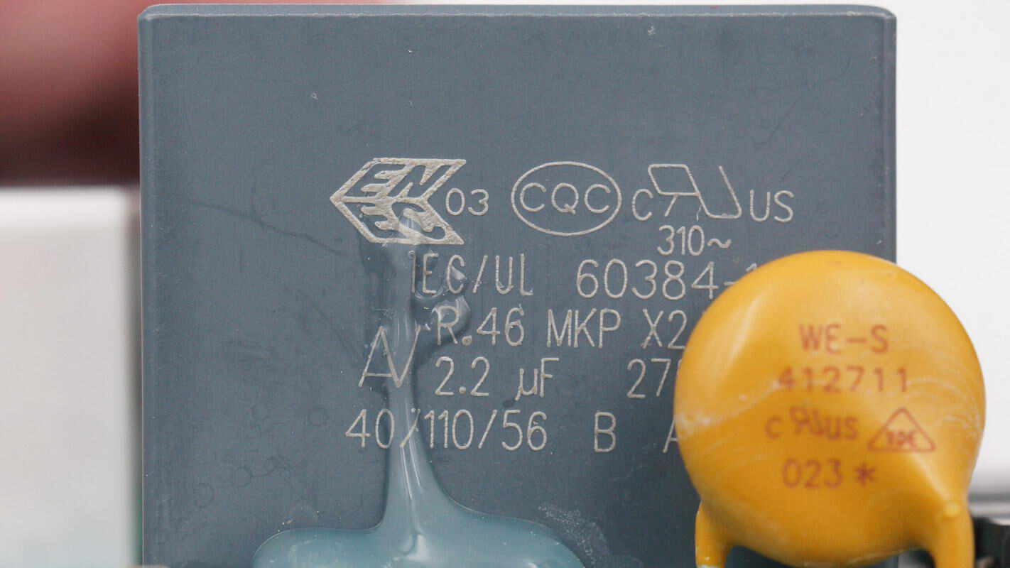
The safety X2 capacitor is from KEMET. 2.2μF.
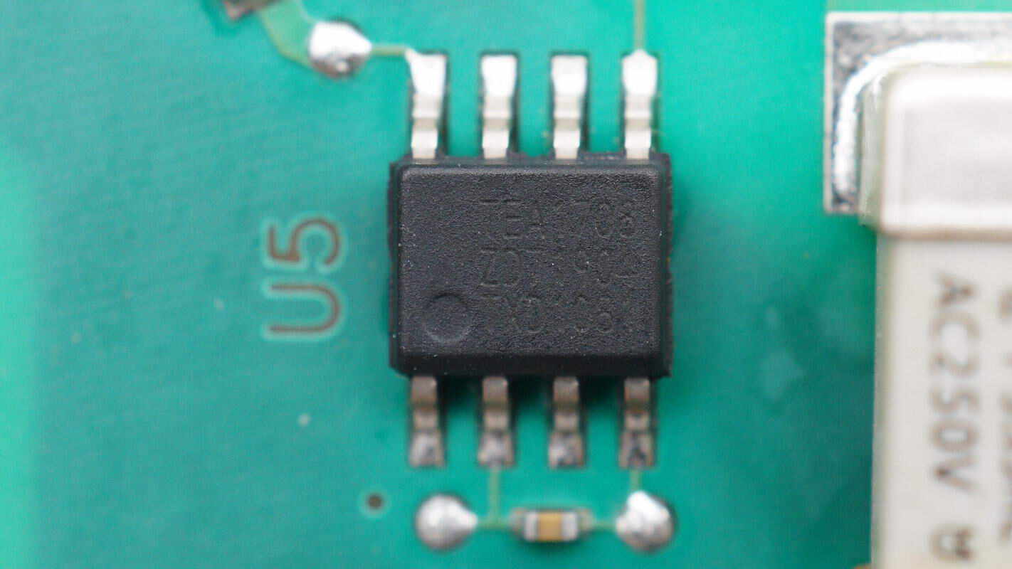
The discharge chip is from NXP, model TEA1708T, which is used for automatic discharge of X capacitors. It has a typical power consumption of 1mW and uses an SO8 package.
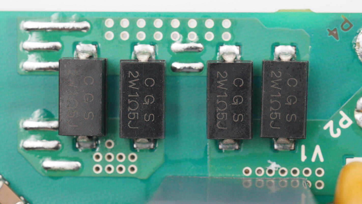
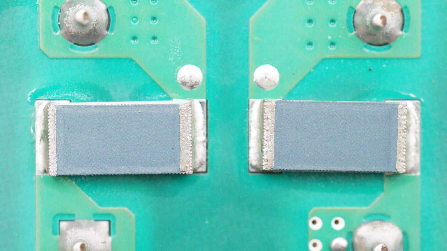
The four SMD resistors are from TE, which are wirewound resistors with a resistance of 1.5Ω and a power of 2W.
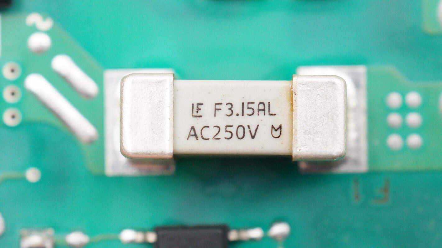
The other fuse is also from Littelfuse. 3.15A 250V.
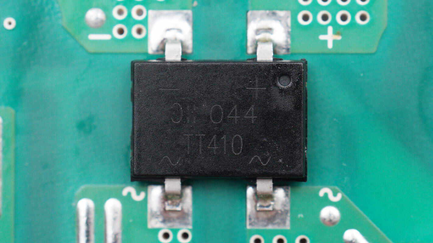
The bridge rectifier is from DIODES, model TT410, with specifications of 4A 1000V and uses TT package.
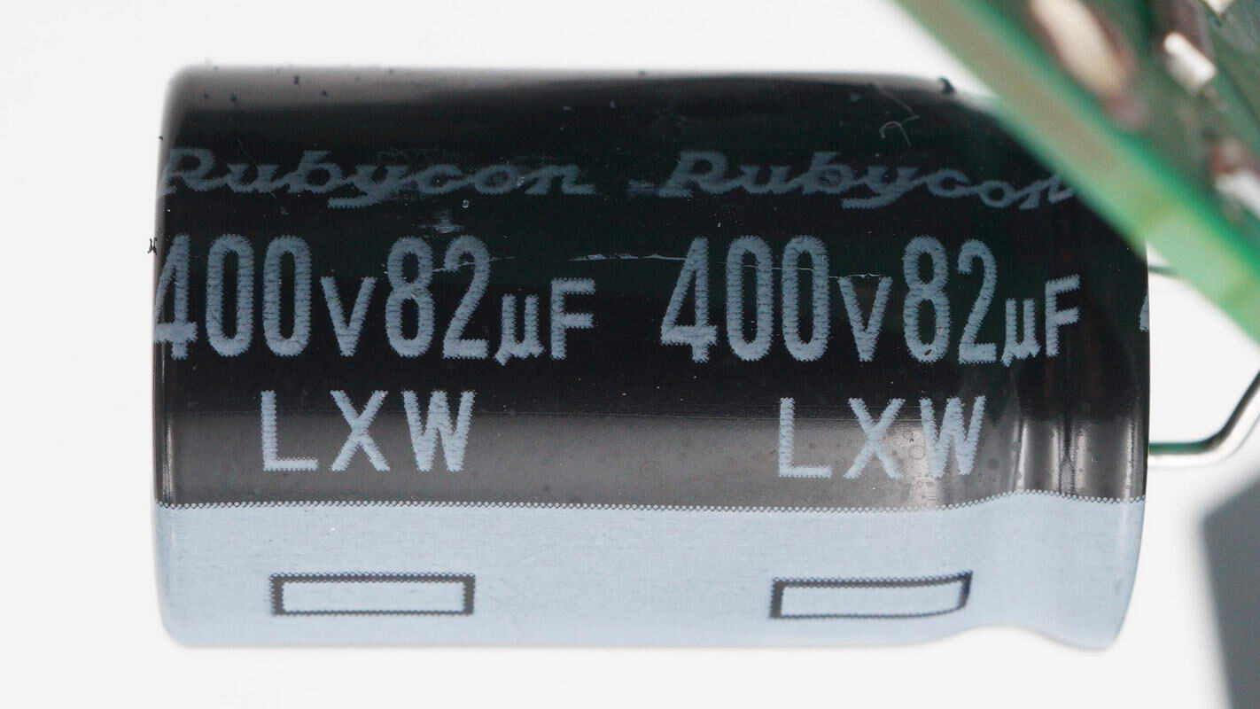
The high-voltage filter capacitor is from Rubycon. 400V 82μF.
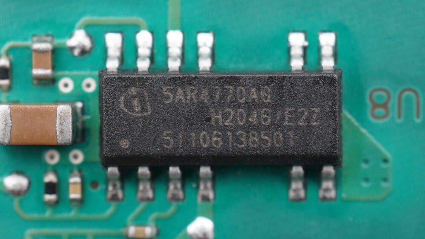
The switching power supply chip is from Infineon, model ICE5AR4770AG. It integrates a 700V MOSFET internally, features digital soft-start, cycle-by-cycle peak current limiting, and comprehensive protection functions, and comes in a DSO-12 package.
The transformer is secured with adhesive for reinforcement.
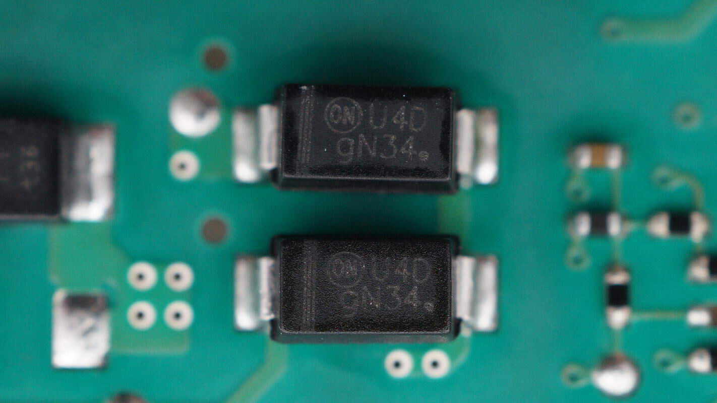
The rectifiers are from Onsemi, marked with U4D, model MURA120T3G, specification is 1A 200V, and use SMA package.
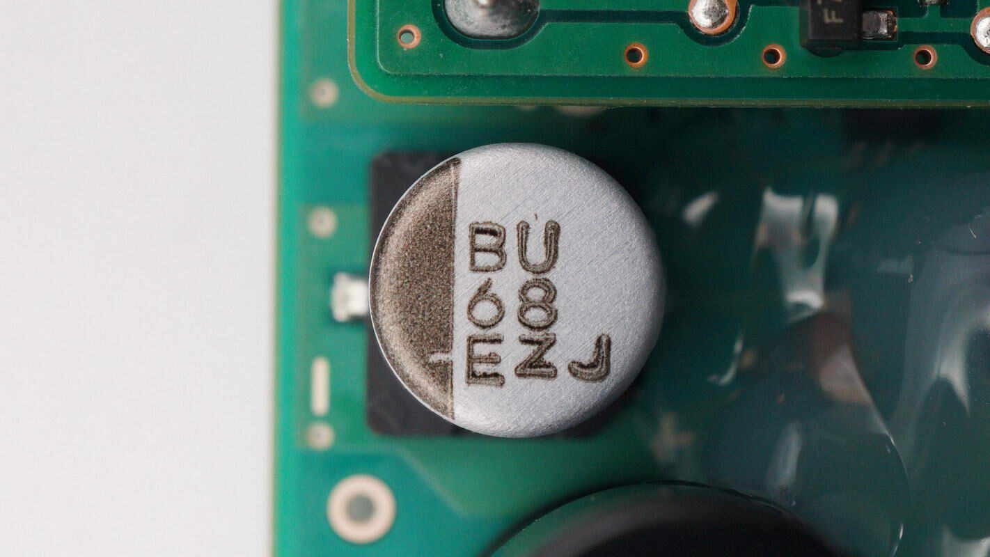
The filter capacitor specification is 68μF 25V.
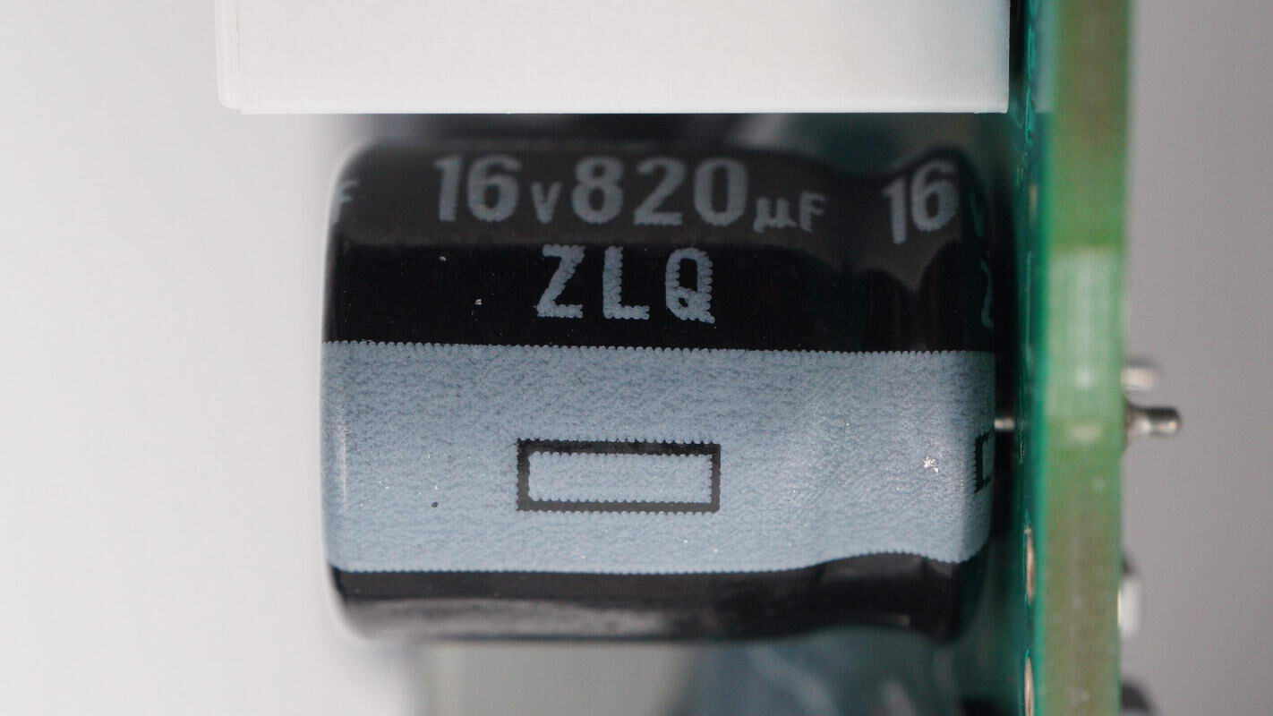
The other filter capacitor is from Rubycon and has a specification of 16V 820μF.
The voltage regulator chip is from STMicroelectronics, model LDK220U50R. It supports a 13.2V input voltage, outputs 5V at 200mA, and comes in a SOT-89 package.
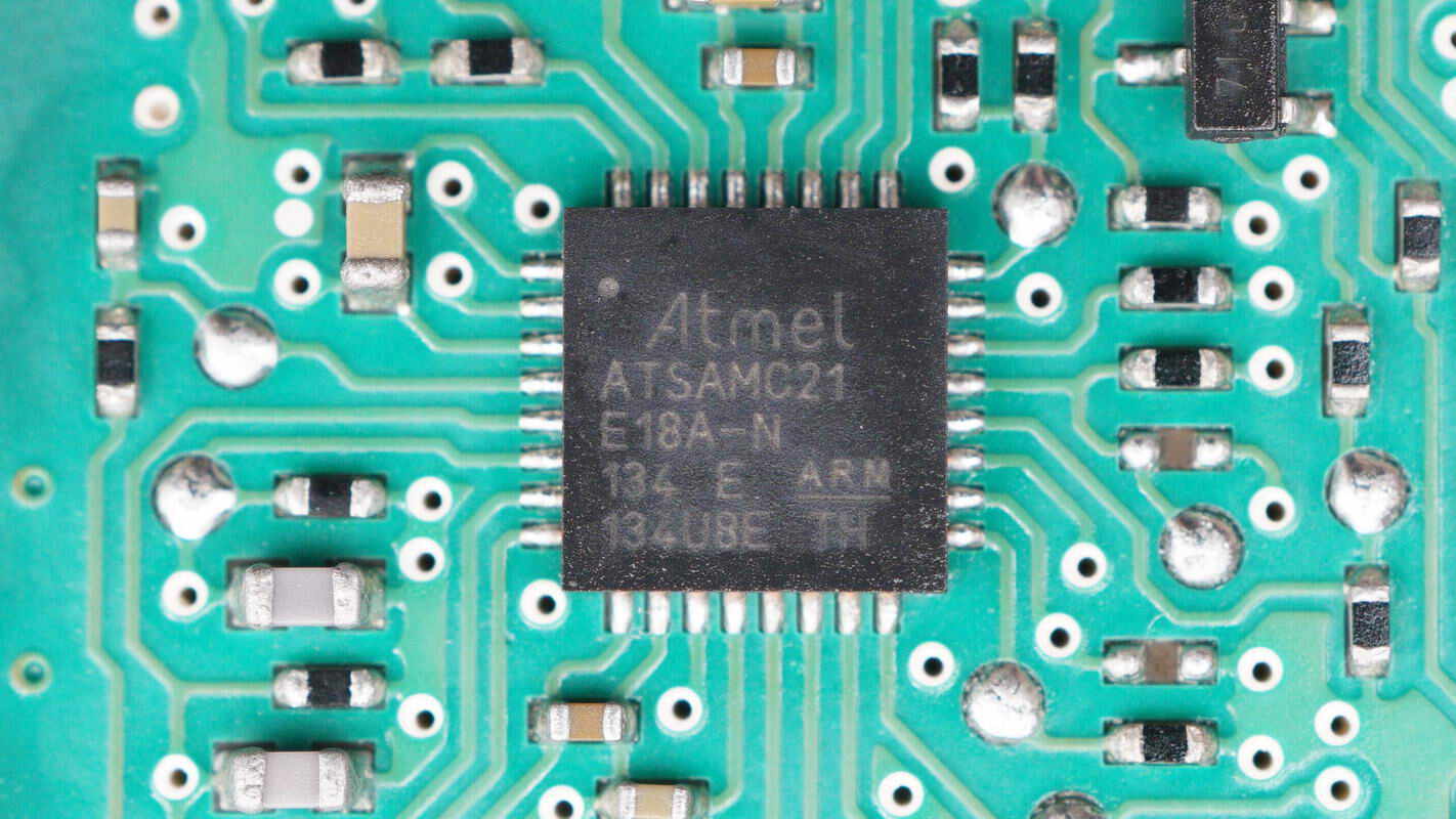
The MCU used to drive the motor is from Microchip, model ATSAMC21E18A-N. It is a 32-bit Cortex-M0+ MCU operating at 5V, with 256KB Flash and 32KB SRAM, housed in a 32-pin VQFN package.
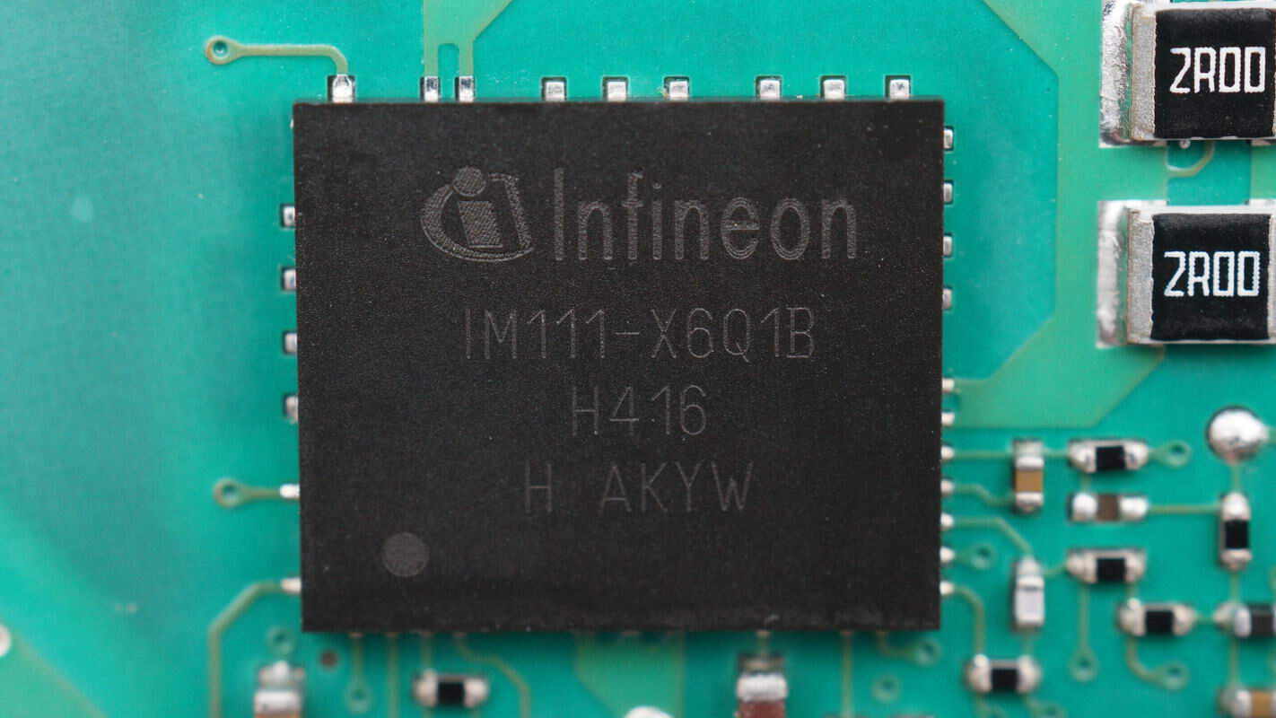
The intelligent power module is from Infineon, model IM111-X6Q1B. It is an integrated H-bridge driver chip featuring a 600V-rated CoolMOS with 280mΩ on-resistance. It includes overcurrent protection and fault reporting, undervoltage lockout, and shoot-through protection. The module supports 3.3V input and motor drives from 80W to 200W, with 1500V RMS isolation capability. It comes in a 12×10 mm QFN package.
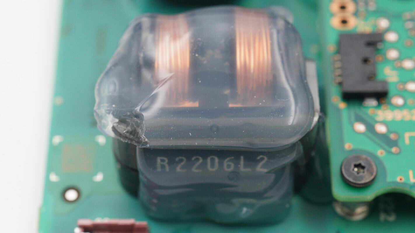
The output filter inductor is reinforced with adhesive.
Close-up of two SMD resistors.
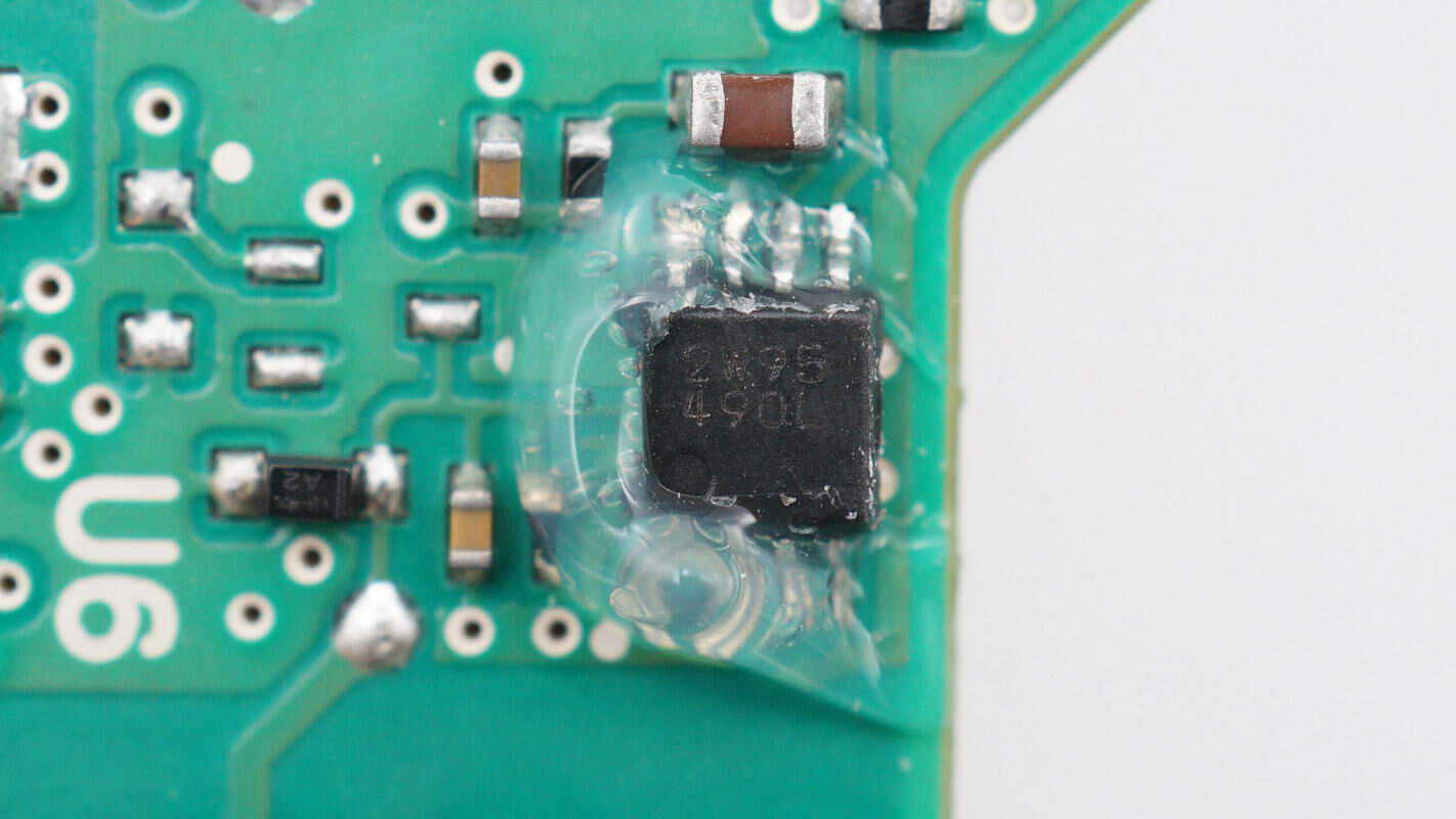
A close-up of the chip marked with 2W95490L.
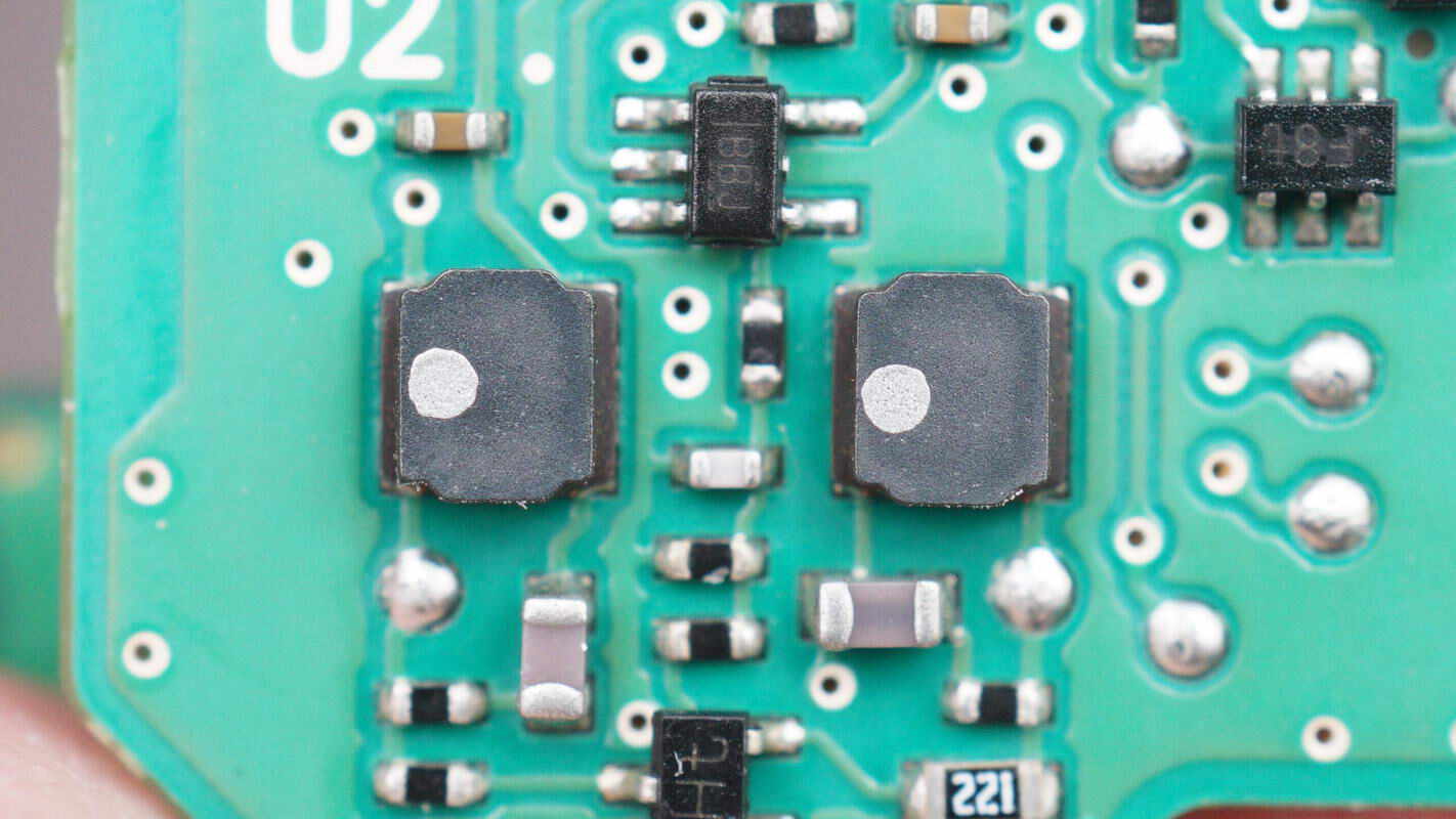
These two SMD inductors are used for output filtering.
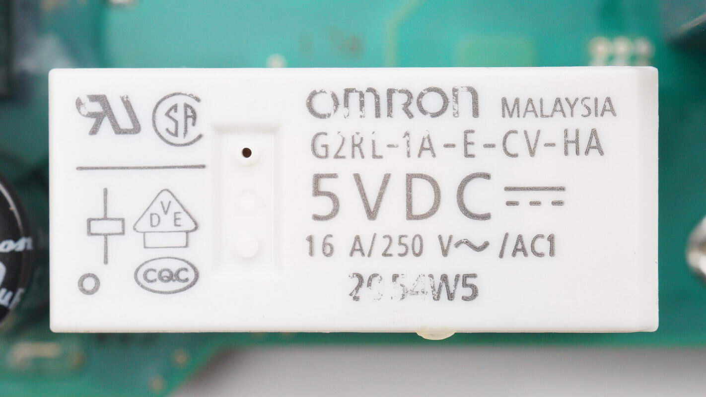
The relay used for power control is from OMRON, model G2RL-1A-E-CV-HA. It has a coil voltage of 5V and a contact rating of 16A at 250V.
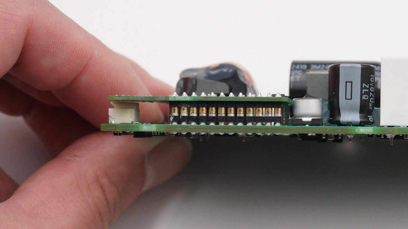
The PCBs are connected via pin headers.
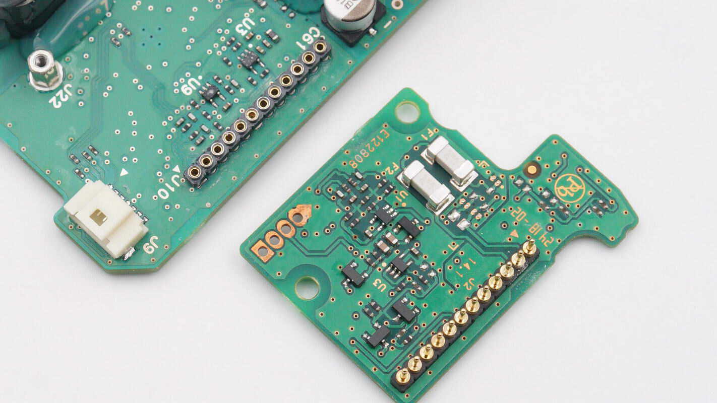
There are two SMD fuses on the back of the small PCB.
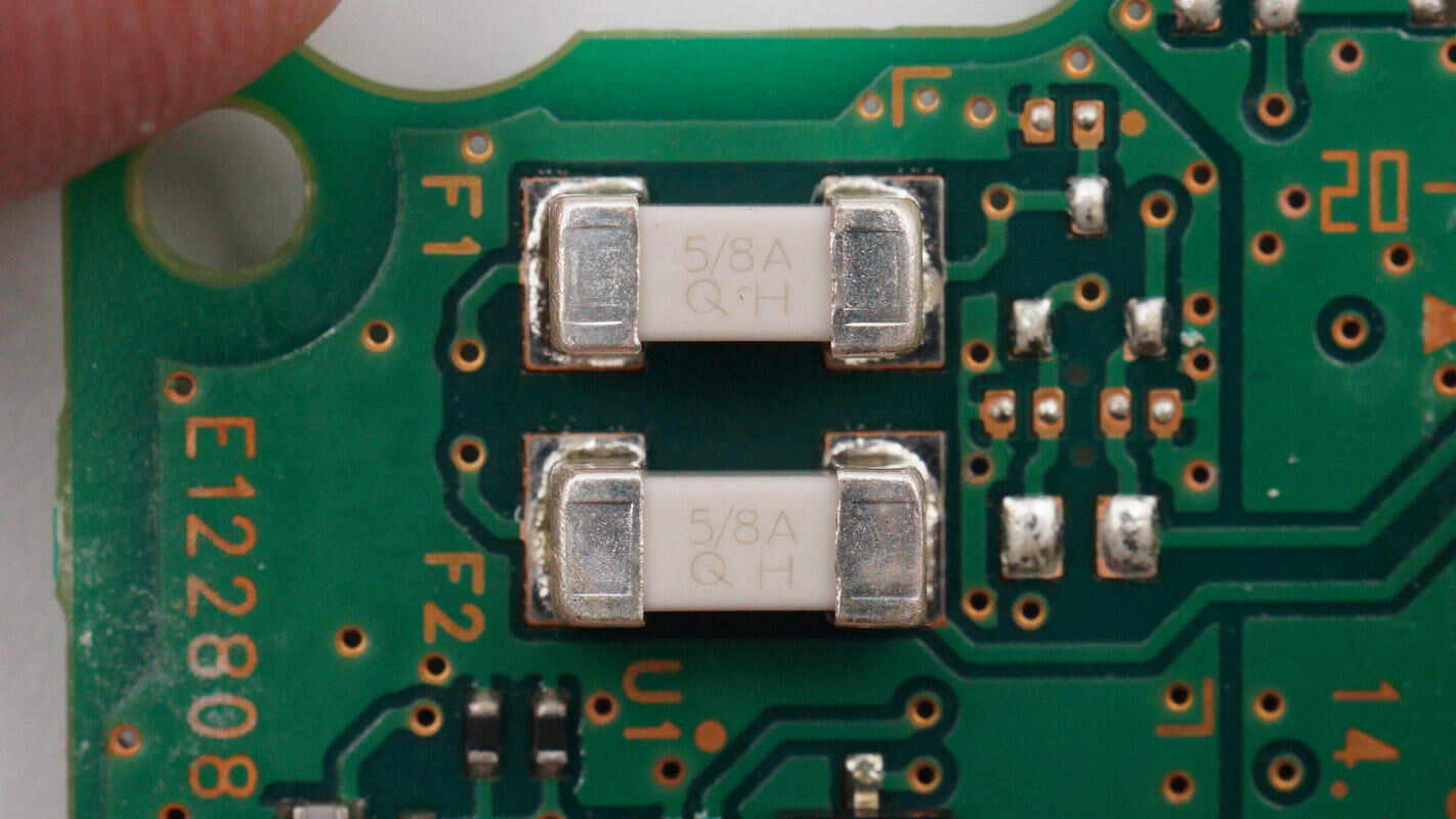
Close-up of the SMD fuses.
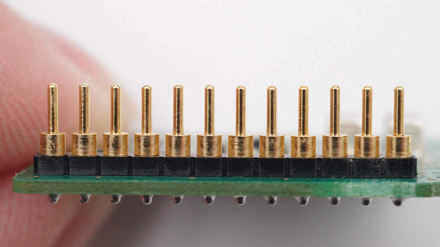
Close-up of the gold-plated pins.
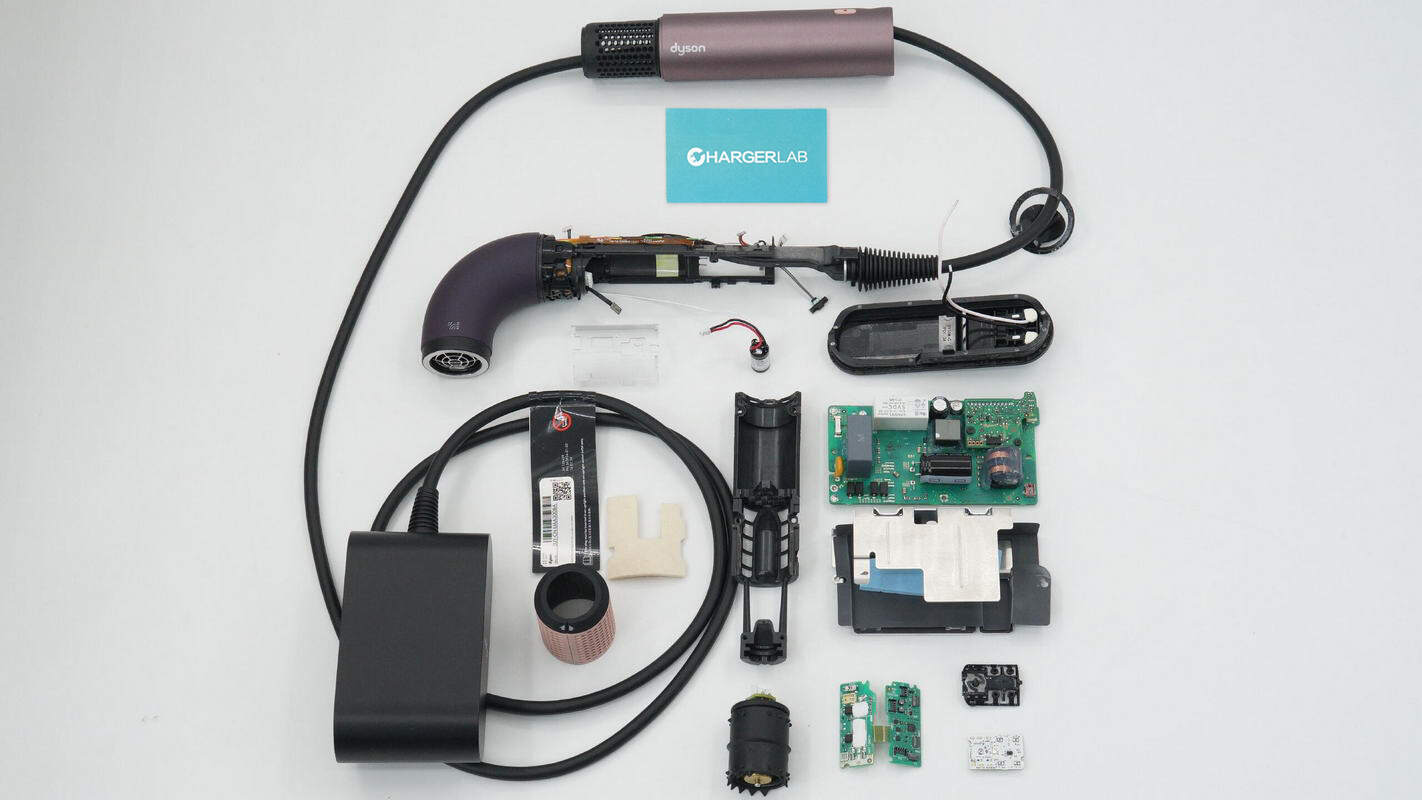
Well, those are all components of the Dyson Supersonic r 1700W hair dryer.
Summary of ChargerLAB
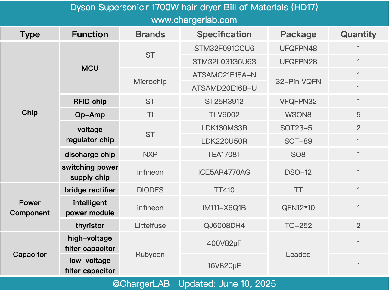
Here is the component list of the Dyson Supersonic r 1700W hair dryer for your convenience.
It features a brand-new R-shaped body design combined with ergonomic engineering for flexible and convenient operation. Utilizing streamlined airflow heating technology, it evenly heats the airflow. Equipped with five magnetic smart nozzles to meet styling needs, it also includes a one-touch cold air button.
After taking it apart, we found that it uses a split design, relocating the motor drive circuit out of the handle to achieve a compact body. The motor drive circuit and standby power supply are housed in the adapter. It employs an Infineon switching power supply chip and an intelligent power module, with the master control MCU from Microchip, and includes a relay for power control.
The thyristors that control the heating element are located inside the air inlet, cooled by the airflow. Inside the air inlet, there is also a pressure sensor that, together with a sensor at the bottom of the handle, detects whether the filter is properly installed. The nozzle, as an integral part, uses RFID technology to detect its installation status, ensuring proper operation.
Related Articles:
1. Teardown of Delta 300W Triple USB-C AC/DC Power Adapter (ADP-300EB B)
2. Teardown of HONOR 100W GaN Charger for Laptop (HN-200500CP0)
3. Teardown of UGREEN Nexode 65W Charger with Retractable USB-C Cable (X605)