Introduction
Apple released the iPhone Air at its Fall 2025 event. This new device features a 6.5-inch display and an ultra-thin 5.6mm chassis, made possible by a highly compact internal layout. To achieve this slim profile, the iPhone Air uses a 3,149mAh battery, which is relatively small by modern standards.
To compensate for the limited battery capacity, Apple introduced a MagSafe Battery Pack tailored specifically for the iPhone Air. Model A3466 connects via MagSafe and extends video playback time from 27 hours to 40 hours. The pack contains a 3,149mAh lithium battery—matching the phone’s internal capacity—and provides up to 65% additional battery life. It includes a USB-C port that supports 9V/3A input and 5V/1.5A output for charging.
Now available from Apple at $99.00, this accessory is designed for users who want extra power without compromising portability. The following teardown examines the internal structure and components used in the A3466 battery pack.
Product Appearance
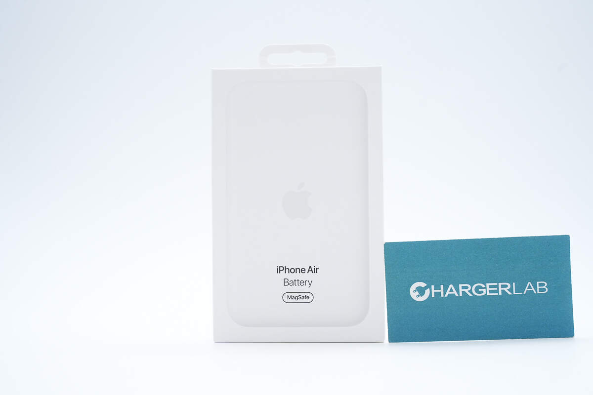
The front of the packaging box features an image of the product along with its name.
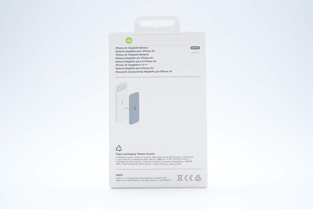
The back of the packaging displays the product name in multiple languages, usage illustrations, CE certification information, and other details.
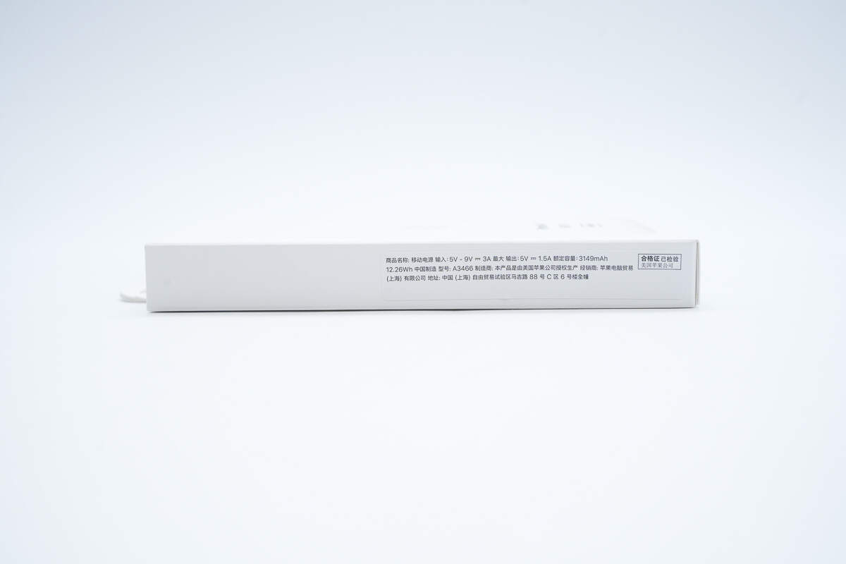
The side of the packaging box has a label with the product specifications.
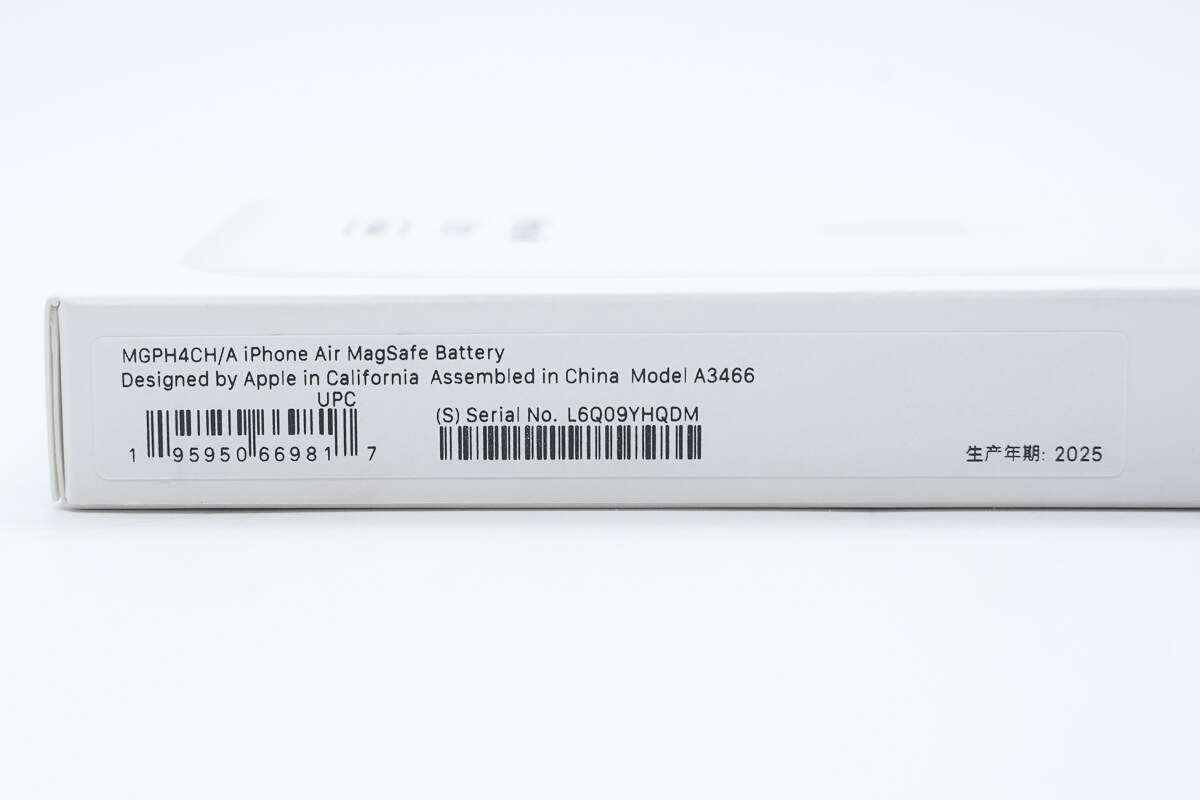
The other side of the packaging box features a sticker showing the production date, serial number, and “Made in China.”
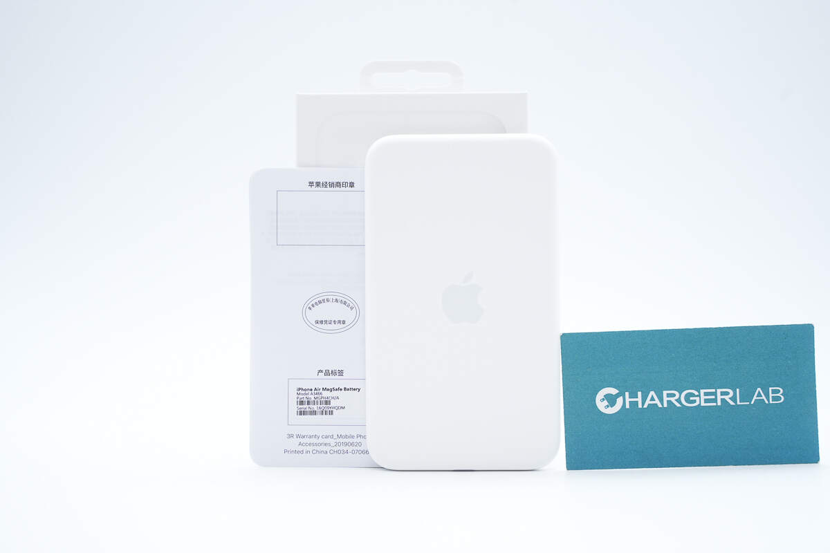
The package includes the MagSafe Battery, a user manual, and a warranty card.
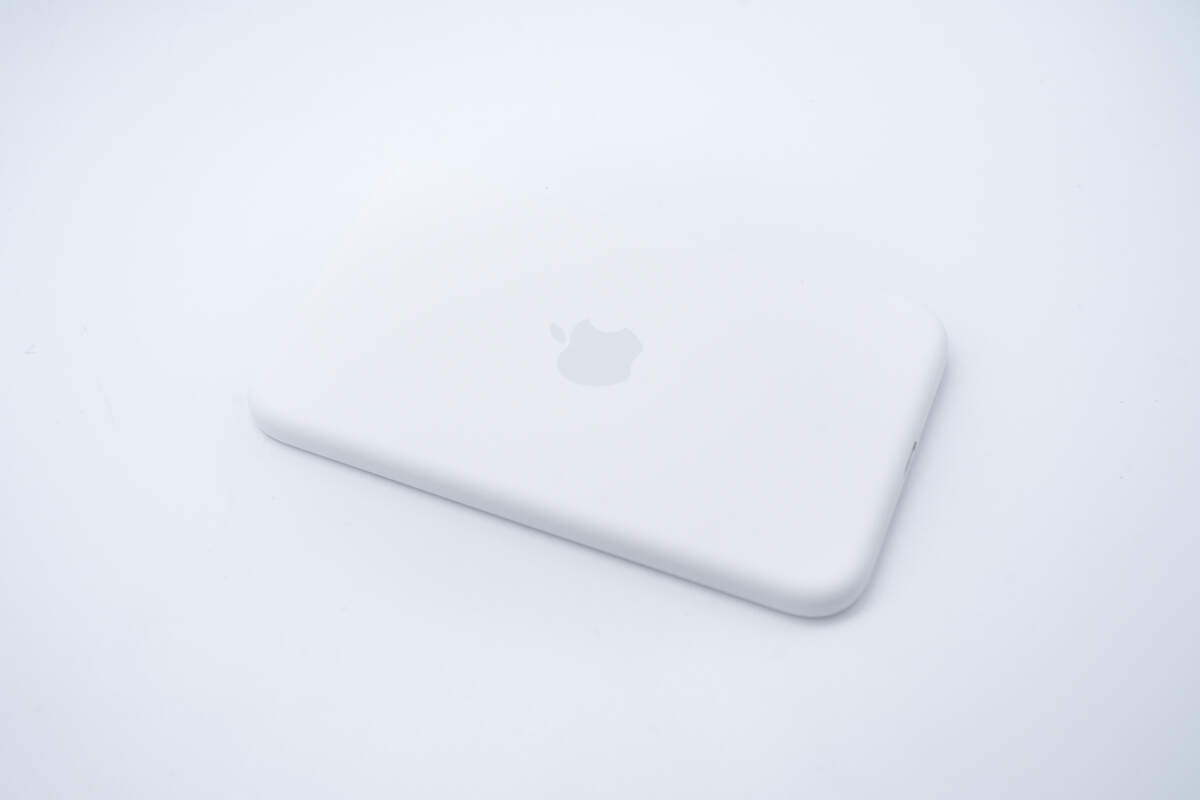
It is wrapped in paper to prevent scratches and wear.
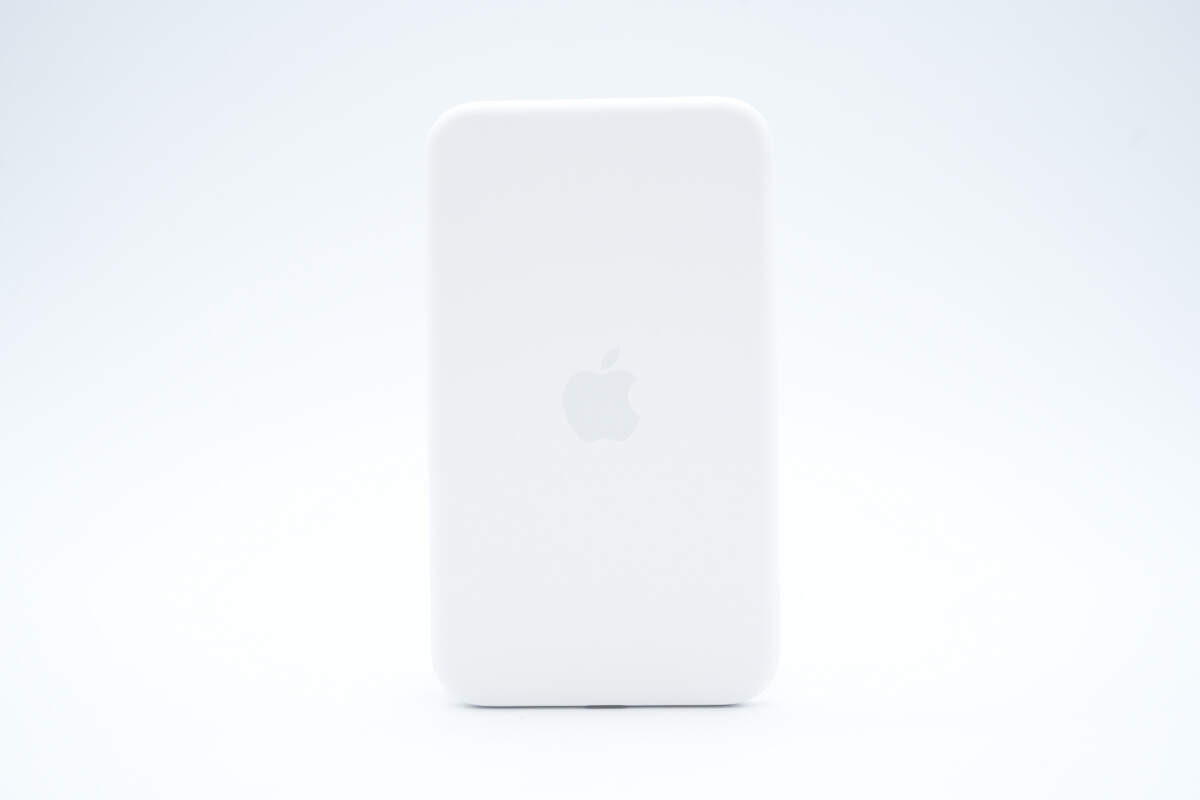
The back features the Apple logo.
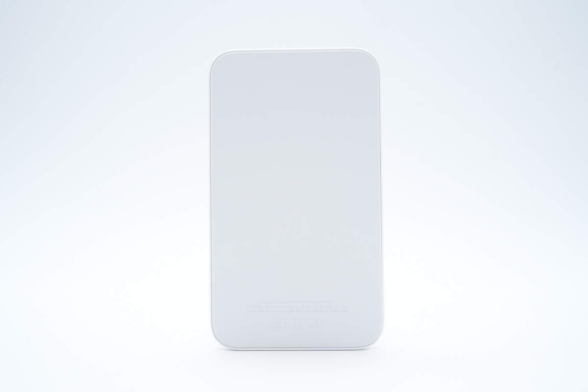
The side that attaches to the phone uses a skin-like material.
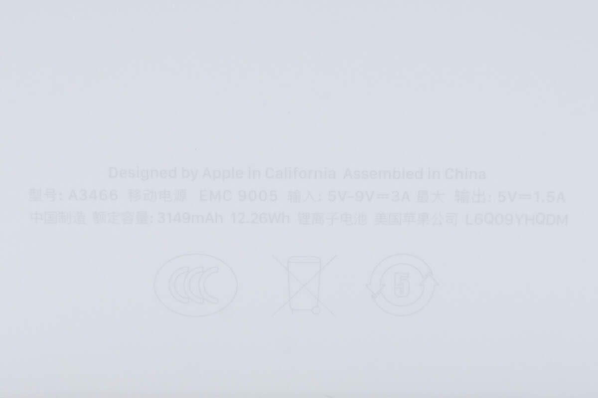
Model: A3466
Input: 5-9V 3A
Output: 5V 1.5A
Rated Capacity: 3149mAh, 12.26Wh
Battery Type: Lithium-ion battery
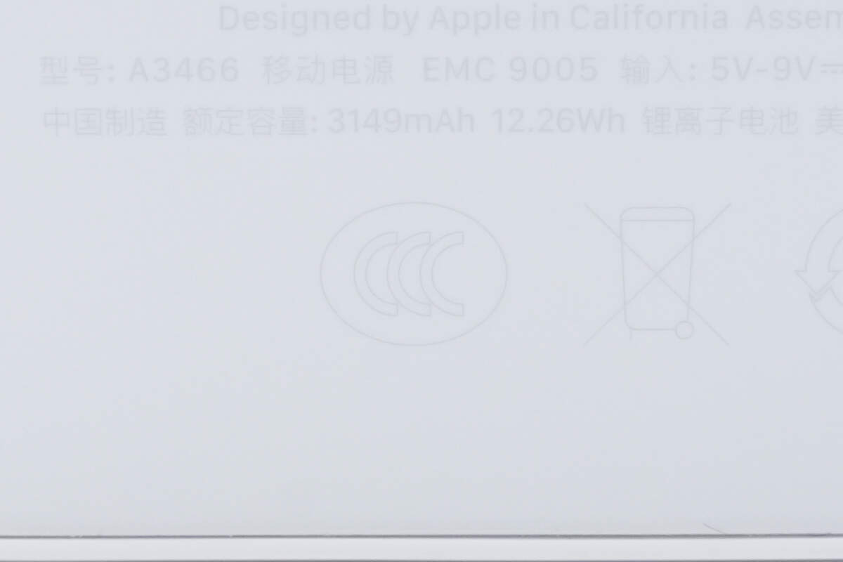
It has passed the CCC certification.
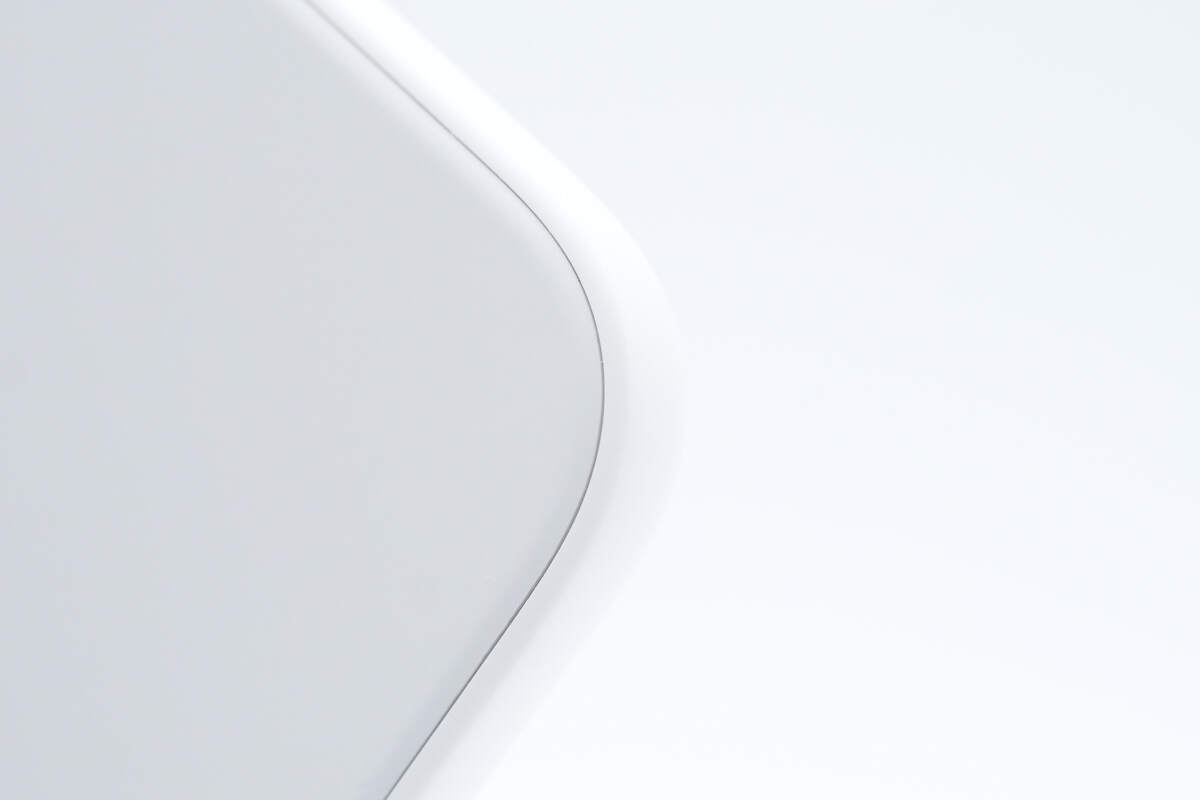
Close-up of the seam.
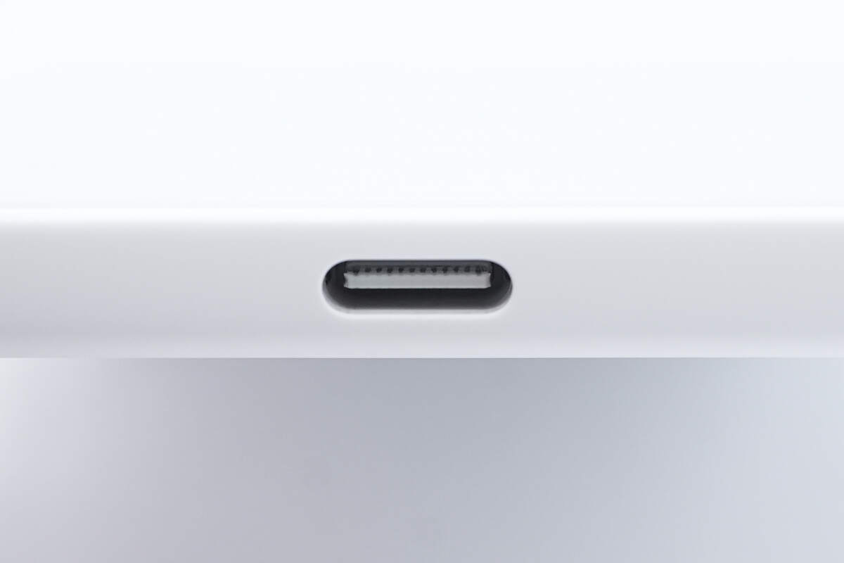
There is a USB-C port located at the bottom.
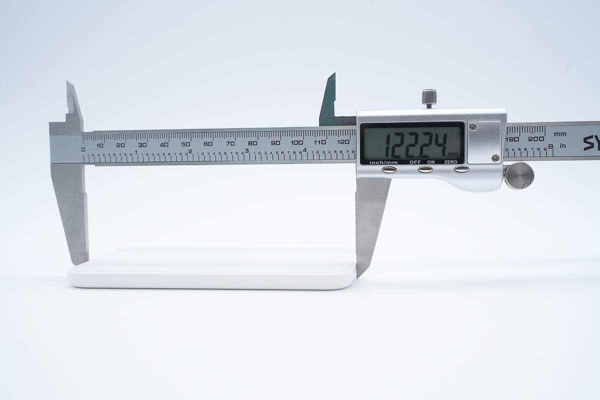
The length is about 122.2 mm (4.81 inches).
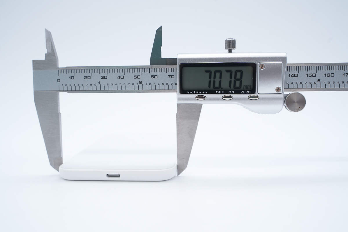
The width is about 70.8 mm (2.79 inches).
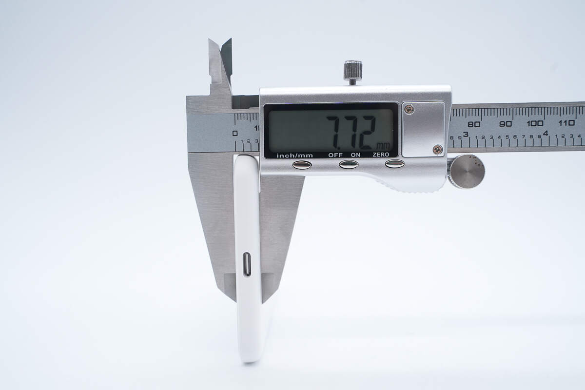
The thickness is about 7.7 mm (0.3 inches).
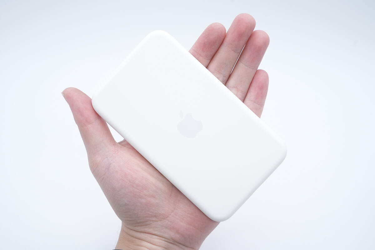
That's how big it is in the hand.
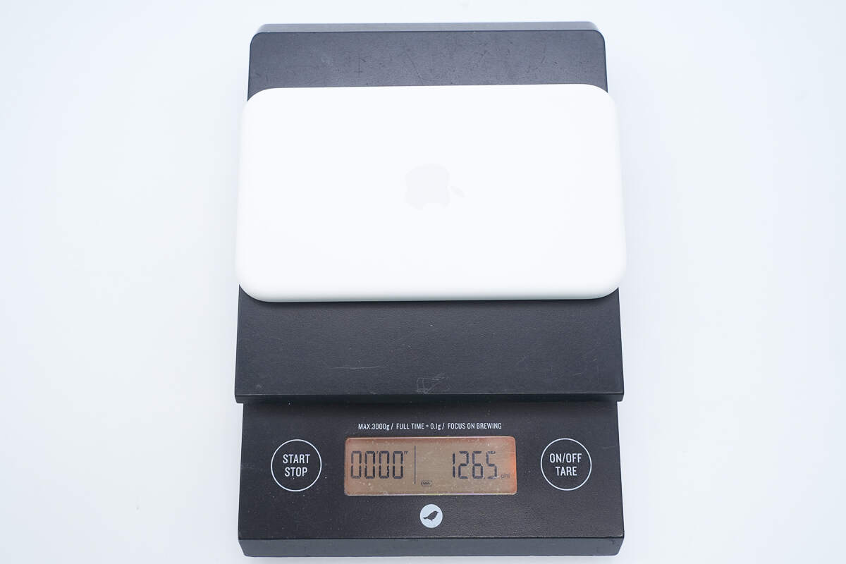
The weight is about 126.5 g (4.46 oz).
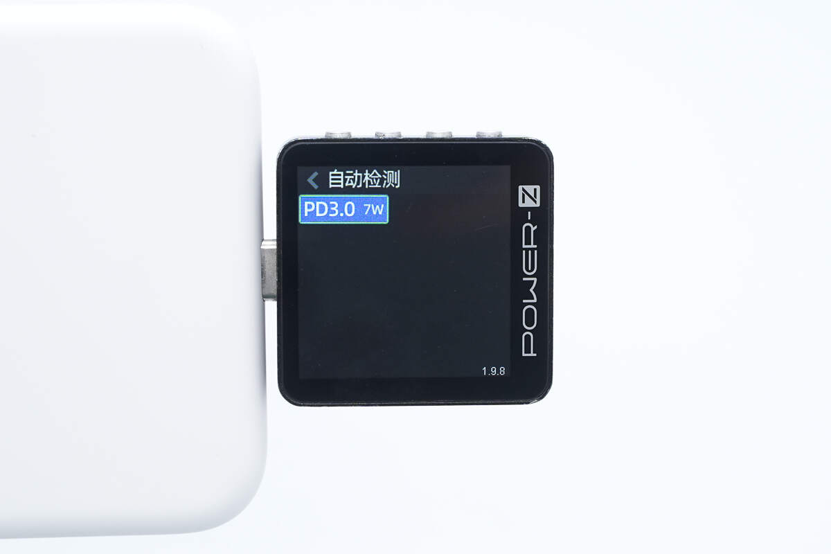
ChargerLAB POWER-Z KM003C shows that it supports PD3.0.
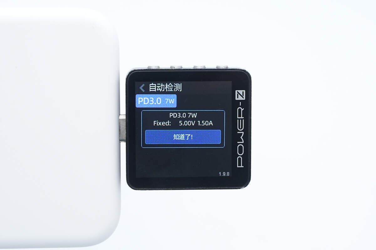
And it has one fixed PDO, which is 5V1.5A.
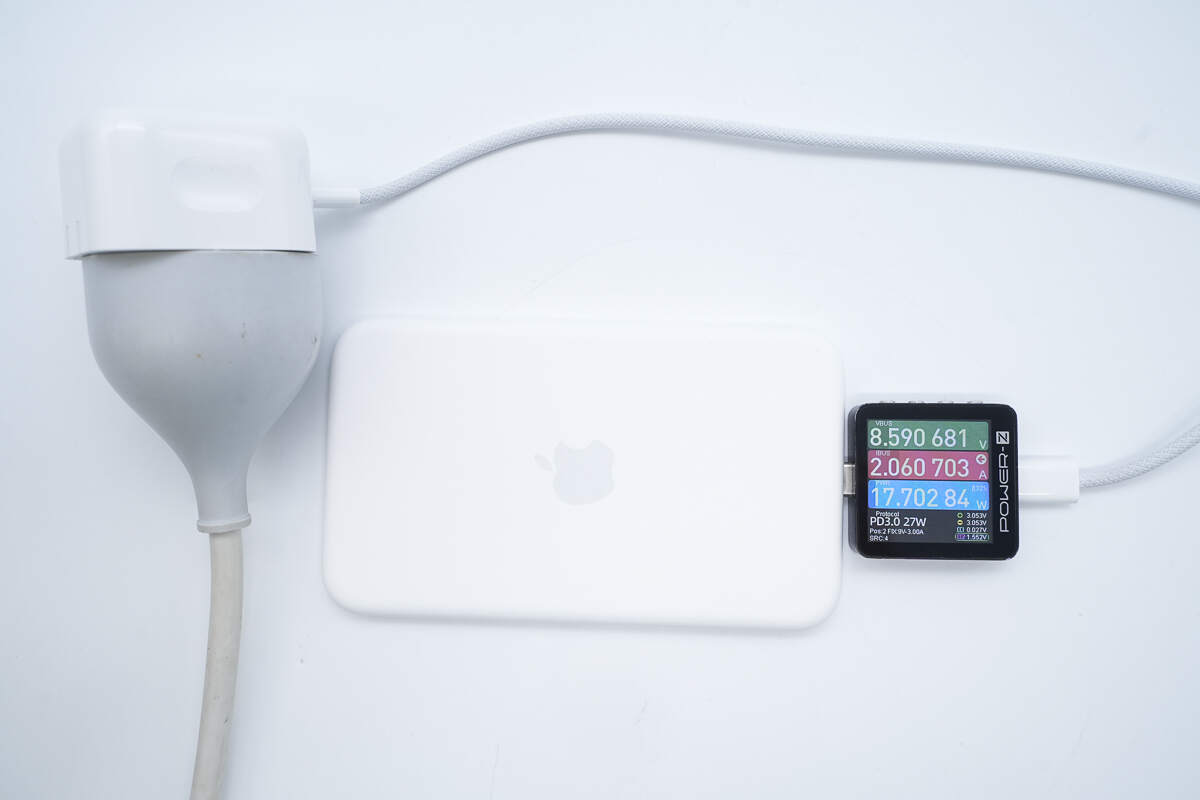
Charging the MagSafe Battery with the Apple 40W charger, the voltage is 8.6V, the current is 2.06A, and the power is 17.7W.
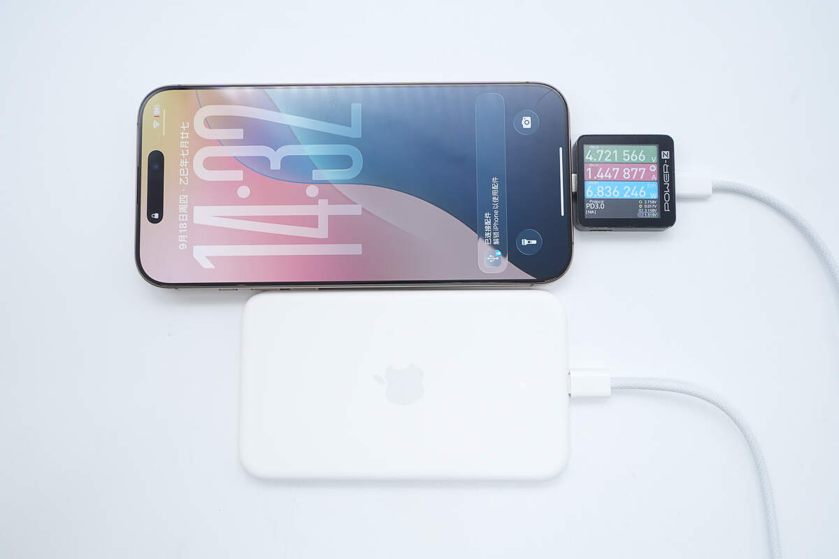
When the MagSafe Battery is connected to the iPhone 16 Pro Max for charging, the voltage is about 4.72V, the current is about 1.45A, and the power is about 6.84W.
There is an LED indicator on the back.
Teardown
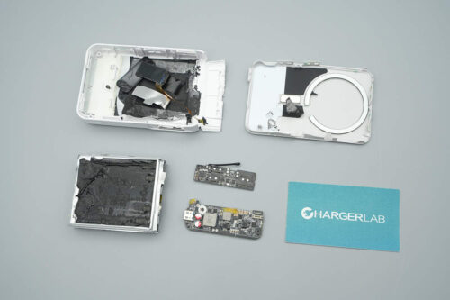
Next, let's take it apart to see its internal components and structure.
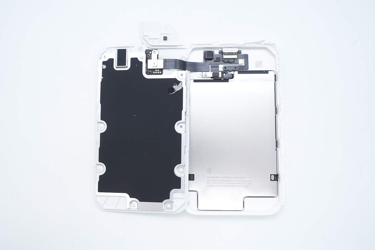
First, disassemble the casing along the seam, and the interior is a double-layer design.
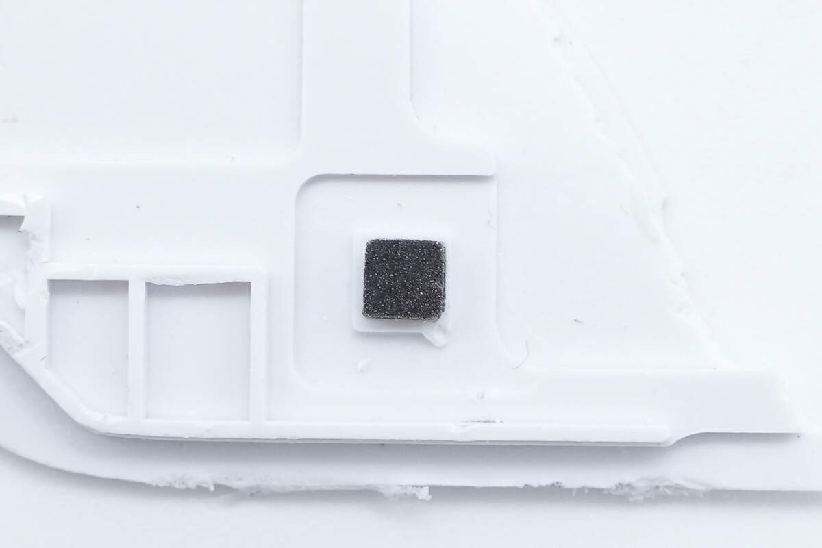
A cushioning foam pad is attached at the position corresponding to the filter inductor.
Inside the panel, the wireless charging module is connected to the battery casing via a flex cable.

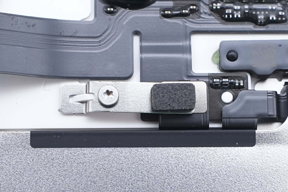
The flex cable connector is secured with a screw clamp.
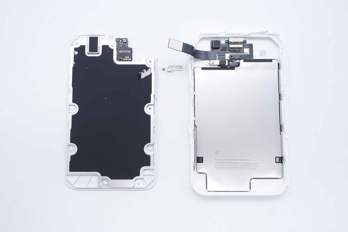
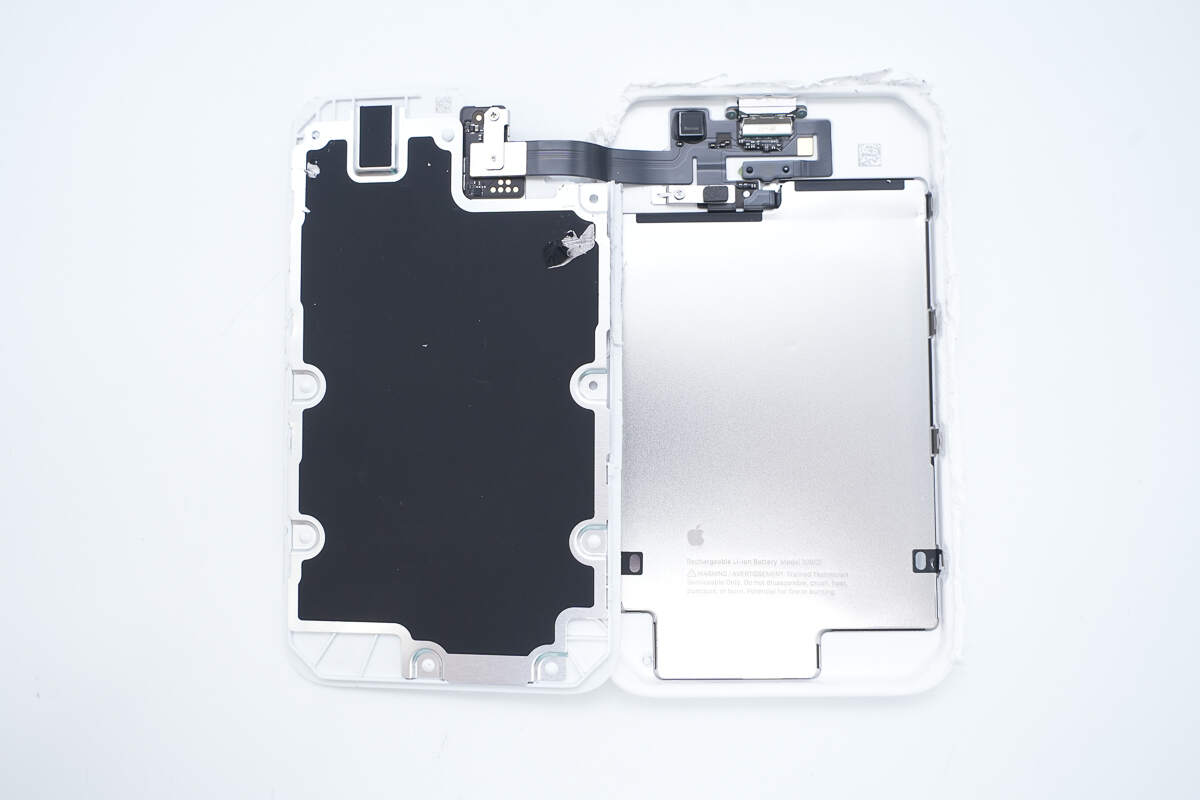
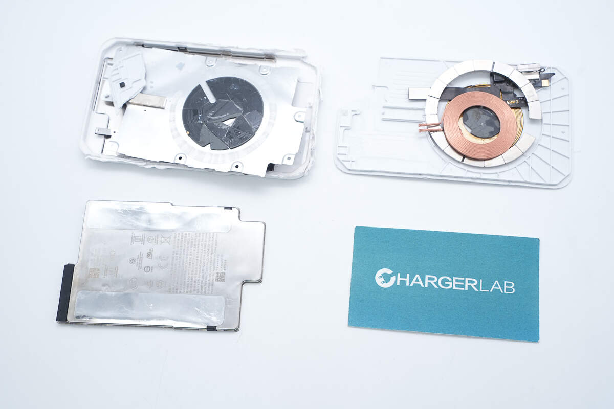
Disconnect the flex cable to separate the wireless charging module inside the panel from the battery component within the casing.
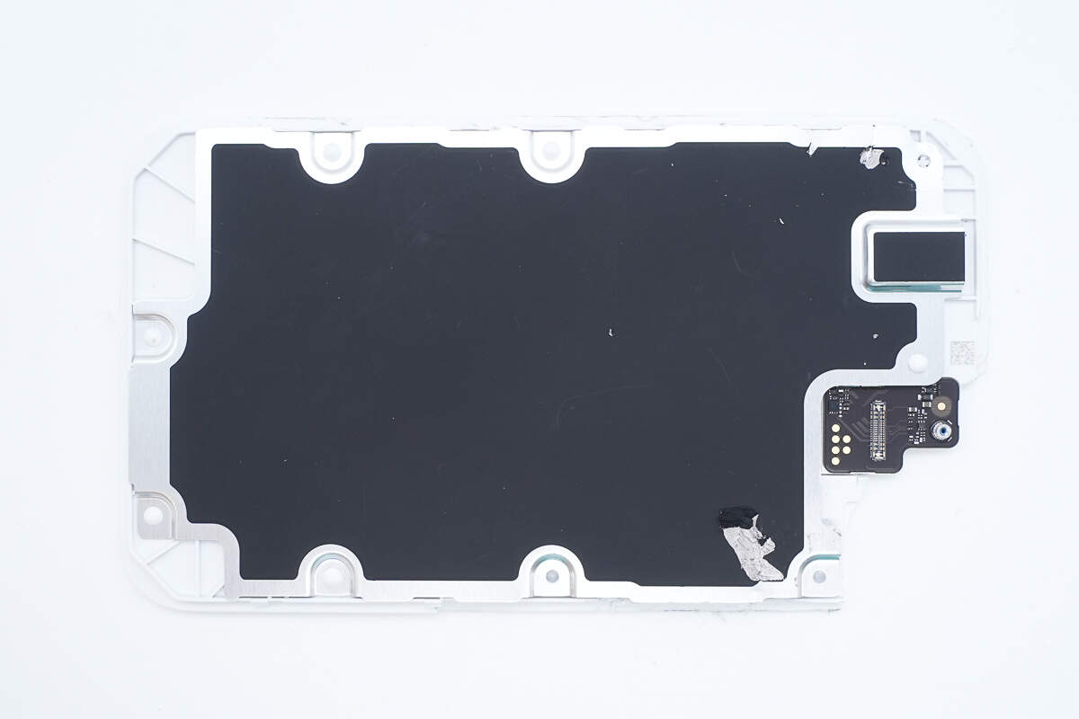
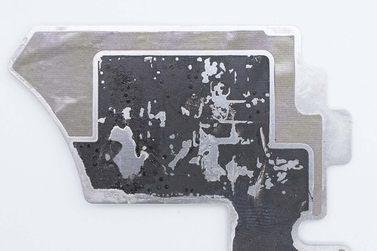
The back of the wireless charging module is covered with an aluminum alloy plate.
The aluminum alloy plate is secured with plastic heat welding.
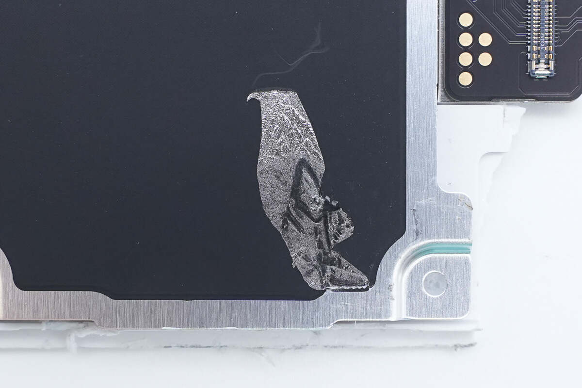
A graphite thermal pad is attached to the aluminum alloy plate.
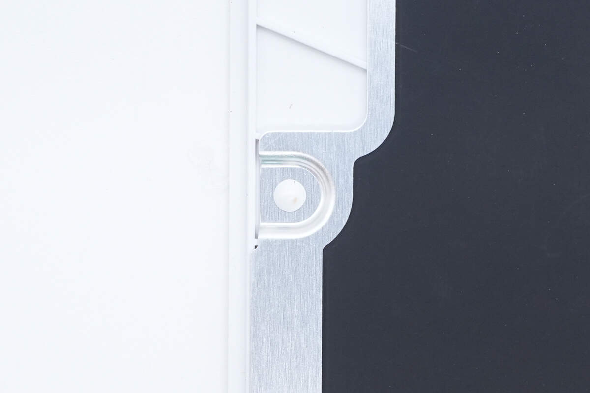
The aluminum alloy plate is stamped with a raised bump corresponding to the shapes of the components beneath.

After removing the aluminum alloy plate, a magnetic shielding sheet and a positioning magnet are found attached inside the plate.
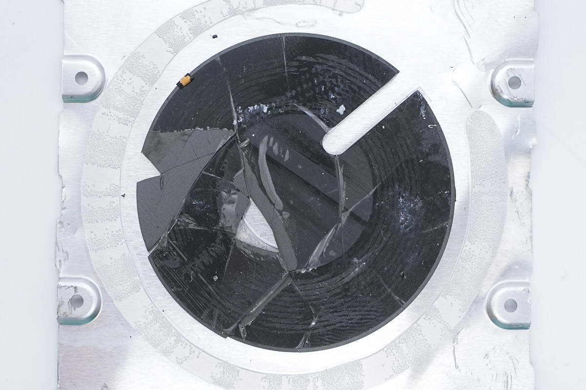
The magnetic shielding sheet is slotted to allow the coil wiring to pass through, reducing the overall thickness.
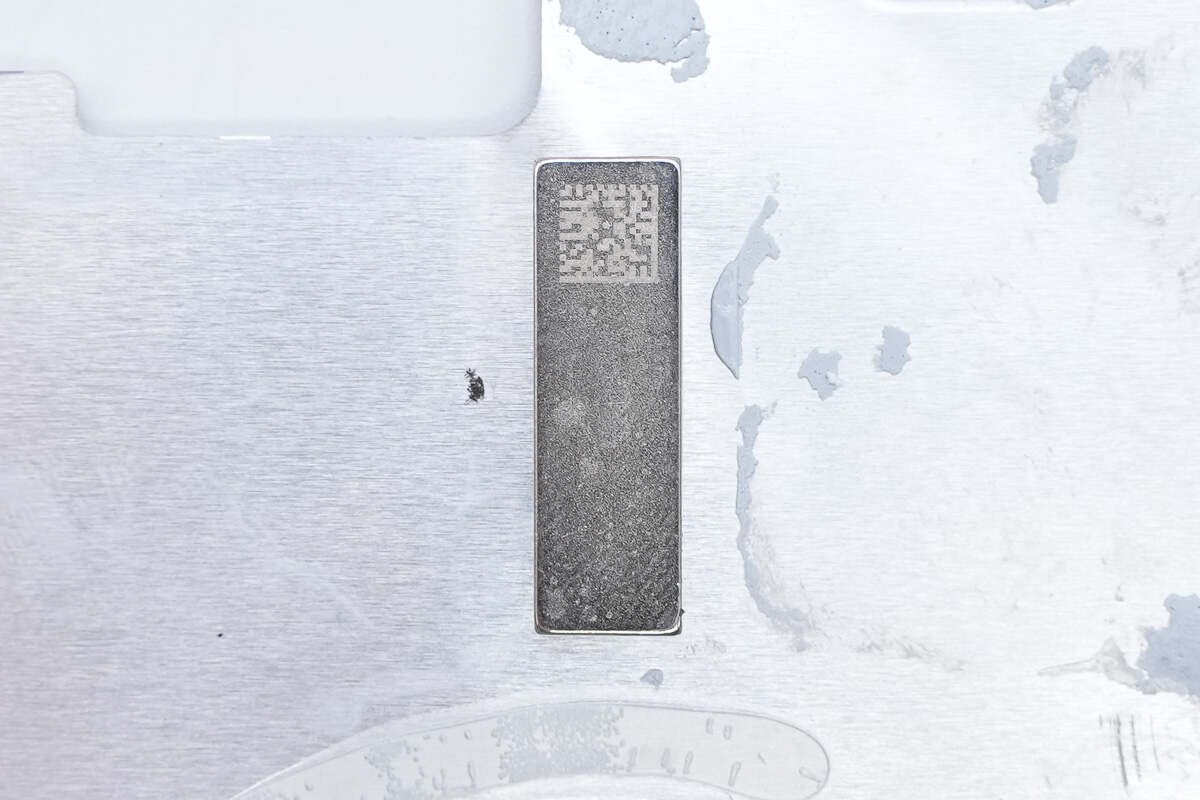
A QR code is printed on the positioning magnet.
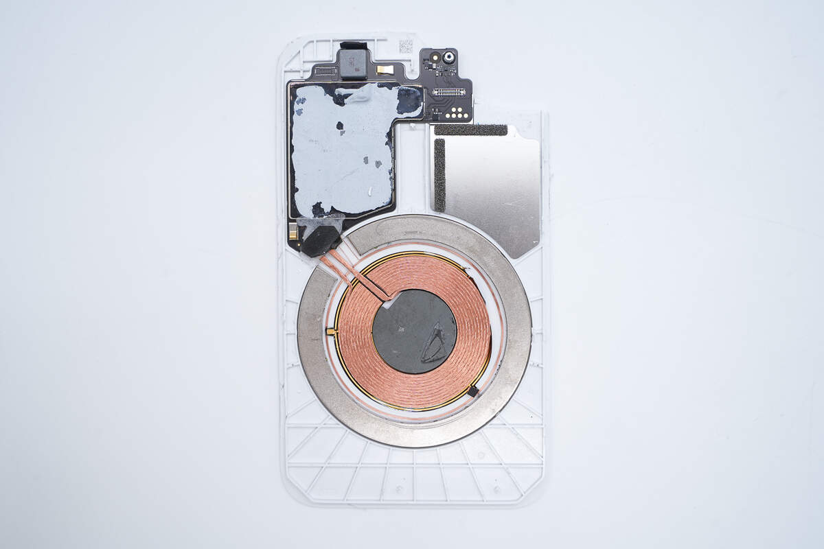
Inside the panel, there is a PCBA module and a wireless charging coil.
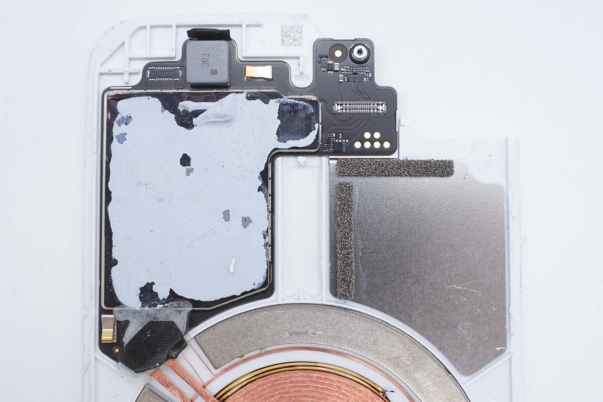
The PCBA module is equipped with a metal shielding cover and coated with thermal adhesive to facilitate heat dissipation through contact with the aluminum alloy plate.
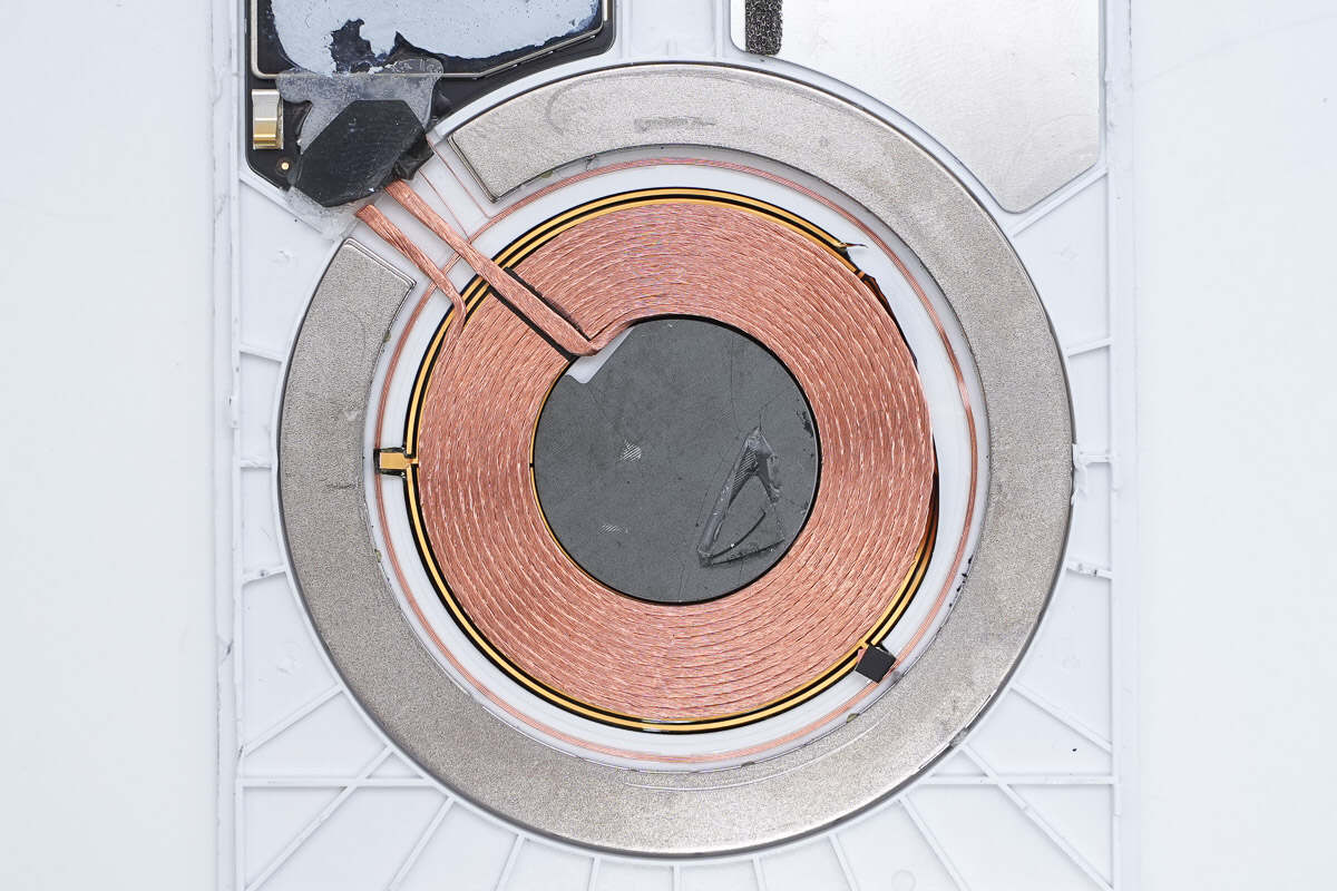
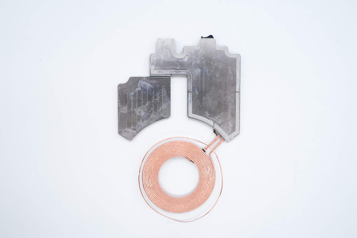
The magnet is arranged around the edge of the wireless charging coil to attach to the phone.
A communication coil is also placed between the wireless charging coil and the magnet.
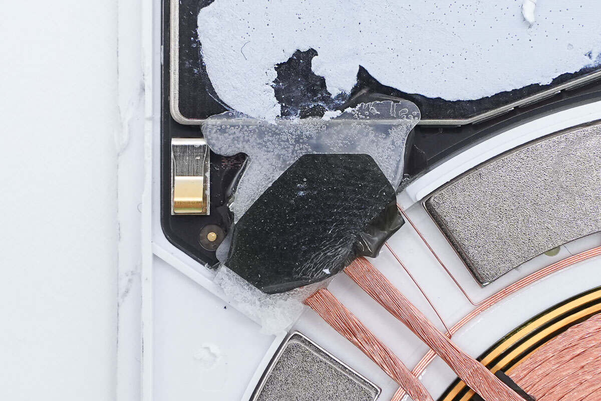
The solder joints of the wireless charging coil are reinforced with adhesive and insulated with tape.
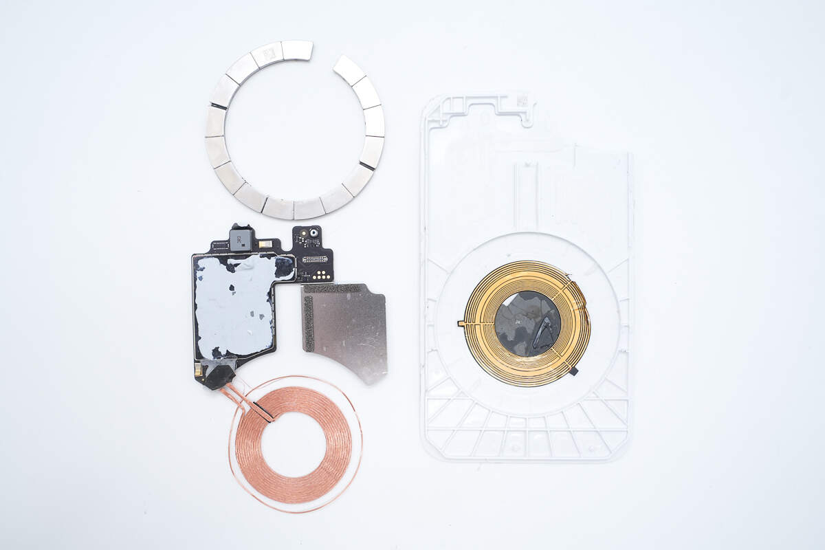
Remove the PCBA module, magnets, and wireless charging coil from inside the aluminum alloy plate.
Close-up of the shielding layer.
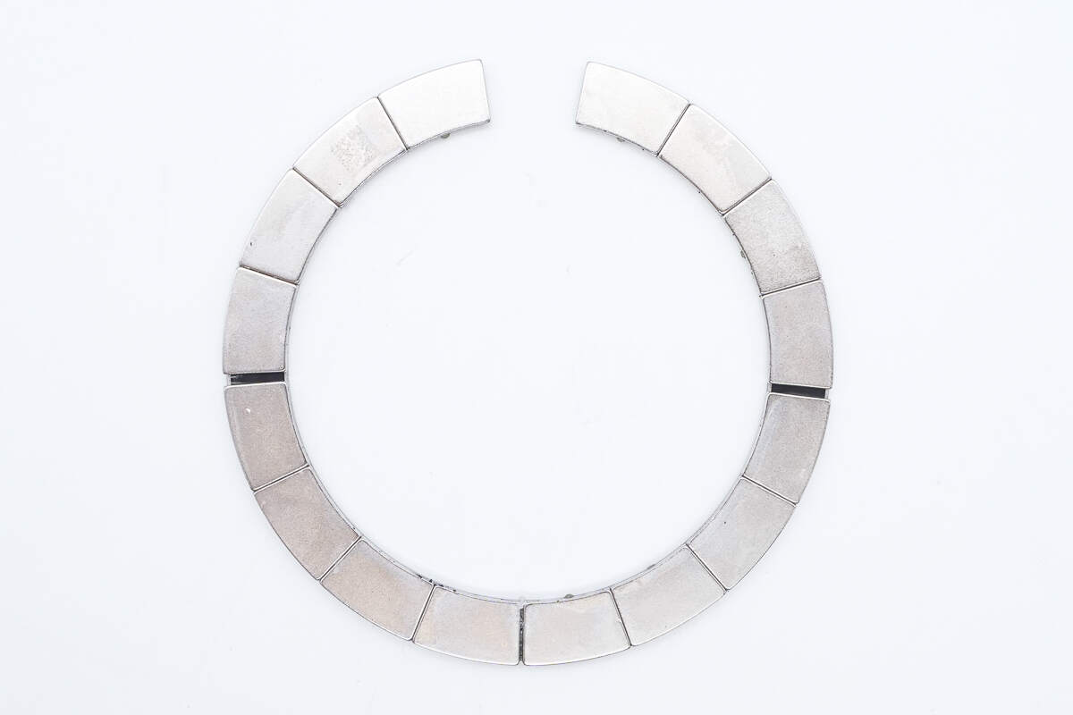
The ring-shaped magnet consists of a total of 16 individual magnets.
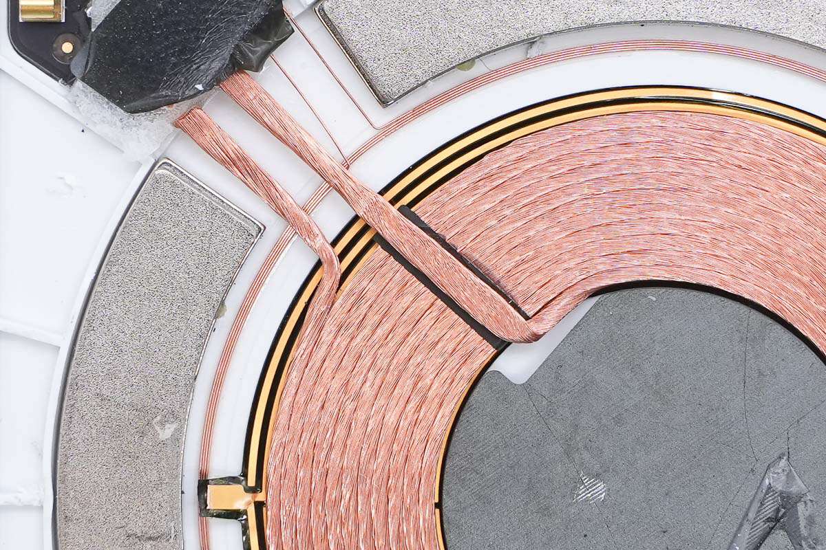
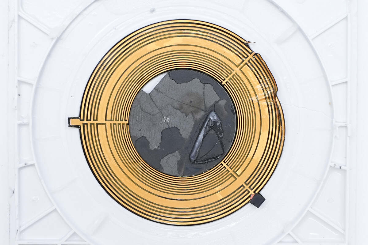
Close-up of the wireless charging coil and communication coil.
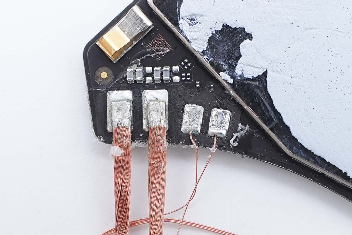
The coils are connected by soldering.
The back of the PCBA module is equipped with aluminum plates for heat dissipation.
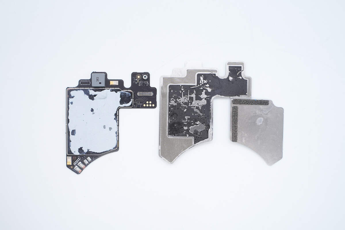
Separate the PCBA module and the aluminum plates.
The aluminum plate is lined with conductive fabric and uses double-sided adhesive to secure the PCBA module.
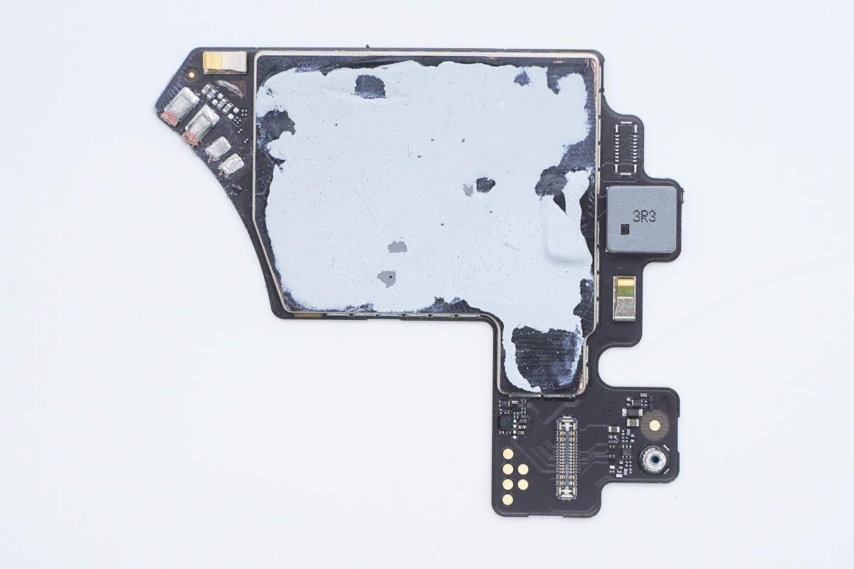
The front of the PCBA module is covered with a metal shielding case.
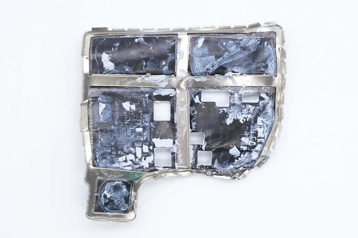
The shielding case is made up of a metal frame with adhesive tape applied.
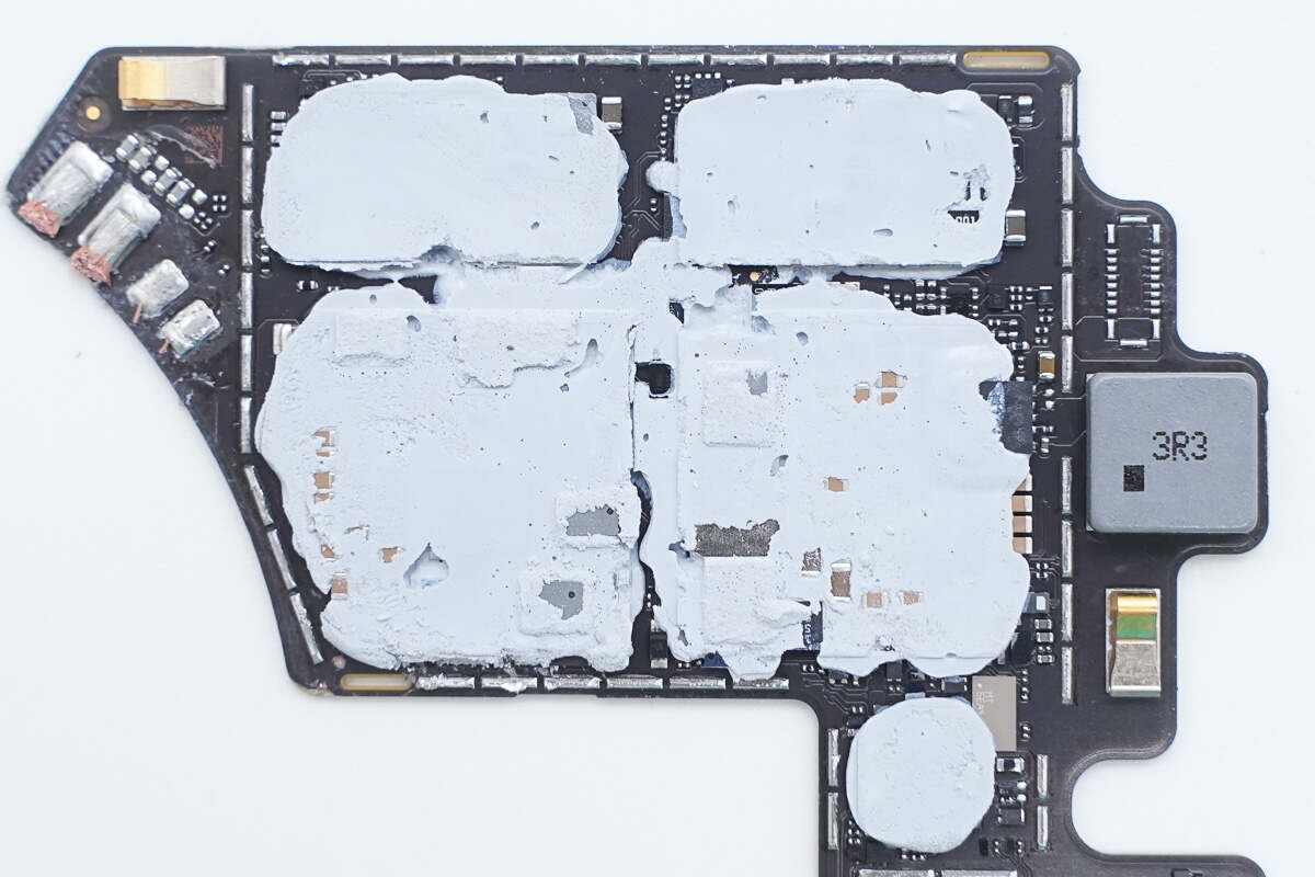
Thermal adhesive is applied to the components to enhance heat dissipation.
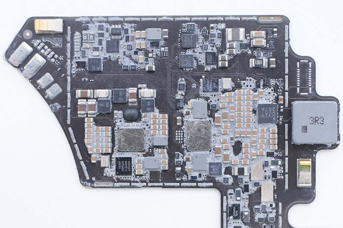
Clean off the thermal adhesive. Aluminum plates are attached to the wireless charging chip and power conversion chip to enhance heat dissipation.
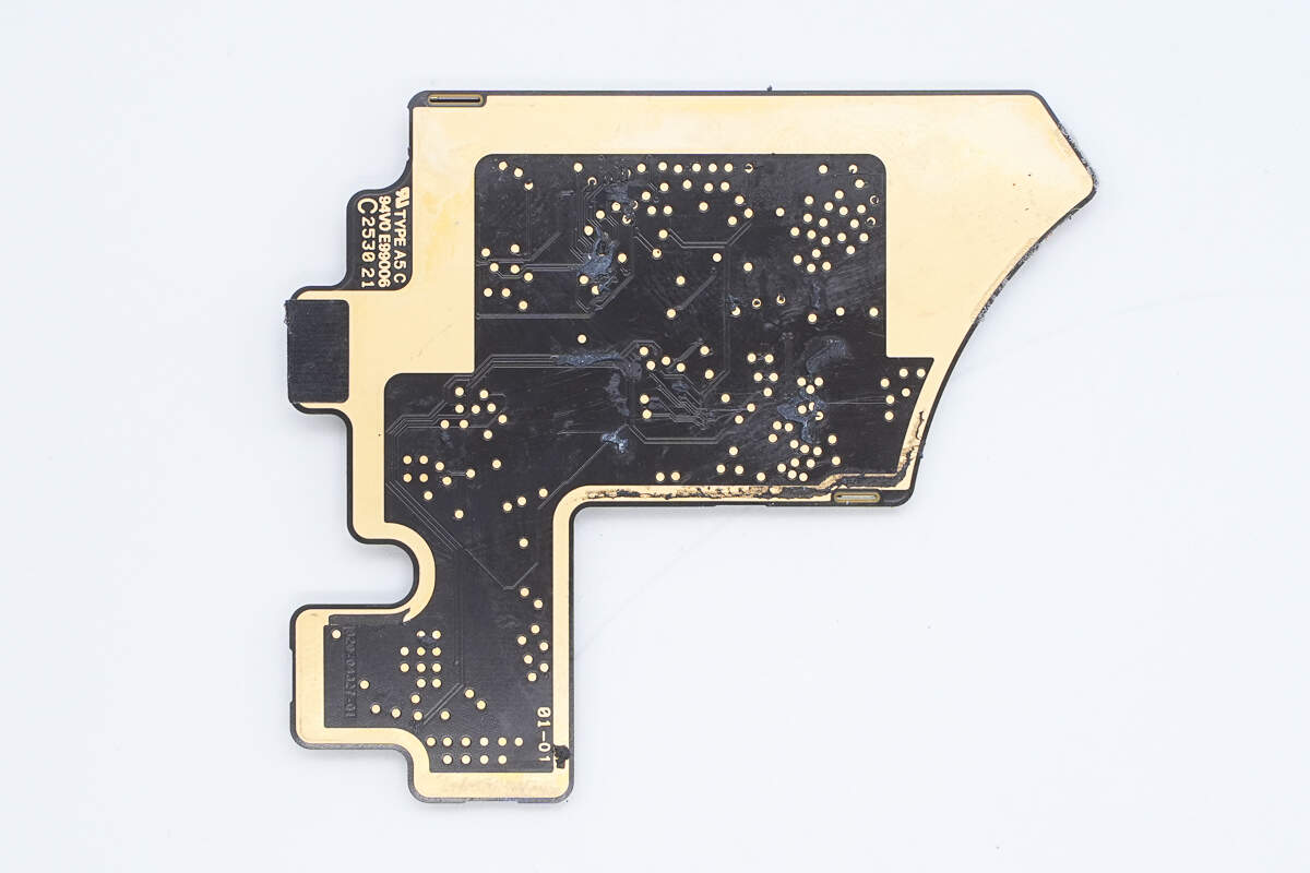
There are no components on the back of the PCBA module.
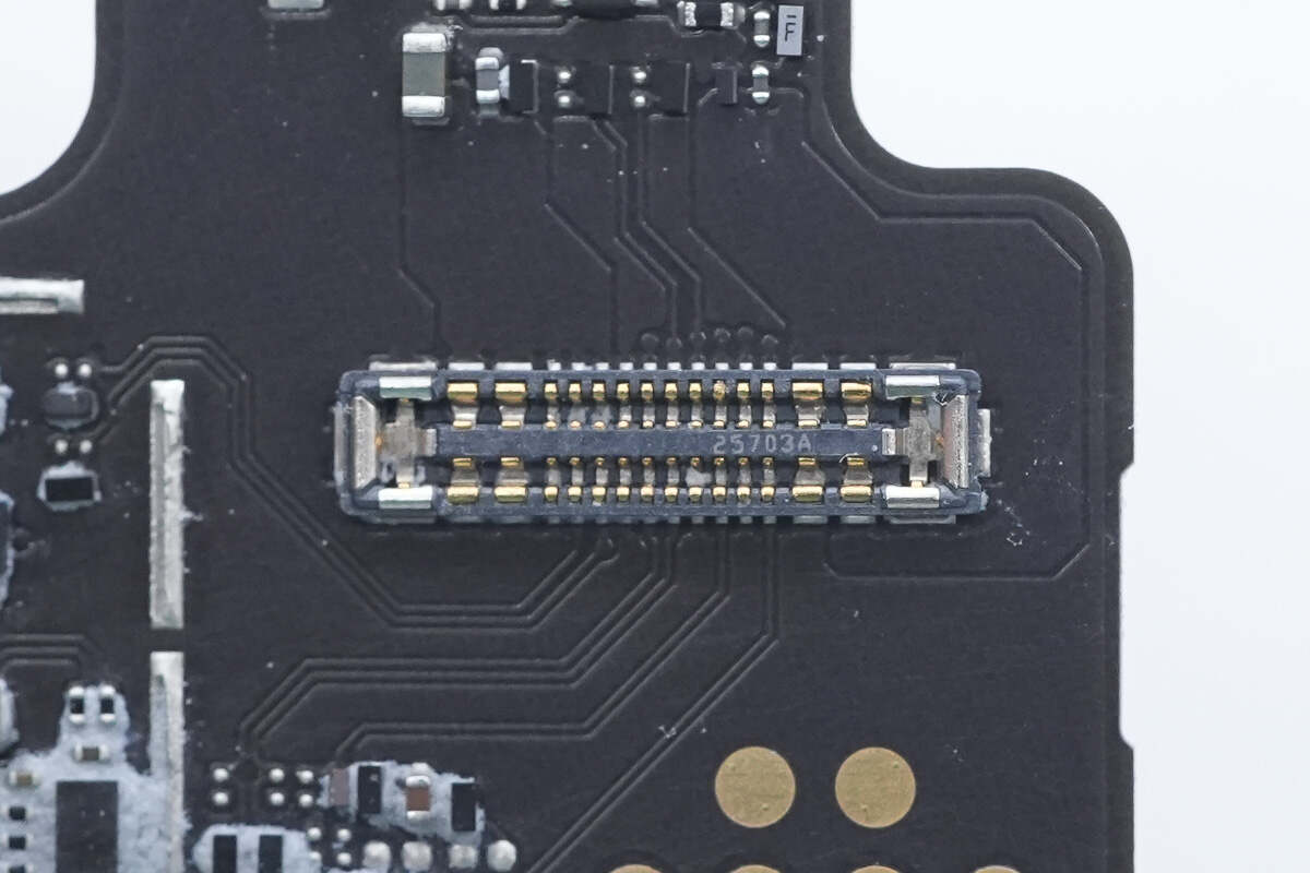
Close-up of the flex cable connector connected to the USB-C port and battery.
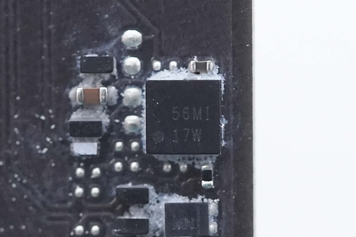
The protection chip for the USB-C port is from Texas Instruments, marked with "17W," model TPS2S300. It provides overvoltage and electrostatic discharge (ESD) protection by shorting the CC pin to VBUS, supports up to 24V withstand voltage, and supports a VCONN power supply. The chip comes in a WCSP package.
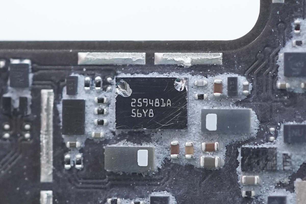
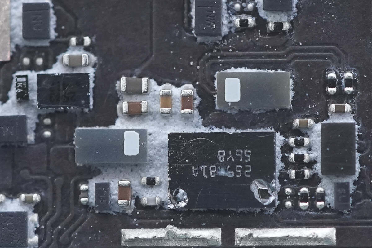
The electronic fuse is from Texas Instruments, model TPS259481A. It is a bidirectional electronic fuse that supports an operating voltage range of 3.5–23V, has an on-resistance of 12.2mΩ, supports a continuous current of 8A, and comes in a PWCSP package.
Close-up of the two current-sensing resistors.
Two MOSFETs are used for circuit switching control.
Close-up of the current-sensing sampling resistor.
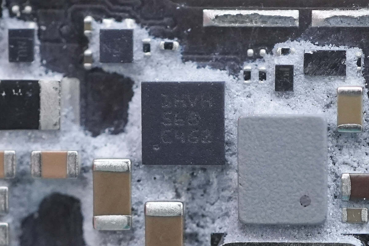
The surge protection chip is from Texas Instruments, marked with "1HVH," model TVS2200. It operates at 22V and provides overvoltage protection. The chip is packaged in a SON package.
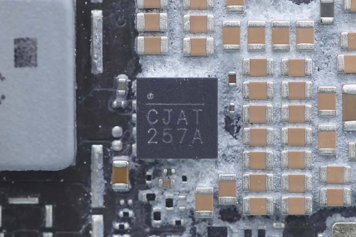
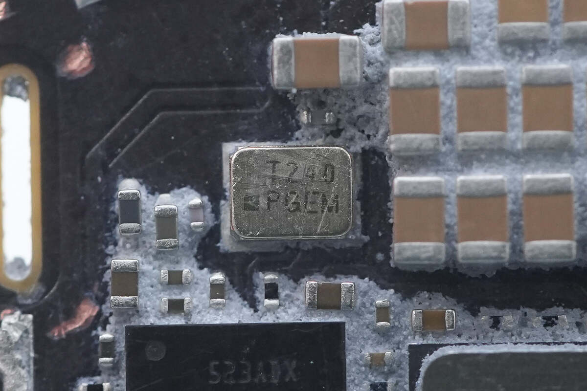
The power management chip is marked with "CJAT 257A."
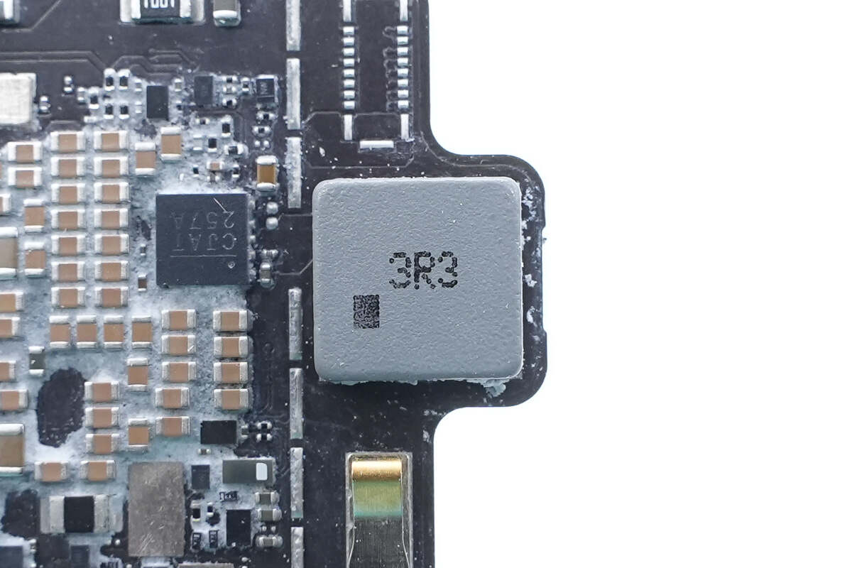
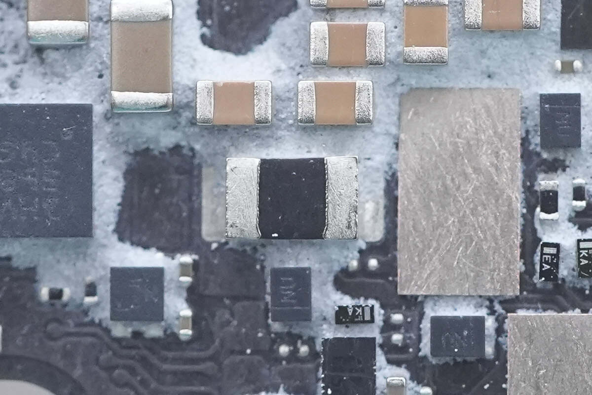
Close-up of the 3.3μH alloy inductor.
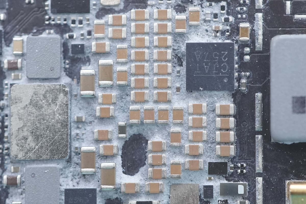
The MLCC capacitors are used for power supply filtering.
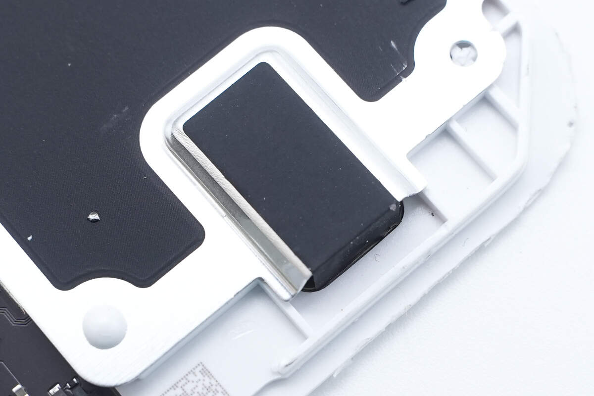
A metal spring contact is used to connect the aluminum alloy cover plate to ground.
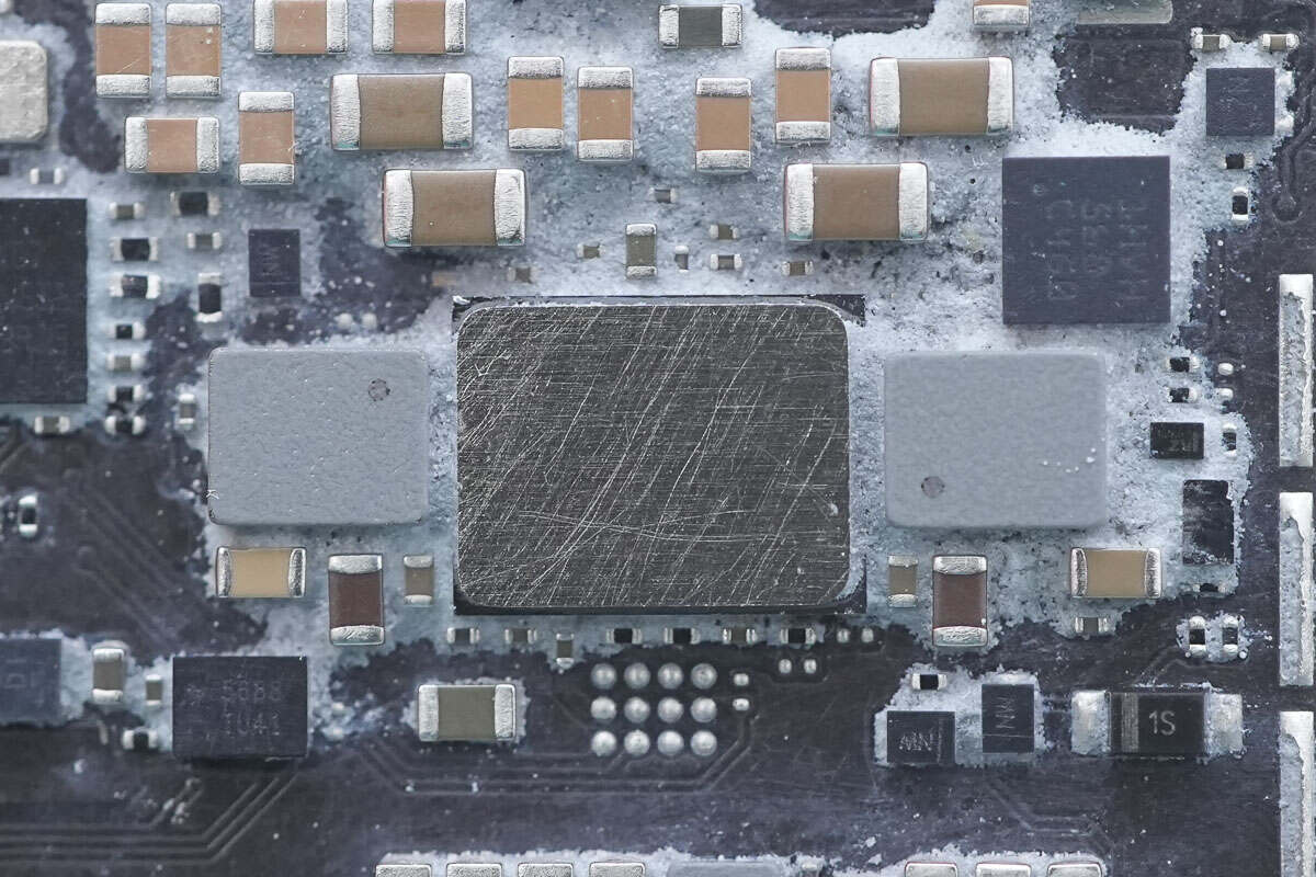
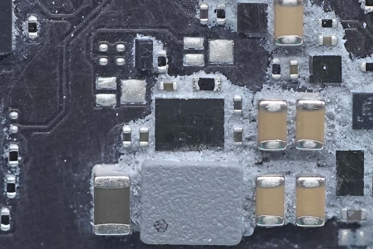
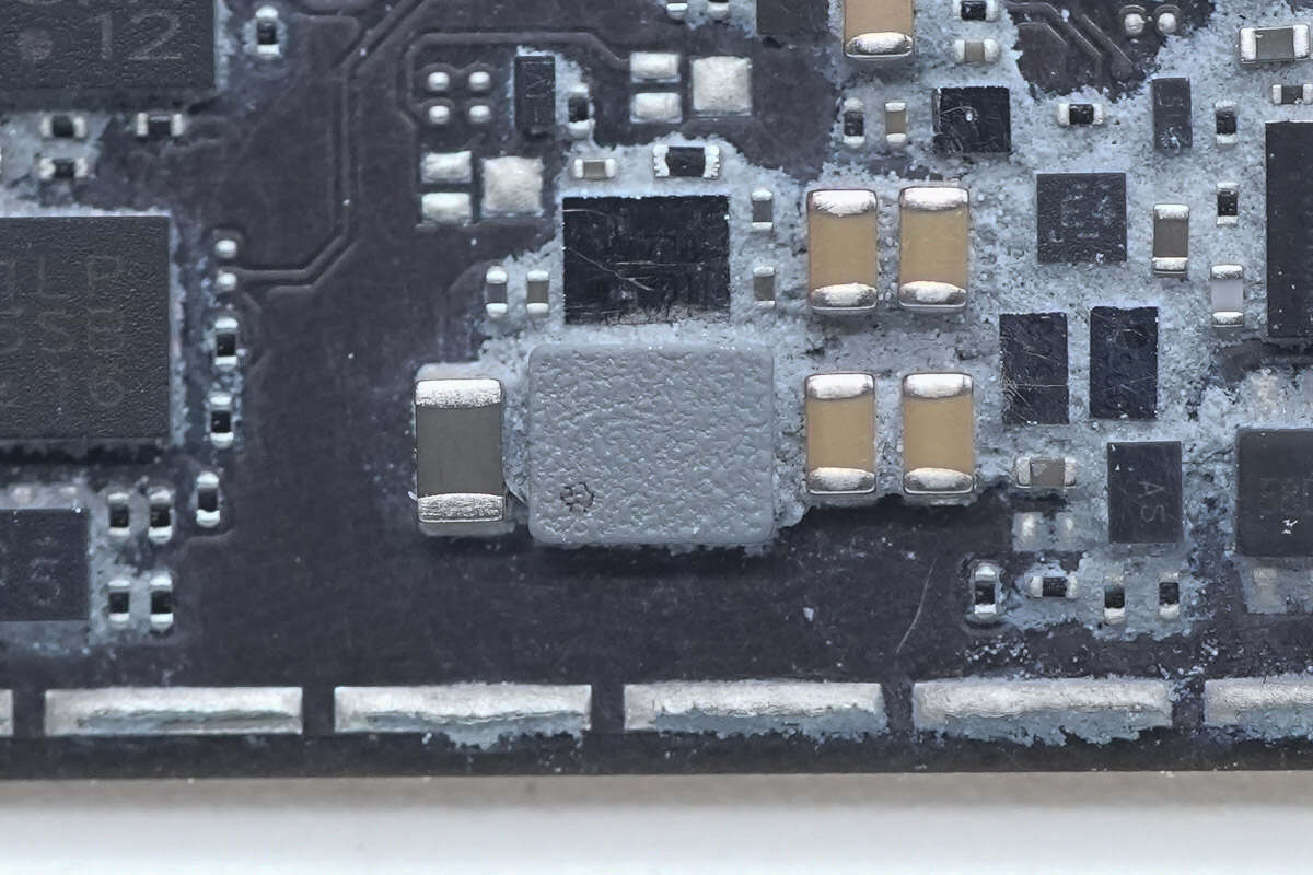
The power chip is attached to an aluminum plate with thermal adhesive to enhance heat dissipation.
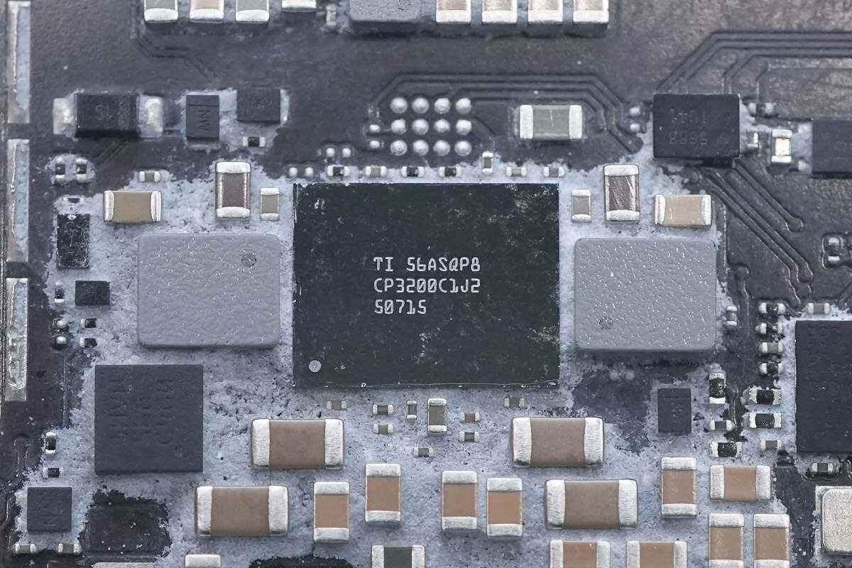
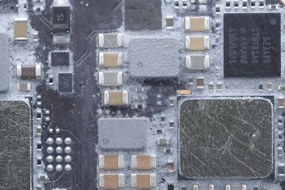
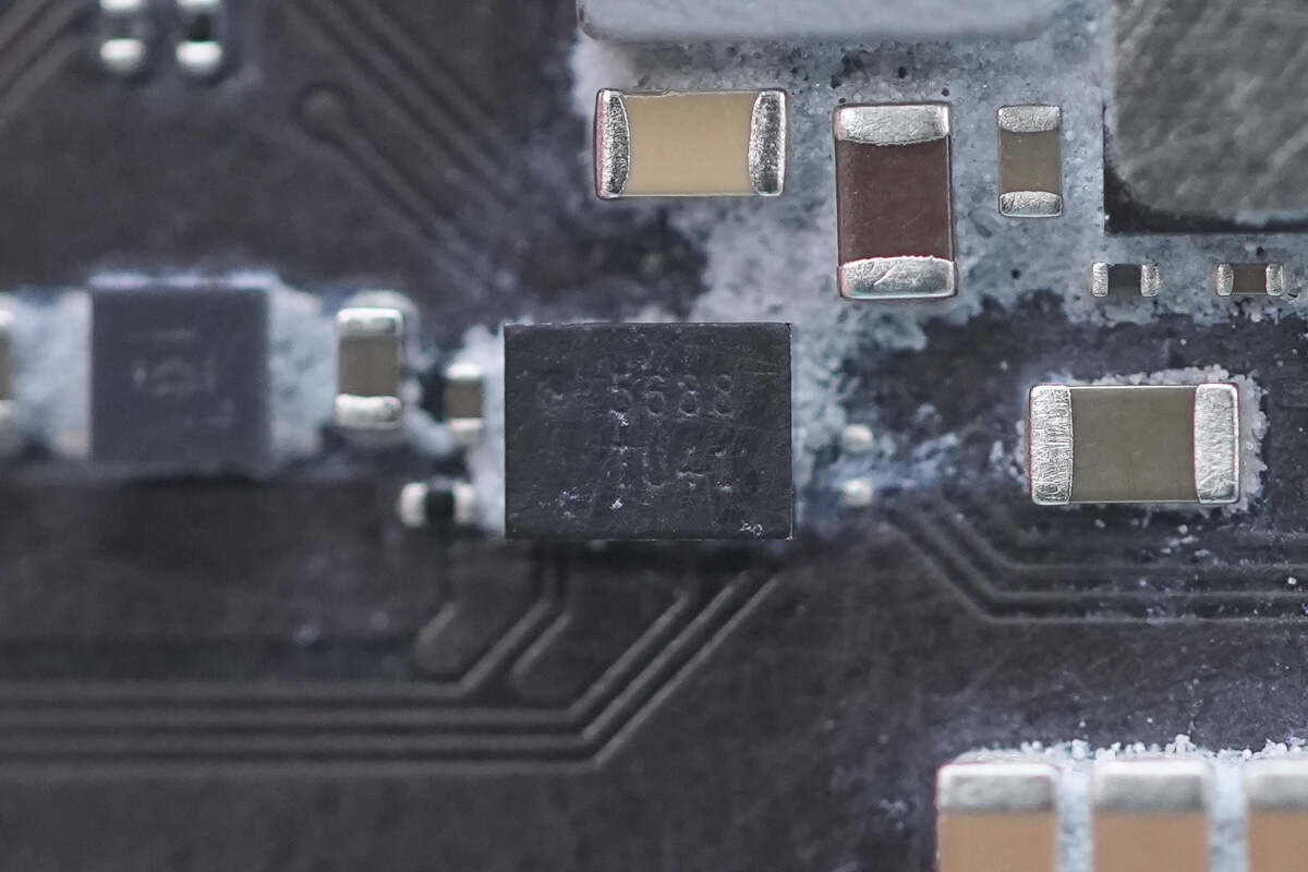
The power chip is from Texas Instruments, marked with CP3200C1J2, and is flanked by SMD inductors on both sides.
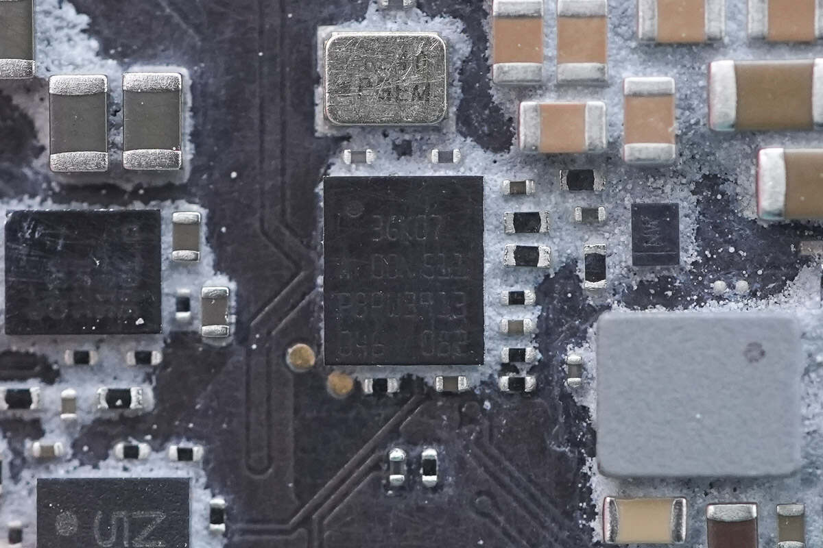
The PD controller is marked with "3GK07."
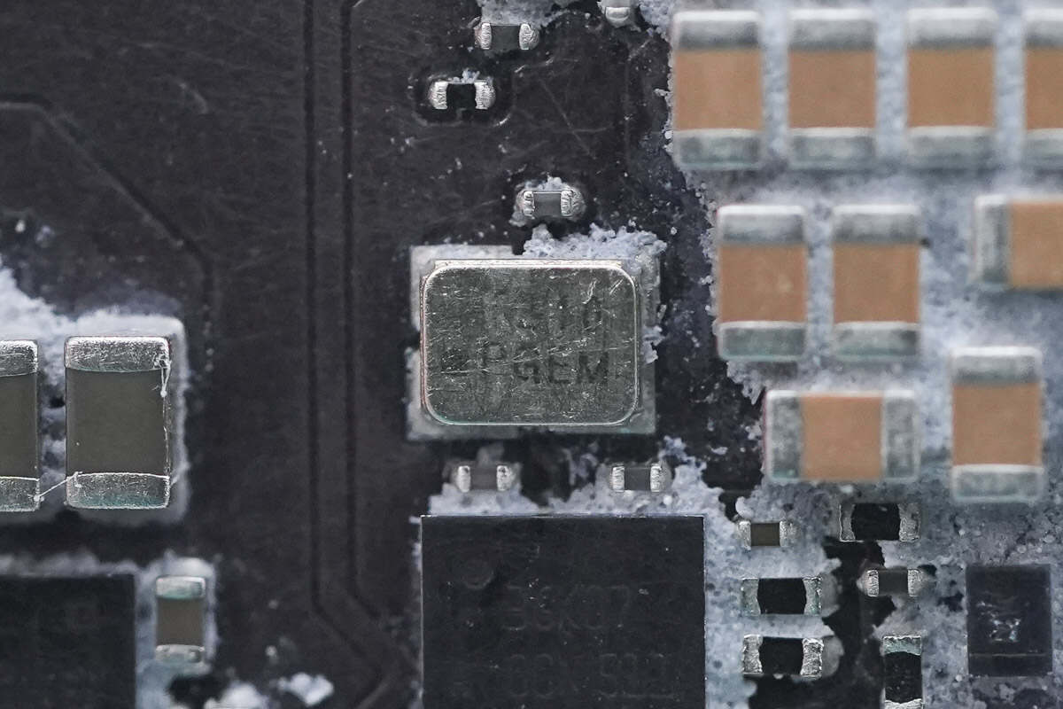
Close-up of the crystal oscillator.
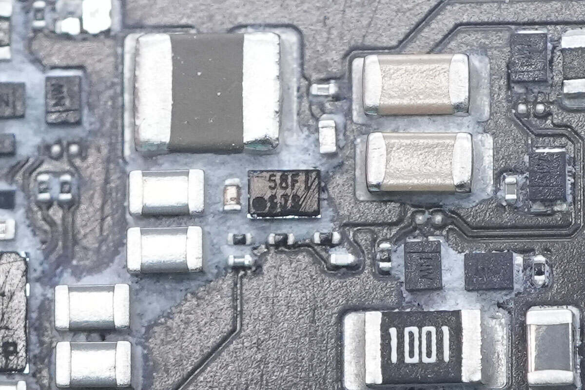
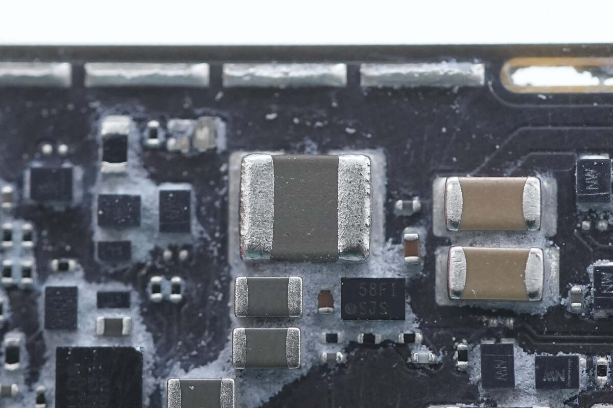
The boost converter chip is from Texas Instruments, marked with "SJS," model TPS61046. It is a synchronous boost converter with an integrated internal switch, supporting an input voltage range of 1.8–5.5V and an output voltage up to 28V. The chip features output short-circuit protection, overvoltage protection, and thermal shutdown protection. It comes in a WCSP package.
Close-up of the SMD boost inductor.
The USB-C port controller is from Infineon, model CYPD2122B. It features a built-in Cortex-M0 processor running at 48MHz, includes 32KB of FLASH memory, integrates a Type-C transceiver, and comes in a WLCSP package.
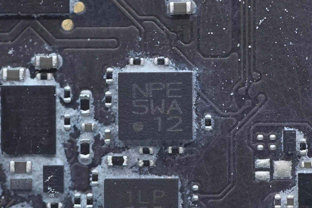
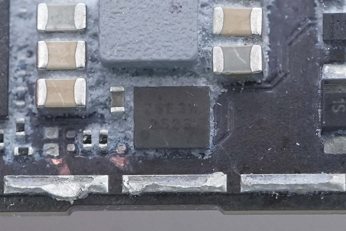
Close-up of the chip marked with "NPE 5WA 12."
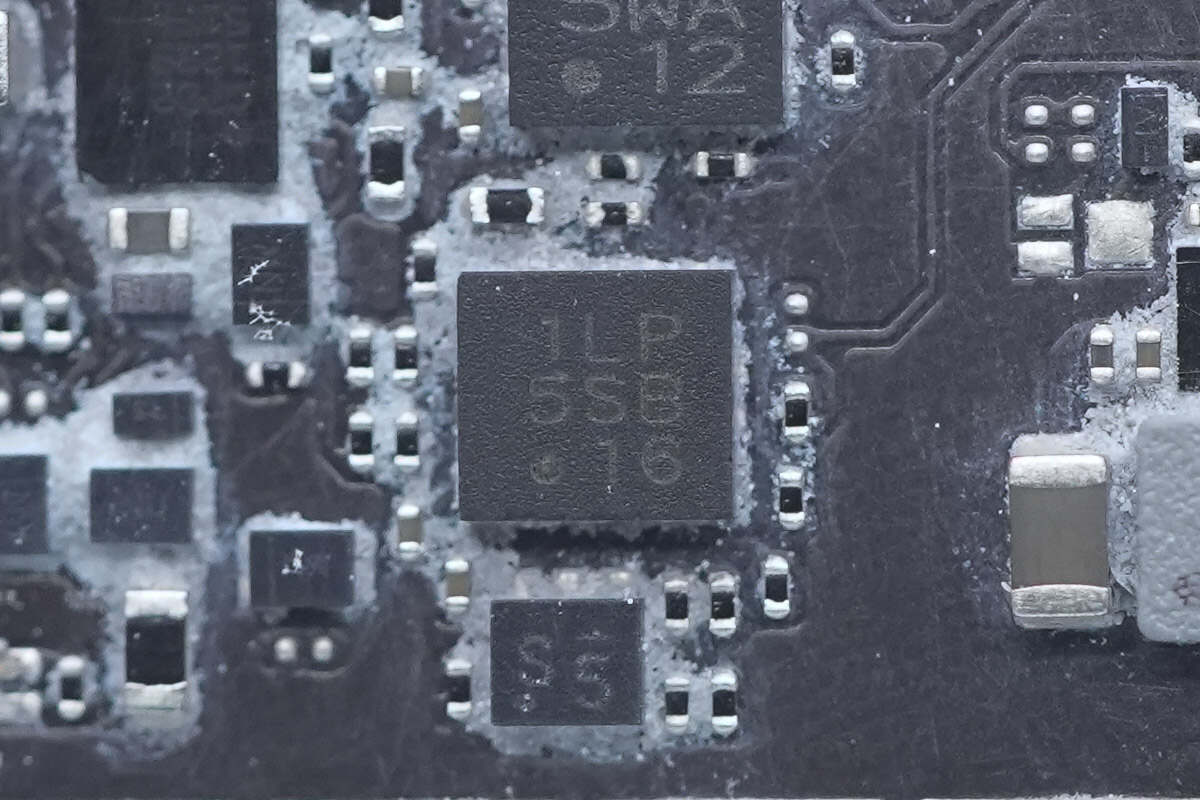
Close-up of the chip marked with "1LP 5SB 16."
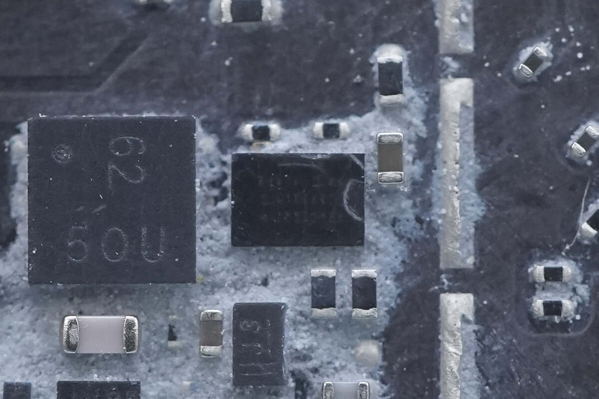
A power chip marked with "4728."
Close-up of the accompanying SMD inductor.
This chip has no markings and cannot be identified.
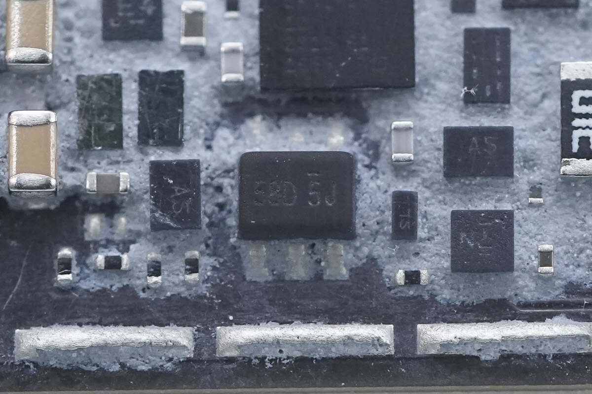
Close-up of the chip marked with "58D 5J."
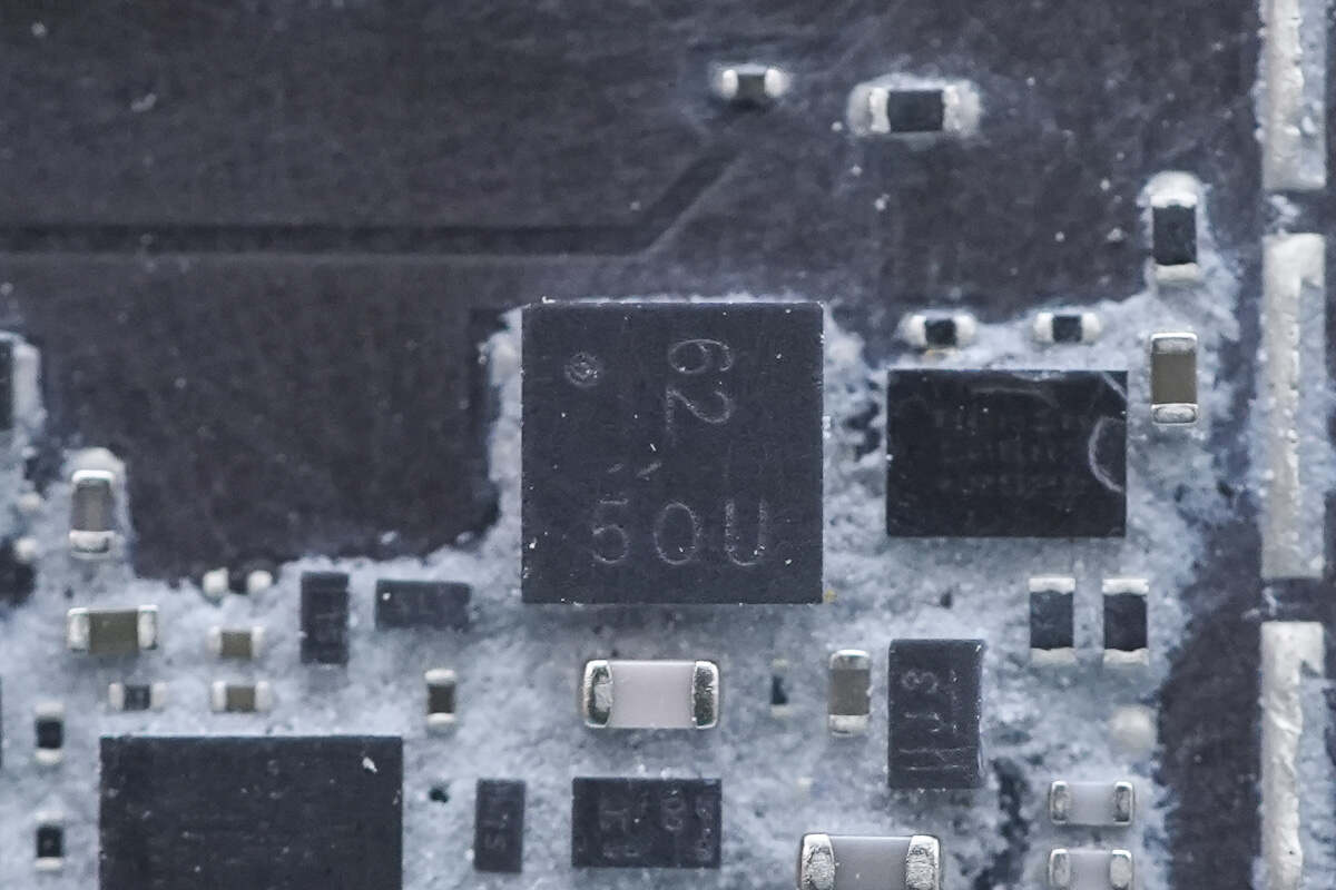
Close-up of the MOSFET marked with "62."
This chip has no markings and cannot be identified.
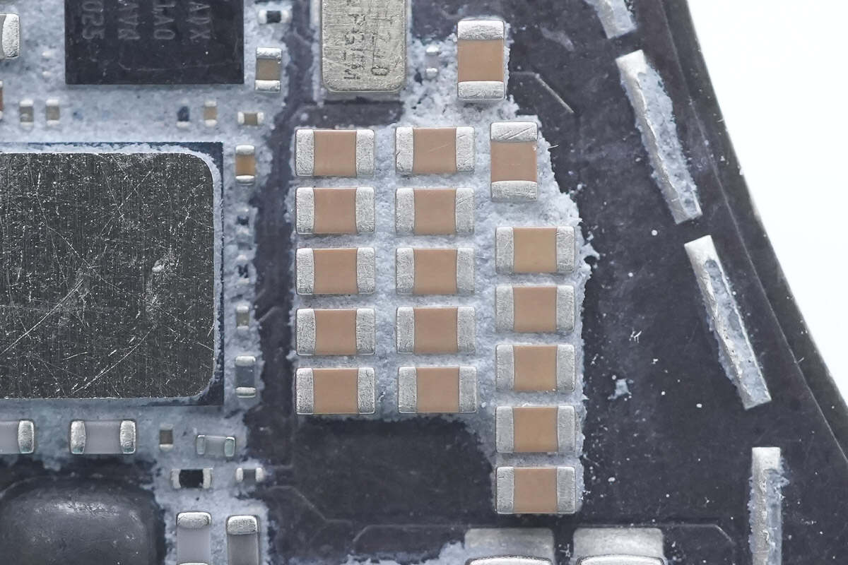
Close-up of the MLCC capacitors used for wireless charging filtering.
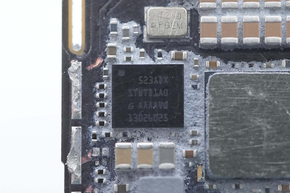
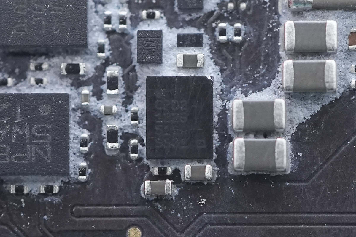
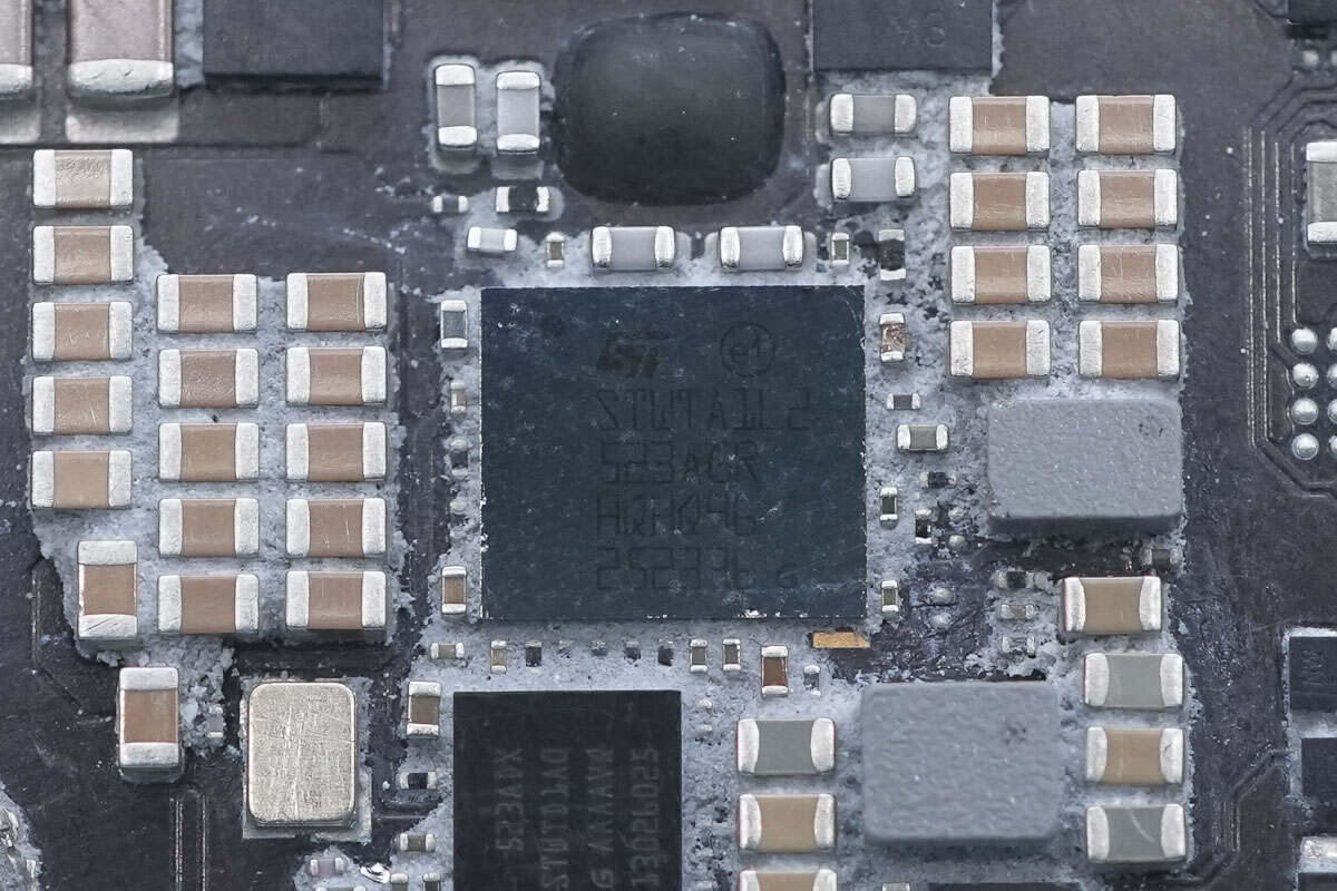
The wireless charging controller is from STMicroelectronics, marked with "STWTD1A0."
Close-up of the crystal oscillator.
Close-up of the memory chip.
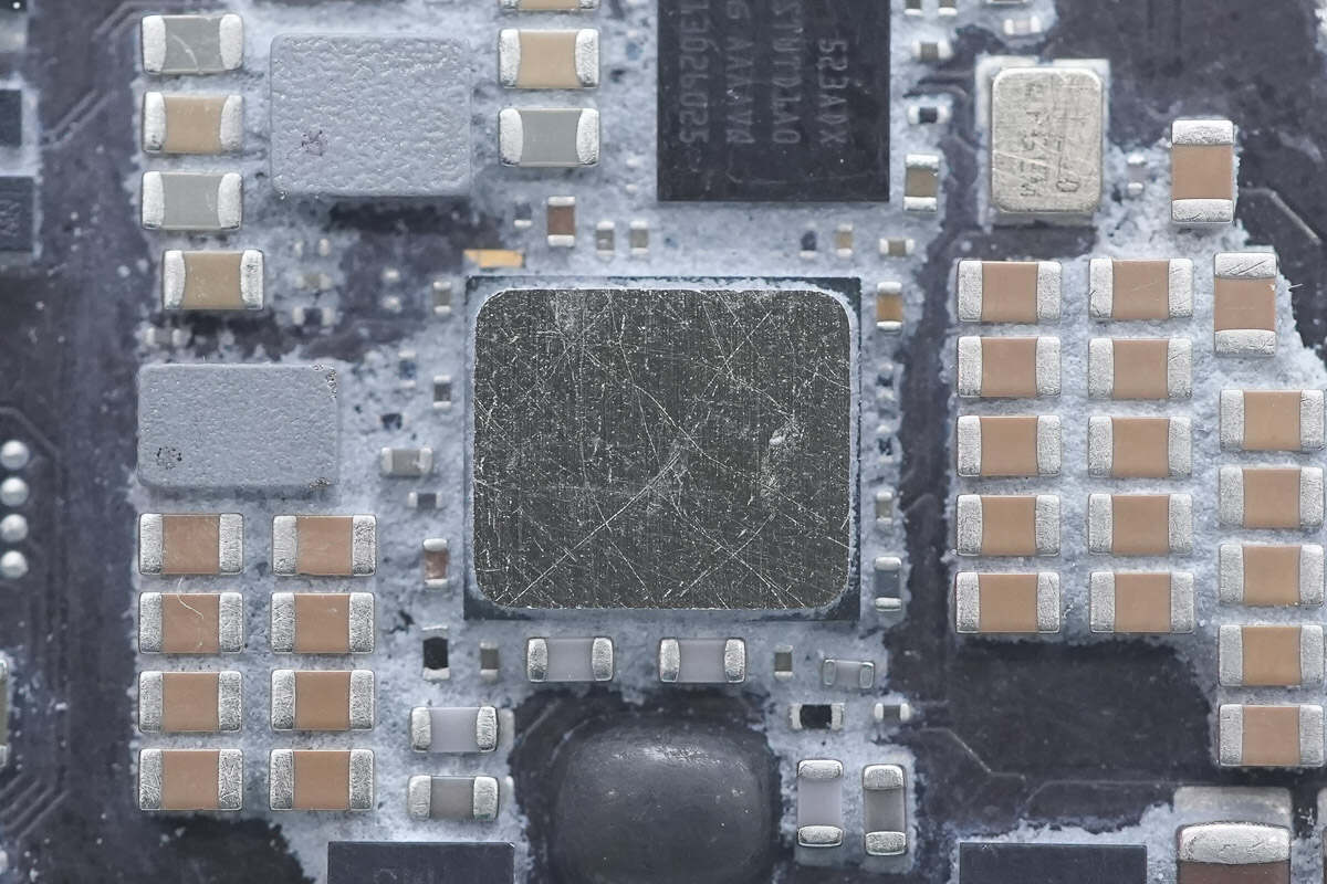
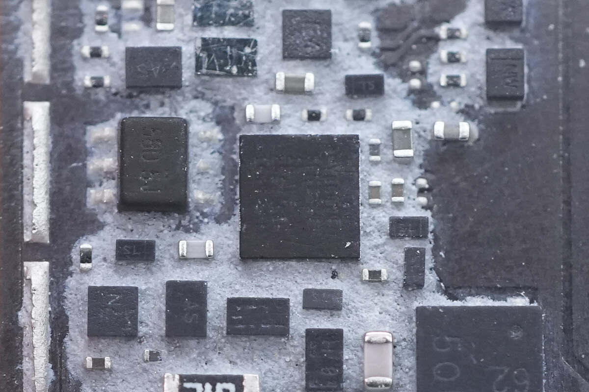
The wireless charging chip is attached to an aluminum plate by thermal adhesive to enhance heat dissipation.
The wireless charging chip is from STMicroelectronics, marked with "STWTA1L2."
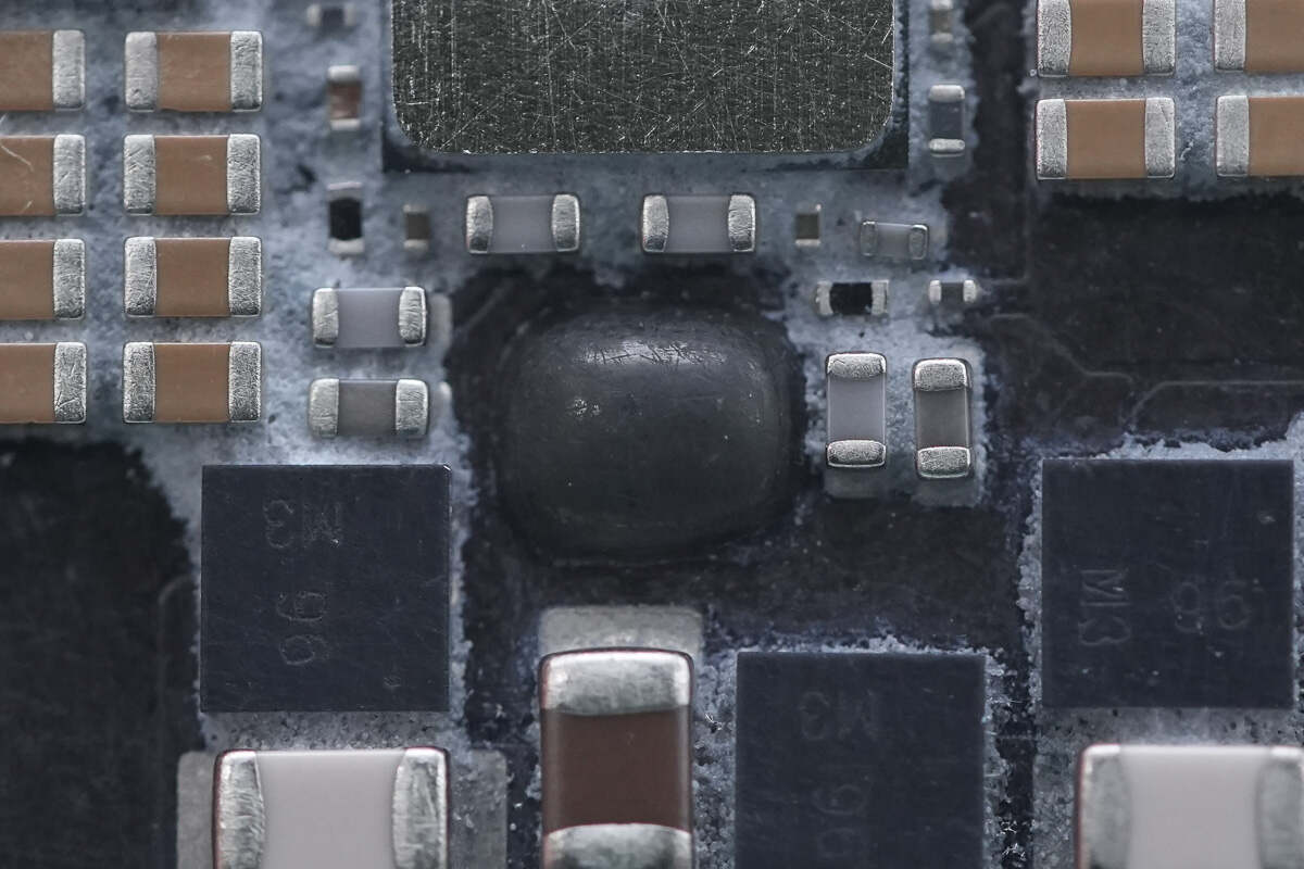
Close-up of the SMD inductor.
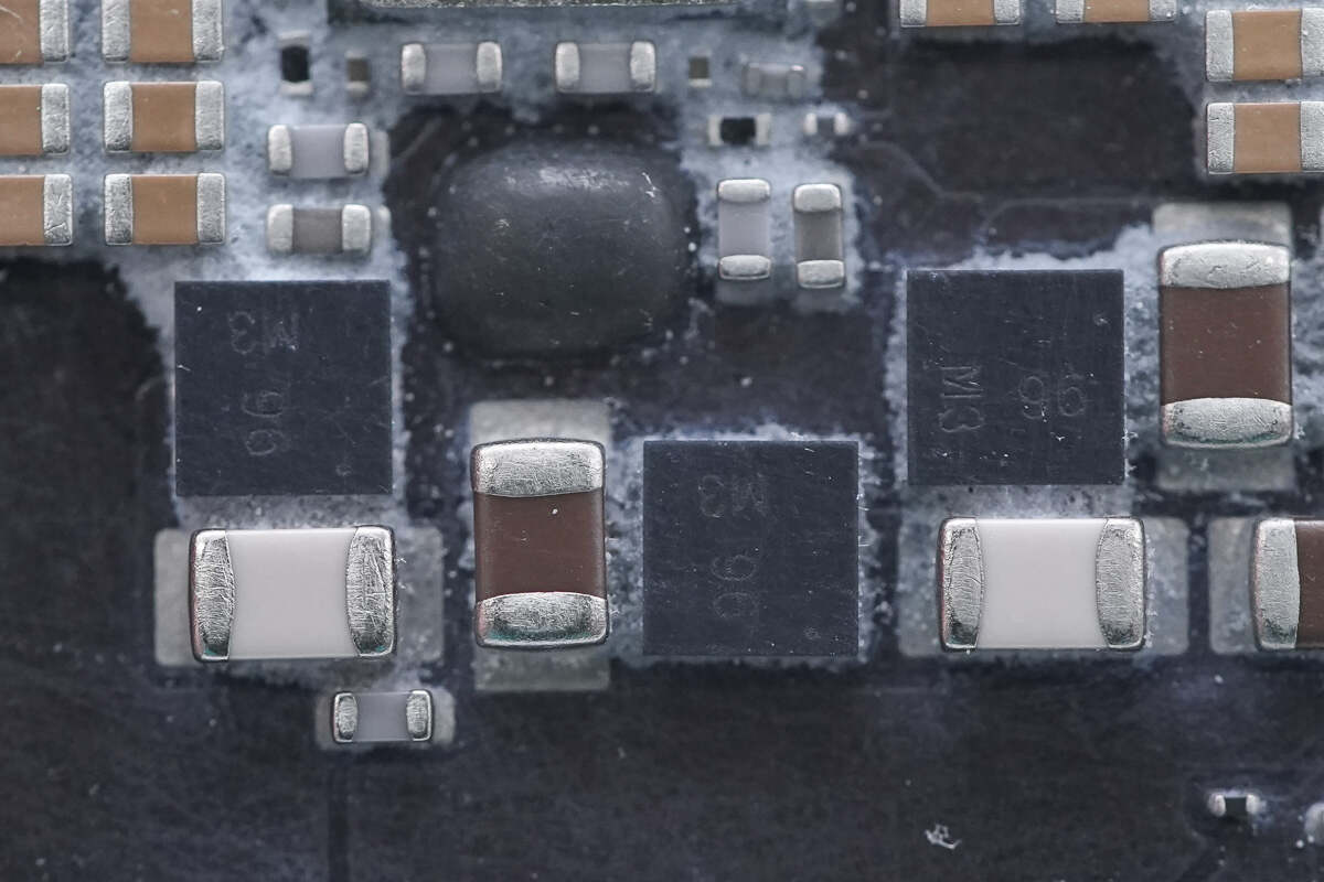
Close-up of the three MOSFETs marked with "96."
One area is covered with glue.
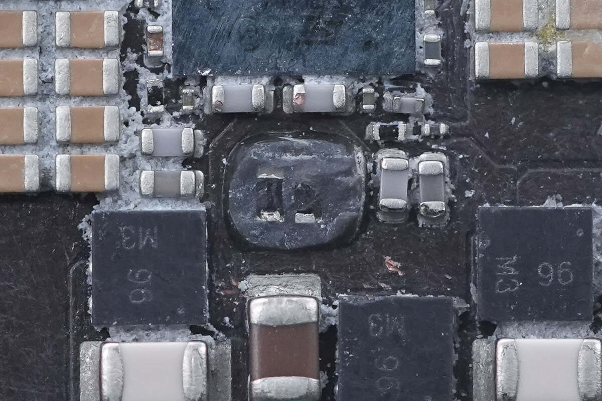
There are two resistors located beneath the glue.
The analog switch is from Texas Instruments, marked with "TU41," model TS5USBC41. It is a dual 2:1 switch with overvoltage protection, packaged in a DSBGA package.
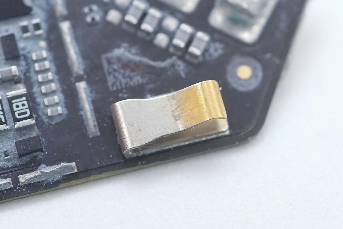
A metal spring contact connects the aluminum alloy cover plate to ground.
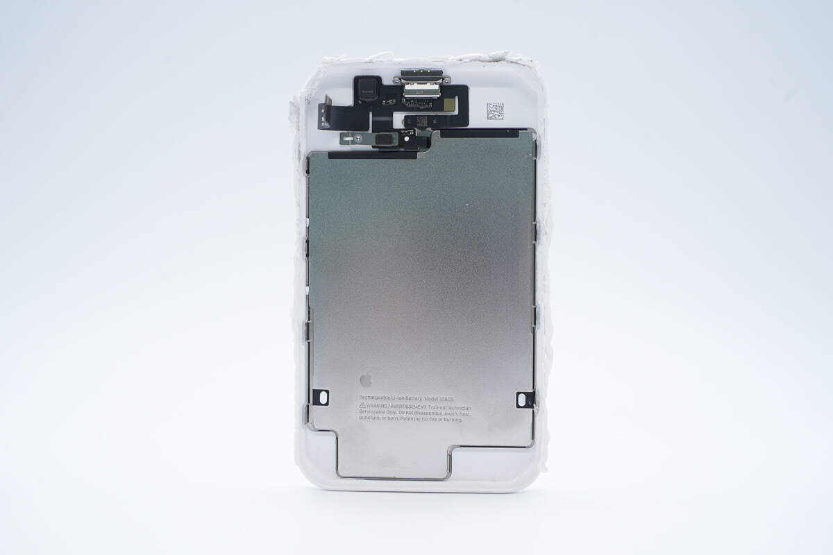
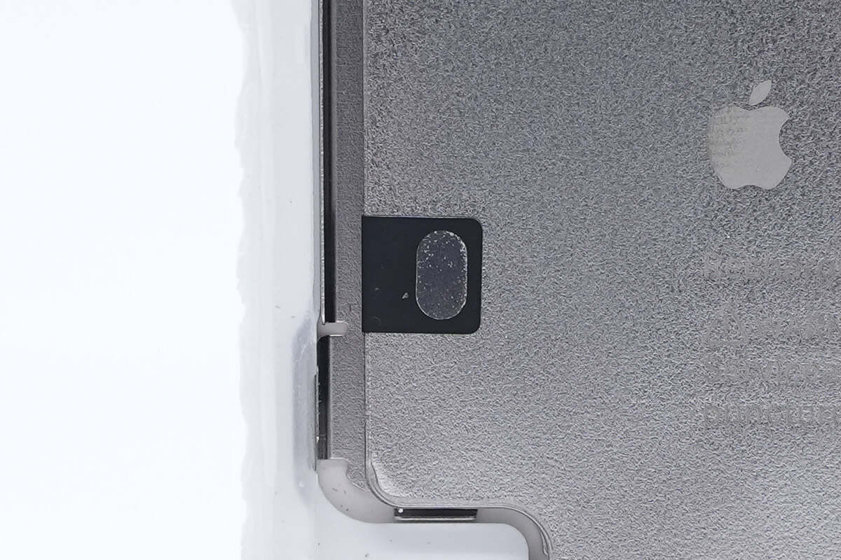
The steel-cased battery is attached inside the casing, with a flex cable connector located above it.
The flex cable is adhered to the casing.
The battery flex cable is secured with a screw clamp.
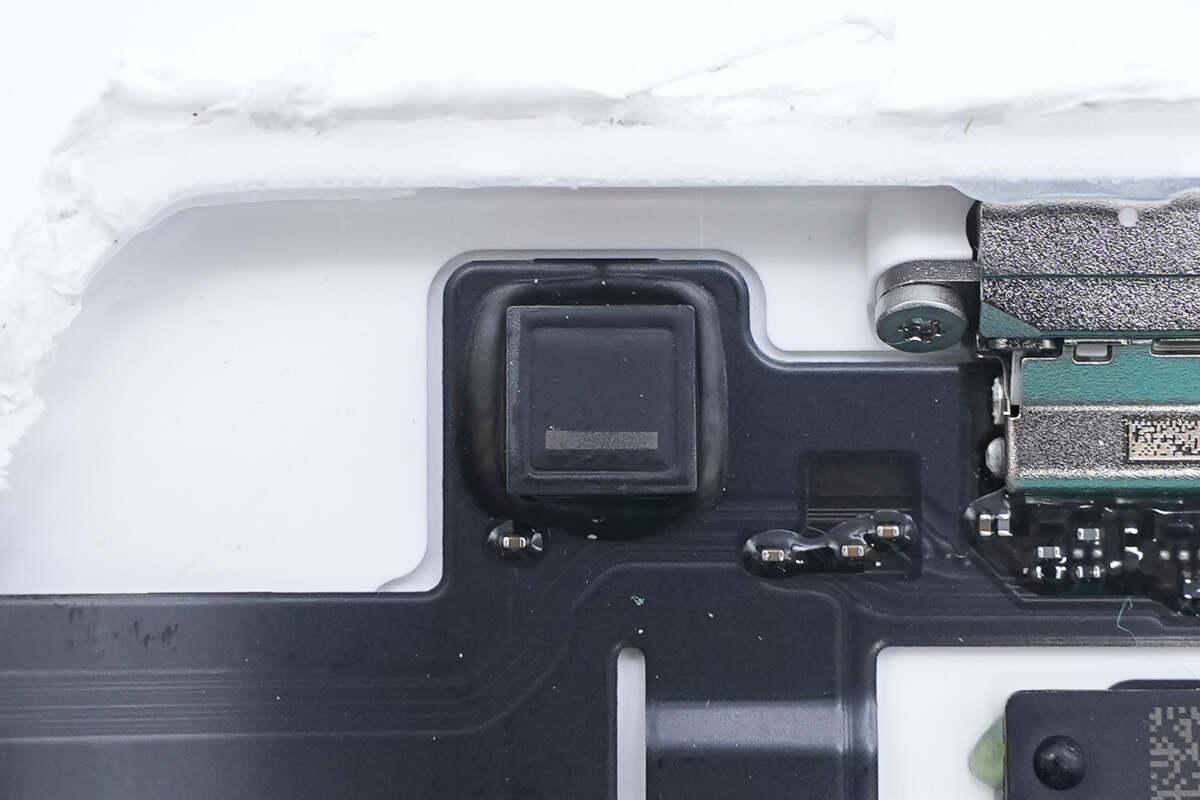
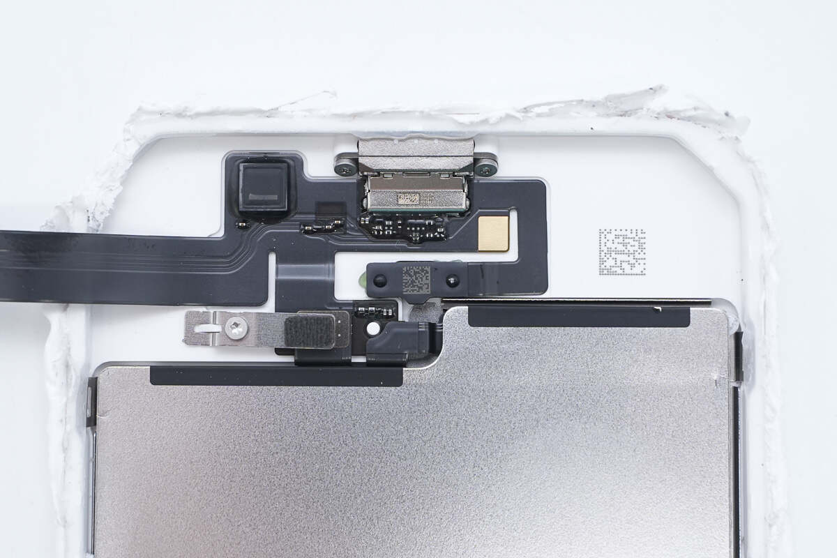
The flex cable includes a filter inductor.
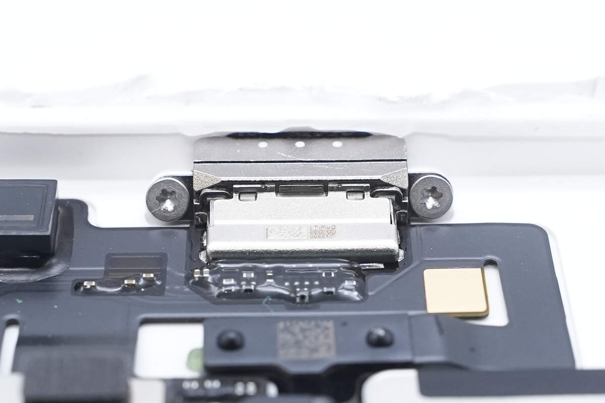
The USB-C socket is secured with screws.
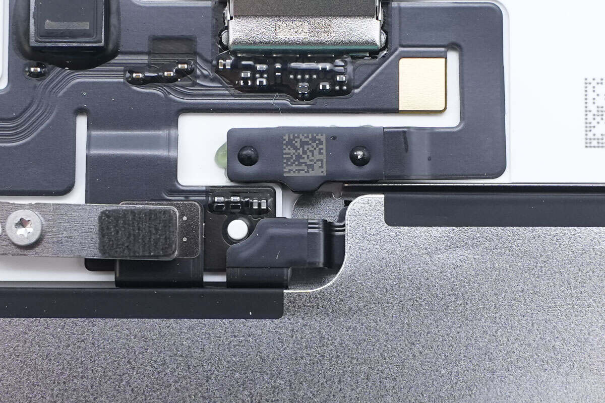
The indicator light is attached and secured with adhesive.
The battery is bonded using electrically conductive adhesive, with silver contacts on both sides.
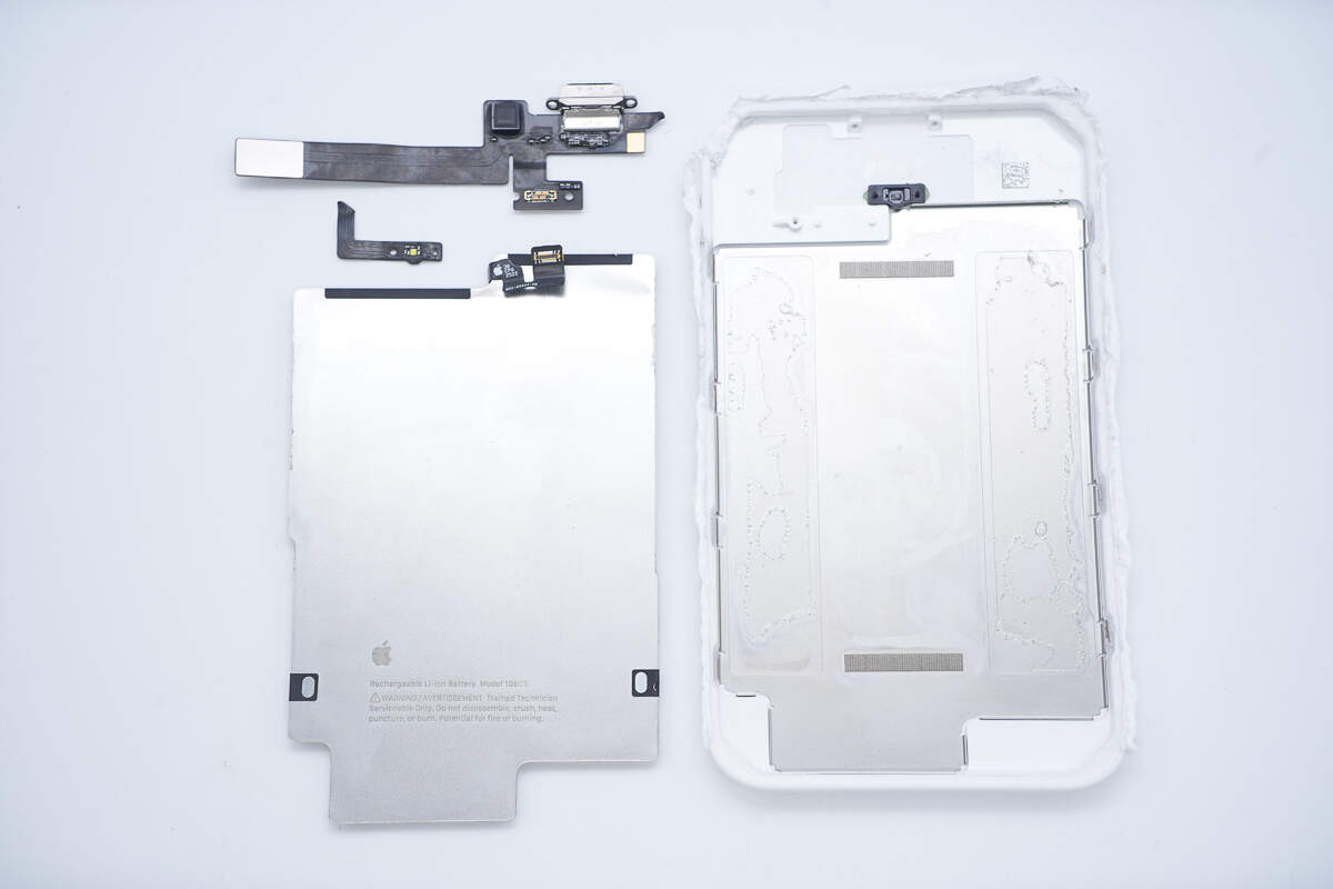
After removing the battery and the flex cable, a metal shell is revealed inside the casing to enhance structural strength.
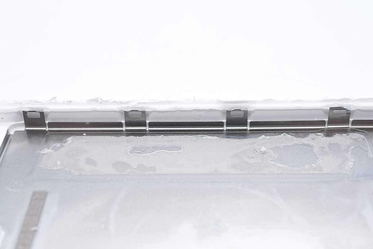
The edges of the metal shell have securing clips.
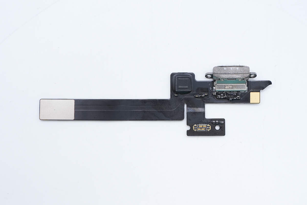
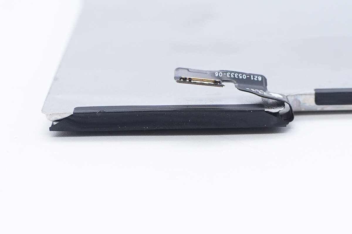
One side of the flex cable is equipped with a filter inductor, USB-C socket, and battery connector.

The other side features a connector for the wireless charging module.
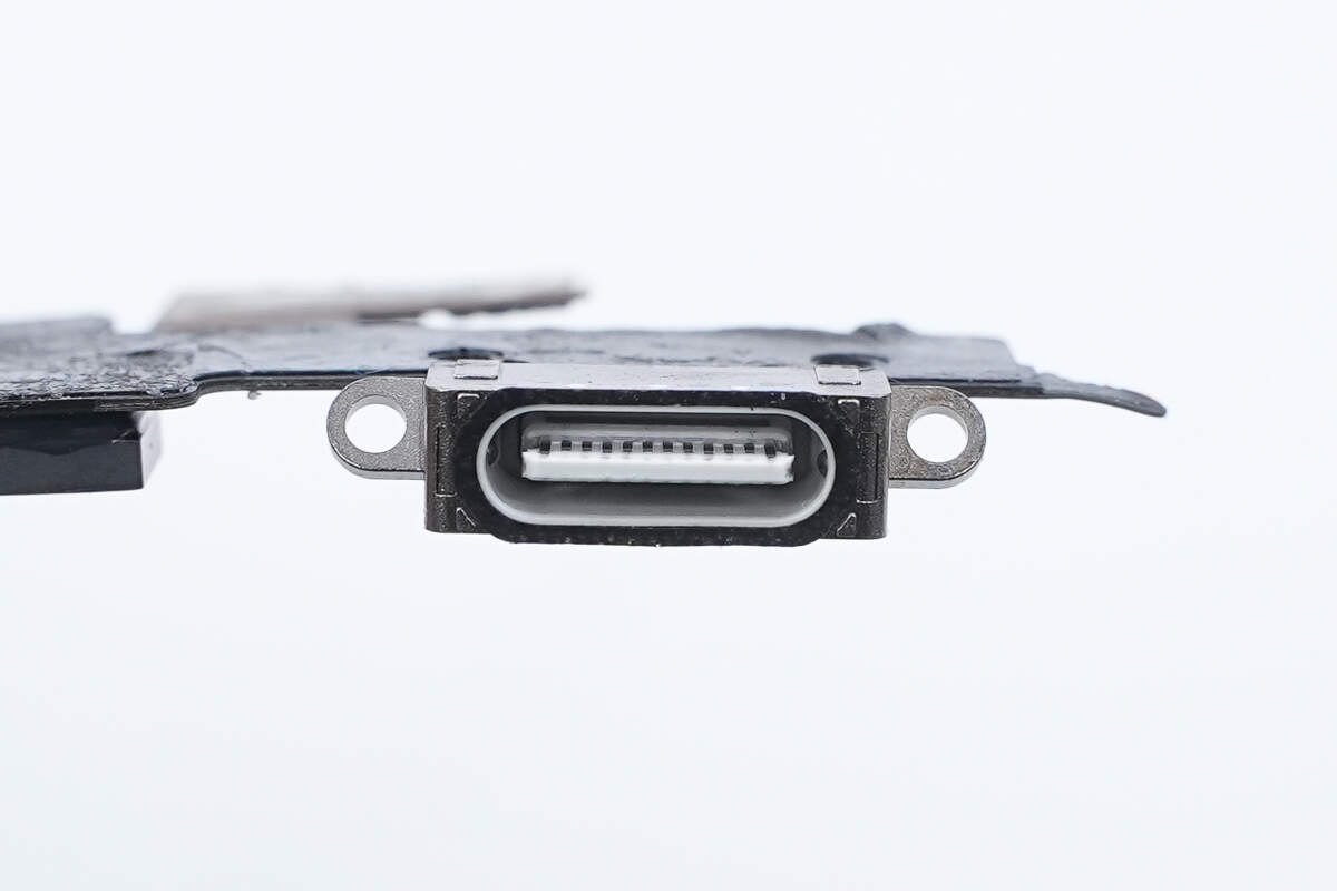
The USB-C socket has a white plastic sheet with a black rubber ring around the edge.
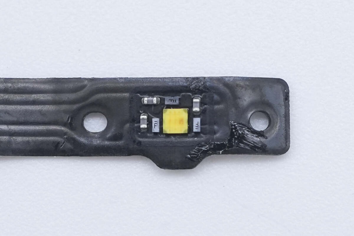
Close-up of the LED indicator light.
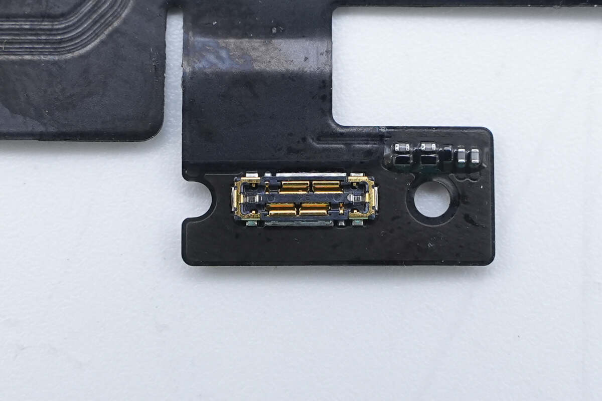
The battery connector features a widened design.
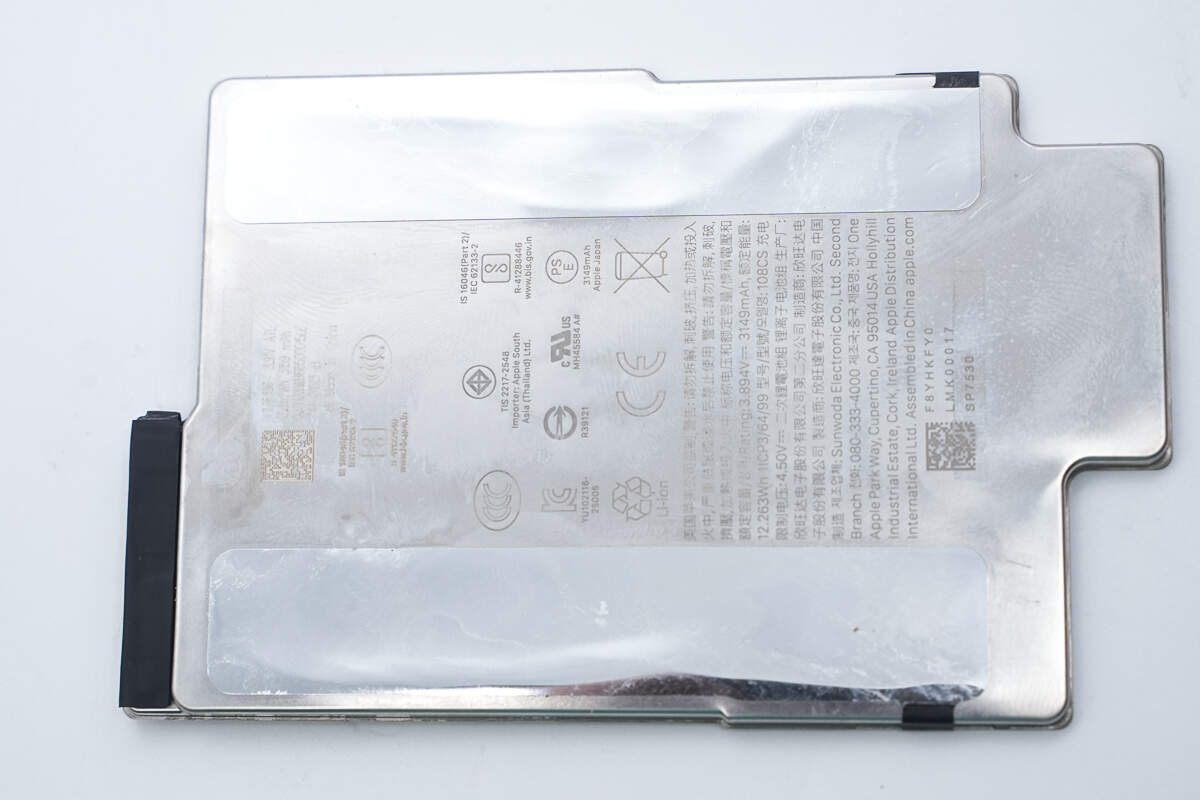
The battery is enclosed in a metal casing.
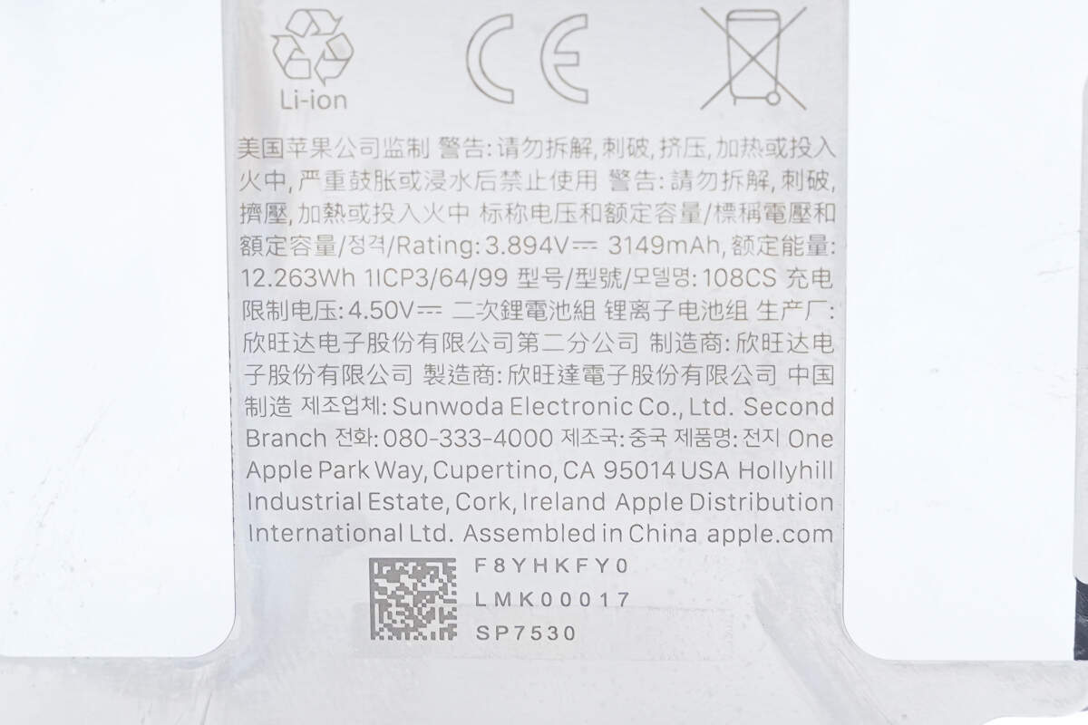
Nominal Voltage and Rated Capacity: 3.894V, 3149mAh
Rated Energy: 12.263Wh
Charge Limit Voltage: 4.5V
The battery is equipped with a protection PCB and a connecting flex cable.
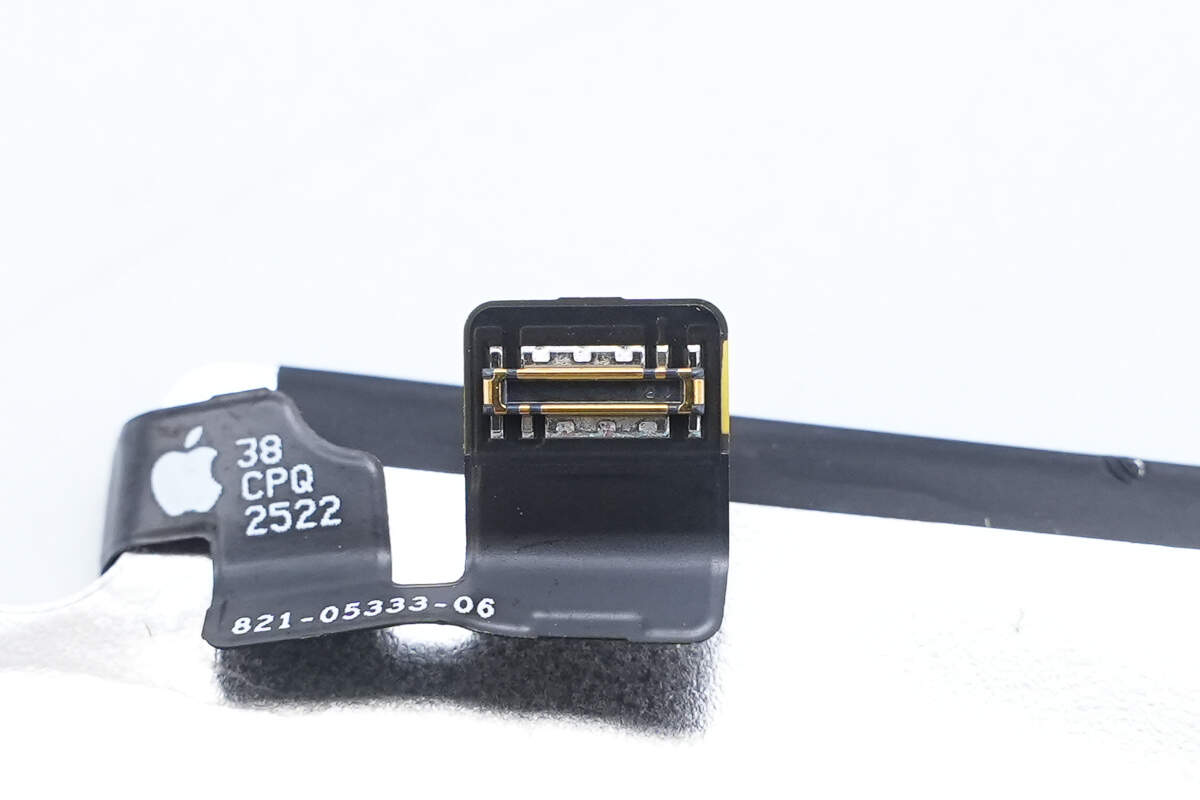
The connector features a widened design.
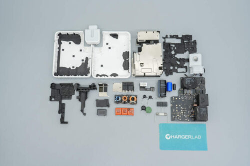
Well, those are all components of the Apple iPhone Air MagSafe Battery.
Summary of ChargerLAB
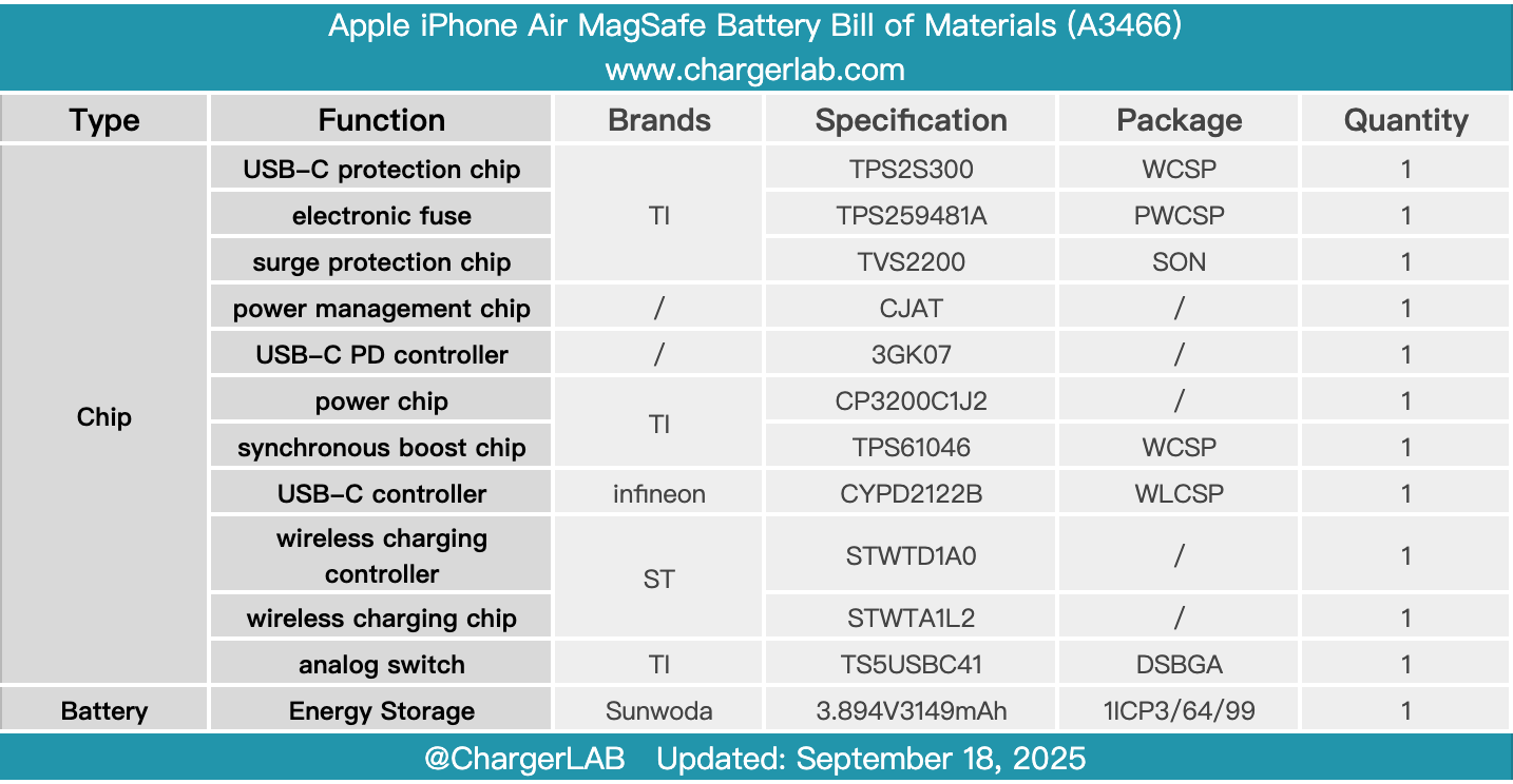
Here is the component list of the Apple iPhone Air MagSafe Battery for your convenience.
It is custom-designed for the iPhone Air. It features a built-in 3149mAh lithium battery—matching the phone’s internal capacity—and provides up to 65% additional battery life, extending video playback time from 27 hours to 40 hours. The battery includes a USB-C port that supports 9V/3A input and 5V/1.5A output.
After taking it apart, we found that the wireless charging module and battery use a separate design, connected via a flex cable. Both sides of the wireless charging module are covered with aluminum alloy plates and filled with thermal materials to enhance heat dissipation. The input side of the wireless charging module uses Texas Instruments protection and power chips, while the wireless charging controller and power stage chips come from STMicroelectronics.
The PCBA module is equipped with a shielding cover filled internally with thermal materials. Two heat-generating chips are attached to aluminum plates to shorten the heat transfer path and reduce temperature rise. The battery, sourced from Sunwoda, features a stainless steel casing. The internal structure of the MagSafe battery is compact and well-built, continuing Apple’s high-quality standards to ensure stable and reliable performance.
Related Articles:
1. Teardown of Apple 40W Dynamic Power Adapter with 60W Max (A3365)
2. Teardown of CalDigit TS5 Plus Thunderbolt 5 Dock
2. Teardown of EcoFlow RAPID Pro 140W 4‑Port GaN Charger (EF-WC-140-CN)